Duet3D Logo Duet3D
    • Tags
    • Documentation
    • Order
    • Register
    • Login
    1. Home
    2. The_Mechanic
    3. Posts
    • Profile
    • Following 0
    • Followers 0
    • Topics 2
    • Posts 13
    • Best 0
    • Controversial 0
    • Groups 0

    Posts made by The_Mechanic

    • RE: Change feed rate during Z homing

      @dc42
      Thank you very much!
      It works like you pointed out and how it wanted it to behave.

      But: one issue solved, another appeared...
      When I'm doing a G29 before the print I'm having the same settings for those probings, which take nearly 4 times longer.

      Is the solution to use
      M558 K0 P5 C"^io6.in" H2 F1000 T9000 A1 S0 before the G29?

      posted in Tuning and tweaking
      The_Mechanicundefined
      The_Mechanic
    • RE: Change feed rate during Z homing

      @dc42
      I nearly created a thread to ask for a solution like @deckingman and your post made me really happy!

      I applied this method to my routine but it doesn't work like intended.
      Where do I've the issue?

      I'm using a Klicky probe on my Voron Switchwire and I want to make a fast probe to get down to the surface, afterwards I want to do three slow and accurate probes.

      Here's my config and homez file

      Would be really grateful for some tips or hints!

      config.g

      ; Configuration file for Duet 3 Mini 5+ (firmware version 3)
      ; executed by the firmware on start-up
      ;
      ; General preferences
      M111 S0
      M575 P1 S1 B57600                                         ; enable support for PanelDue 
      G21
      G90                                                   	  ; send absolute coordinates...
      M83                                                   	  ; ...but relative extruder moves
      M550 P"Voron Switchwire"                                  ; set printer name
      M669 K2 X-1:0:-1 Z-1:0:1
      
      ; Network
      M552 S1                                               	  ; enable network
      M586 P0 S1                                            	  ; enable HTTP
      M586 P1 S0                                            	  ; disable FTP
      M586 P2 S0                                           	  ; disable Telnet
      
      ; Drives
      M569 P0.0 S0 D3	V0		
      M569 P0.1 S0 D3 V0                                 	  	  ; physical drive 0.1 goes forwards
      M569 P0.2 S1 D3 V0                                  	  ; physical drive 0.2 goes forwards
      M569 P20.0 S1 D3 V0                                       ; physical drive 0.3 goes forwards
      M584 X0.0 Y0.2 Z0.1 E20.0                    	          ; set drive mapping
      M350 X16 Y16 Z16 E16 I1                              	  ; configure microstepping with interpolation
      M92 X80.00 Y80.00 Z80.00 		               			  ; set steps per mm
      M92 E741.075
      M566 X600.00 Y600.00 Z1000.00 E1200.00              	  ; set maximum instantaneous speed changes (mm/min)
      M203 X30000.00 Y30000.00 Z30000.00 E10000.00              ; set maximum speeds (mm/min)
      M201 X5000.00 Y5000.00 Z5000.00 E30000.00                 ; set max accelerations (mm/s^2)
      M906 X1200 Y1700 Z1200 E650 I30                        	  ; set motor currents (mA) and motor idle factor in per cent
      M84 S30                                               	  ; Set idle timeout
      
      ; Axis Limits
      M208 X0 Y-8 Z0 S1                             			  ; set axis minima
      M208 X250 Y210 Z205 S0                         			  ; set axis maxima
      
      ; Axis compensation
      ;M556 S50 X0.10
      ;M579 X1.001717
      
      ; Endstops
      M574 X1 S4                                    			  ; configure sensorless endstop for low end on X
      M574 Z1 S2                                   			  ; configure sensorless endstop for high end on Z 
      M574 Y2 S1 P"io5.in"                                      ; configure active-high endstop for low end on Y via pin io5.in
      
      ; Z-Probe
      M558 K0 P5 C"^io6.in" H2 F4000 T9000 A1 S0.02   		  ; set Z probe type to unmodulated and the dive height + speeds
      M558 K1 P5 C"^io6.in" H2 F100 T9000 A3 S0.01   			  ; set Z probe for a second and more accurate G30
      G31 P5 X0 Y25                               			  ; set Z probe trigger value, offset and trigger height
      G31 Z6.20
      
      ;Mesh grid
      M557 X15:231 Y25:210 P7:7                        		  ; define mesh grid
      
      ; Heaters
      M308 S0 P"temp0" Y"thermistor" T100000 B3988              ; configure sensor 0 as thermistor on pin temp0
      M950 H0 C"out0" T0                                        ; create bed heater output on out0 and map it to sensor 0
      M307 H0 R0.274 K0.241:0.000 D12.01 E1.35 S1.00
      M140 H0                                                   ; map heated bed to heater 0
      M143 H0 S120                                              ; set temperature limit for heater 0 to 120C
      M308 S1 P"20.temp0" Y"thermistor" T100000 B4725 C7.06e-8  ; configure sensor 1 as thermistor on pin 121.temp0
      M950 H1 C"20.out0" T1                                     ; create nozzle heater output on 121.out0 and map it to sensor 1
      M307 H1 B0 S1.00                                          ; disable bang-bang mode for heater  and set PWM limit
      M143 H1 S295                                              ; set temperature limit for heater 1 to 295C 
      
      ; Fans
      M950 F0 C"20.out1" Q5000                                  ; create fan 0 on pin out3 and set its frequency
      M106 P0 C"Part cooling"                           	      ; set fan 0 name and value. Thermostatic control is turned on
      M950 F1 C"20.out2" Q5000                    	          ; create fan 1 on pin out2 and set its frequency, and tacho output on out2.tach
      M106 P1 S1 H1 T50                                         ; set fan 1 value. Thermostatic control is turned on
      
      ; Tools
      M563 P0 D0 H1 F0                              	    	  ; define tool 0
      G10 P0 X0 Y0 Z0                                      	  ; set tool 0 axis offsets
      G10 P0 R0 S0                                         	  ; set initial tool 0 active and standby temperatures to 0C
      
      ; Miscellaneous
      M950 S0 C"out6"						  	    			  ; assign GPIO port 0 to heater3 on expansion connector, servo mode
      M280 P0 S154
      T0                                                 	      ; select first tool
      M150 X3
      M98 P"/macros/neopixel/startup.g"
      
      ;; Global variables
      M98 P"/macros/startup/set_globals.g"
      
      ; After startup
      M98 P"/macros/startup.g"							 	  ;tone after config file was completely executed


      homez.g

      ; Z-Home
      M564 H0
      G91                									  	 ; relative mode
      G1 Z10 F2000     										 ; raise head 4mm to ensure it is above the Z probe trigger height
      M564 H1
      M98 P"/macros/zprobe/loadclicky.g"						 ; call macro to load the Klicky probe
      M400													 ; Wait for current moves to finish
      G90                									     ; back to absolute mode
      G1 H0 X125 F10000 										 ; put head over the x-axis centre of the bed, or wherever you want to probe
      G1 H0 Y90 F10000										 ; put head over the y-axis centre of the bed, or wherever you want to probe
      ;M558 P5 C"^io6.in" H2 F4000 T9000 A1 S0.02   			 ; set Z probe type to unmodulated and the dive height + speeds
      G30 K0               	 									 ; lower head, stop when probe triggered and set Z to trigger height
      ;G4 P500
      M400
      G1 Z5 F1000
      G30 K1
      ;M558 P5 C"^io6.in" H2 F100 T9000 A3 S0.01   			 ; set Z probe for a second and more accurate G30
      G91
      G1 Z15 F1000
      M98 P"/macros/zprobe/unloadclicky.g"					 ; call macro to unload the Klicky probe
      G90
      G1 X0 Y0 F10000
      M558 P5 C"^io6.in" H2 F500 T9000 A1 S0.01   			 ; set Z probe to standard back
      M564 S1
      
      posted in Tuning and tweaking
      The_Mechanicundefined
      The_Mechanic
    • RE: Non Duet Hardware with RRF ?

      @pixelpieper
      Are there any news on your project or is it possible to continue working on it (if you may share the files)?
      I really like your approach and want to use is for my Voron Switchwire.

      posted in Duet Hardware and wiring
      The_Mechanicundefined
      The_Mechanic
    • RE: Another BLTouch Topic

      I've found something interesting.
      @JoergS5 gave me a hint.

      My DueX2 is a version 0.8 and when I read the features section from the DueX2 and DueX5 I see this:

      Duex 2 v0.8 and older

      2 additional TMC2660 stepper motor drivers with stall notification.
      2 additional extruder heater outputs.
      2 servo outputs with 5V power and 5V signal levels, sharing control channels with the heaters. So you can use unused heater channels to drive servos.
      2 additional endstop inputs with indicator LEDs and 3.3V/5V voltage selection. These are also usable as outputs.
      6 additional PWM controlled fan outputs*, also usable for driving LEDs etc. The output voltage may be switched between 5V, 12V and VIN .
      4 uncommitted general purpose I/O pins.
      12V switching regulator, for generating a 12V supply for fans, LEDs etc. when the VIN power is higher than 12V.
      2 additional thermistor inputs.
      Support for 2 more thermocouple or PT100 daughter boards, supporting up to 4 more sensors.
      Optional 5V external power input for powering servos, fans etc.
      

      Duex 2 v0.8a and newer

      2 additional TMC2660 stepper motor drivers with stall notification.
      5 additional extruder heater outputs.
      5 servo outputs with 5V power and 5V signal levels, sharing control channels with the heaters. So you can use unused heater channels to drive servos.
      5 additional endstop inputs with indicator LEDs and 3.3V/5V voltage selection. These are also usable as outputs.
      6 additional PWM controlled fan outputs, also usable for driving LEDs etc. The output voltage may be switched between 5V, 12V and VIN .
      4 uncommitted general purpose I/O pins.
      12V switching regulator, for generating a 12V supply for fans, LEDs etc. when the VIN power is higher than 12V.
      5 additional thermistor inputs.
      Support for 2 more thermocouple or PT100 daughter boards, supporting up to 4 more sensors.
      Optional 5V external power input for powering servos, fans etc.
      

      Now the crazy part. I have a 0.8 and not a 0.8a but I can use the servo ports 1-3. This is really strange and does not apply to any logic.

      @dc42
      May you could tell me where I'm wrong or misunderstand something?

      posted in Duet Hardware and wiring
      The_Mechanicundefined
      The_Mechanic
    • RE: Another BLTouch Topic

      @JoergS5
      Your're right. Thats wirtten on the board but it's a DueX2.

      M122
      === Diagnostics ===
      RepRapFirmware for Duet 2 WiFi/Ethernet version 3.1.1 running on Duet WiFi 1.02 or later + DueX2
      Board ID: 08DDM-9FAM2-LW4S4-6JTD6-3SJ6L-1LVRY
      Used output buffers: 3 of 24 (23 max)

      I think thats because they share the same shematic.

      posted in Duet Hardware and wiring
      The_Mechanicundefined
      The_Mechanic
    • RE: Another BLTouch Topic

      @JoergS5
      Don't get me wrong. It's a DueX2. I've read through these two boards and the only differences are the three TMC2660 that are not soldered. Am I right?

      I'm using the expansion board only because of my three z-axis, the BLTouch and two fans, that's all. 😕

      posted in Duet Hardware and wiring
      The_Mechanicundefined
      The_Mechanic
    • RE: Another BLTouch Topic

      @JoergS5
      Thanks for that hint. This was a prolem I had in the past. But actually all ports do get 5V.
      There must be something else wrong.

      posted in Duet Hardware and wiring
      The_Mechanicundefined
      The_Mechanic
    • RE: Another BLTouch Topic

      @Phaedrux
      I've sent M280 P2 S120 (BLTouch self test) through the console.
      I don't change the P2 in my M280 command because the only change must be done in the config.g for the PWM port.

      M950 S2 C"duex.pwm4" (I've changed the '.pwm to .pwm2, 3, 4 etc.)

      It works on the other ports.

      The strange thing about these two PWM ports is that they have 5V (4.881 V measured with a multimeter).

      There must be something wrong with the PWM signal.

      posted in Duet Hardware and wiring
      The_Mechanicundefined
      The_Mechanic
    • RE: Another BLTouch Topic

      I've some news about my problem.
      As @Phaedrux told me I've changed the PWM port to the first one on the DueX2 and it works since then.
      Meanwhile I've updated to RRF 3. After I've set the config like the older one with RRF 2 it works again.

      Now I've thought why not testing it again, maybe it was a firmware problem?!

      Here are the line out of my config.g

      M950 S0 C"duex.pwm1" ; create servo pin 0 for BLTouch
      M950 S2 C"duex.pwm4" ; create servo pin 0 for BLTouch

      I've two BLTouch's for testing. The first one works since the workaround and also on RRF 3.
      After another test with PWM port 4 and 5 I come to the conclusion that it must be a hardware problem. PWM port 4 and 5 do not work.

      There is nothing in the config-override.g that could occupy the ports.

      Here's also a picture of my DueX2.
      IMG_20200613_200437.jpg

      Has someone a idea?

      The workaround from @Phaedrux does work and solves the problem for me so this topic can be marked as solved.

      posted in Duet Hardware and wiring
      The_Mechanicundefined
      The_Mechanic
    • RE: Another BLTouch Topic

      @Phaedrux

      That's really strange. I've tested (like you told me) the first PWM port (PWM3) and it works. It works also with the PWM4. What makes me curious is that it doesn't work with PWM7.

      If I don't change the config and only unplug the DueX2 and connect the BLTouch directly to the pin PWM7 on the connector it works (inverting the signal is necessary).

      Isn't it strange? 😕

      For now it solves my problem, but I wan't to understand it and also to help others with this problem.

      In first place I've to thank you very much Phaedrux! Great tip!

      posted in Duet Hardware and wiring
      The_Mechanicundefined
      The_Mechanic
    • RE: Another BLTouch Topic

      Changed the M574 parameters as you told me.

      deployprobe.g
      M280 P7 S10

      retractprobe.g
      M280 P7 S90

      It's very crazy because the BLTouch does his selftest routine in the beginning so the wiring seems to be correct. If I write the commands via the console with and without I1 it doesn't do anything. Also the selftest via M280 P7 S120 doesn't work.

      As I wrote in my first post. If I unplug the DueX2 and type the commands via the console it works.
      Also I've changed the jumper position to 5V AUX.

      I don't know what to do more. O_o

      posted in Duet Hardware and wiring
      The_Mechanicundefined
      The_Mechanic
    • Another BLTouch Topic

      Good day to you fellows!

      I thought I could get this to work on my own but now I'm at a point where I don't know how to solve this or what causes this problem.

      I can't deploy or retract the probe nor do a selftest via M280 P7S120.

      My Setup is a Duet WiFi 1.02 with a DueX2. I'm using the Firmware version 2.05.
      The BLTouch is working and does a self test on startup.

      This is my second printer with a BLTouch and I've tested the Sensor with the wires hooked up to my second printer. It works!

      If I detache the DueX2 and wire it directly to the H7 pin like in the description on betrue3d.dk and also Invert the signal it works perfect!

      If I connect the DueX2 again, wire all up like I should and don't invert the signal it doesn't work.

      deployprobe.g and retractprobe.g is in the sys folder.

      Here is my config.g:

      ; General preferences
      M111 S0 ; Debugging off
      G21 ; Work in millimetres
      G90 ; Send absolute coordinates...
      M83 ; ...but relative extruder moves
      M555 P1 ; Set firmware compatibility to look like RepRapFirmware

      ; Machine Informations
      M669 K1 ; Select CoreXY mode
      M208 X0 Y0 Z0 S1 ; Set axis minima
      M208 X400 Y225 Z250 S0 ; Set axis maxima

      ; Endstops
      M574 Z0 S2
      M574 E0 S0 ; Set active low endstops
      M574 X1 Y1 S1 ; Set active high endstops
      M558 P9 X0 Y0 Z1 H5 F600 R0.05 A2 B0 T14000 ; Set Z Probe to type Switch or Digital output where Z probe connector is used. Used for z only.

      ;Offset for E3D Nozzle
      G31 P500 X0 Y100 Z0.0 ; Set Z probe trigger value, offset and trigger height

      ; Drives
      M569 P0 S1 ; Drive 0 goes forwards
      M569 P1 S1 ; Drive 1 goes forwards
      M569 P2 S1 ; Drive 2 goes forwards
      M569 P3 S0 ; Drive 3 goes forwards
      M569 P5 S1 ; Drive 5 goes forwards
      M569 P6 S1 ; Drive 6 goes forwards

      ;3-Z config
      M584 Z2:5:6 ; Driver 2,5,6 for the three z-axis
      M671 X-55:455:200 Y5:5:288 S10.0 ; defines leveling screw locations

      M350 X16 Y16 Z16 E16 I1 ; Configure microstepping with interpolation
      M92 X80 Y80 Z1600 ; Set steps per mm
      ;M92 E2700 ; Nimble
      ;M92 E418.35 ; Belted Extruder
      ;M92 E418.5 ; E3D Titan Aero
      M92 E418 ; Bondtech BMG
      M566 X500 Y500 Z200 E1200 ; Set maximum instantaneous speed changes (mm/min)
      M203 X40000 Y40000 Z600 E12000 ; Set maximum speeds (mm/min)
      M201 X3000 Y3000 Z200 E1500 ; Set accelerations (mm/s^2)
      M906 X750 Y750 Z700 E700 I20 ; Set motor currents (mA) and motor idle factor in per cent
      M84 S30 ; Set idle timeout

      ; Heaters
      M301 H0 S1.00 P10 I0.1 D200 T0.4 W180 B30 ; Use PID on bed heater (may require further tuning)
      M305 P0 T100000 B3988 C0 R4700 ; Set thermistor + ADC parameters for heater 0
      M143 H0 S120 ; Set temperature limit for heater 0 to 120C
      M305 P1 T100000 B4725 C7.06e-8 ; Set thermistor + ADC parameters for heater 1
      M143 H1 S310 ; Set temperature limit for heater 1 to 310C

      ; Tools
      M563 P0 D0 H1 F3 ; Define tool 0
      G10 P0 X0 Y0 Z0 ; Set tool 0 axis offsets
      G10 P0 R0 S0 ; Set initial tool 0 active and standby temperatures to 0C

      ; Disable heaters for free PWM channels
      M307 H7 A-1 C-1 D-1 ; Disable heater 7 for BLTouch PWM pin

      ; Network
      M550 Pbig_one ; Set machine name
      M552 S1 ; Enable network
      M586 P0 S1 ; Enable HTTP
      M586 P1 S0 ; Disable FTP
      M586 P2 S0 ; Disable Telnet

      ; Fans

      M106 P0 S255 I0 F400 H1 T45 ; Set fan 1 value, PWM signal inversion and frequency. Thermostatic control is turned on
      ;M106 P3 S0 I0 F400 ; Set fan 4 value, PWM signal inversion and frequency. Thermostatic control is turned on

      ; Custom settings are not configured

      M501

      Also my config-override.g file:

      ; This is a system-generated file - do not edit
      ; Heater model parameters
      M307 H0 A90.0 C700.0 D10.0 S1.00 V0.0 B1
      M301 H0 P10.0 I0.100 D200.0
      M307 H1 A438.1 C214.5 D6.0 S1.00 V24.1 B0

      Here you can see pictures of my wiring:

      IMG_2549.JPG

      IMG_2548.JPG

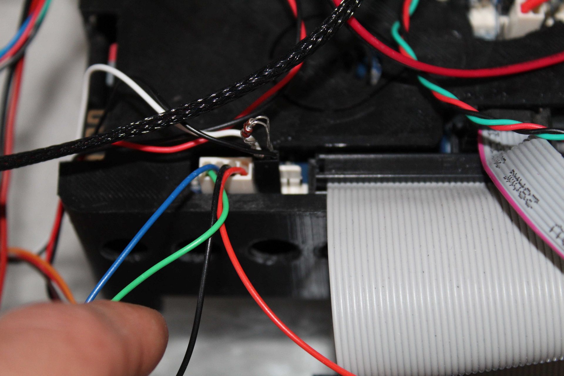
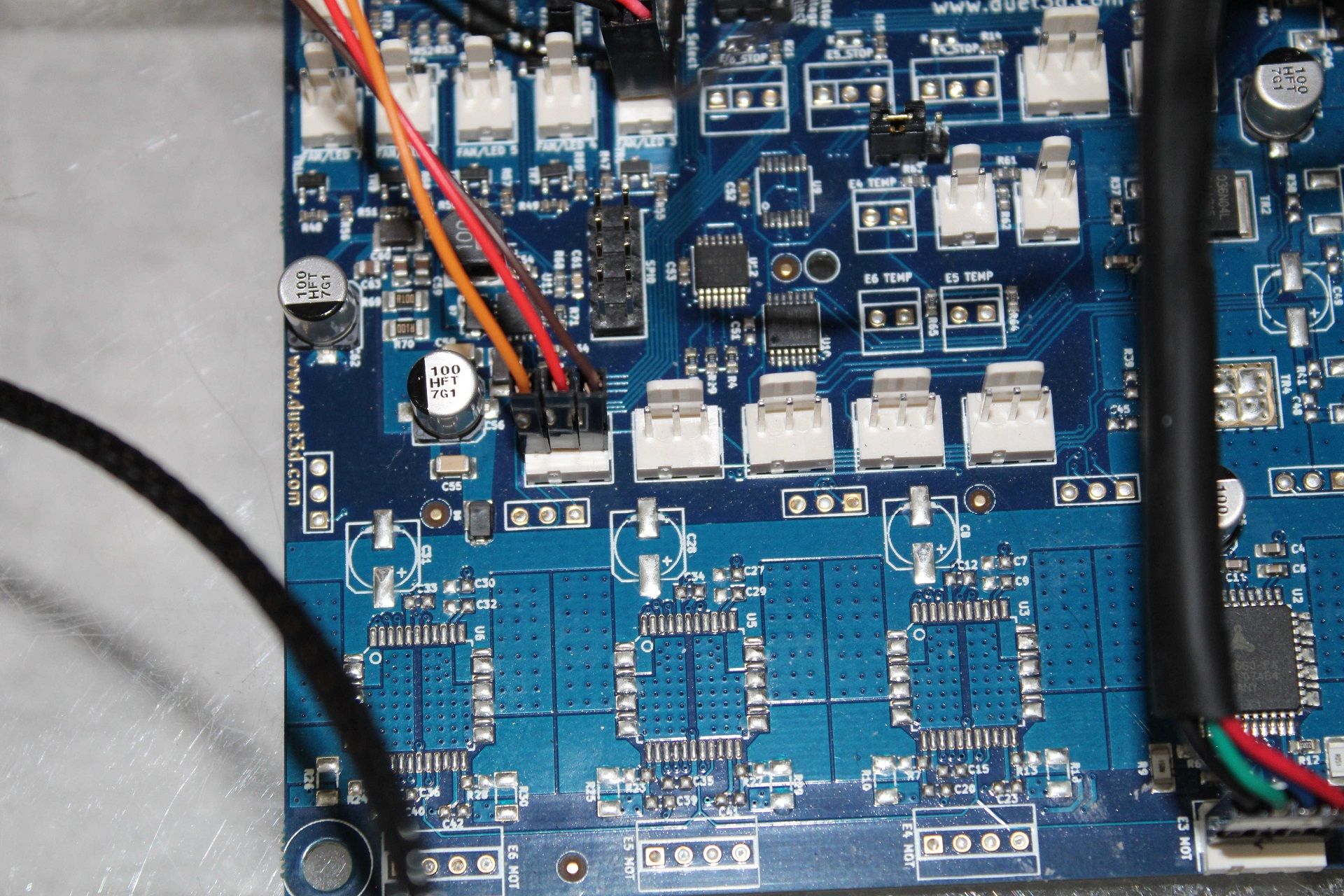
      I Don't get it. What am I doing wrong?
      I've read through all the post and reviewed my setup more then five times also I've done some test with a different board and without the DueX2.

      It would be very nice if someone could help me and point out what I'm doing wrong or not correct.

      Kind regards
      Andreas

      posted in Duet Hardware and wiring
      The_Mechanicundefined
      The_Mechanic
    • LED-Strip / illumination controlled with extruder heater 2

      Hello and many greetings dear community!

      I've learnd so many things with the help of this forum, so I'll give something, that I've learned, back.
      I'm using a LED illumination for my printer housing and wanted to controll it over the web interface.

      I dind't found the right thread in this forum but continued searching and found a answer, from David Crocker, in a google group.

      I had a problem. I damaged my duet wifi and now I can only use two controllable fan outputs, instead of three, so I had to find a nother way.
      Why not using the E1 heater and controll it with PWM values?

      Here is my solution:

      I've created some macros with the following coding lines:
      M307 H2 A-1 C-1 D-1 ; disable the heater functionality
      M42 P2 S0 ; controll P2 with PWM values (S###)

      (thanks to David)

      I think the M307 code could be added to the config.g, but it didn't worked for me. Please let me know, if I've made a mistake and it works.

      Happy printing! 🙂

      My greetings
      Andreas

      posted in Example setups and prints
      The_Mechanicundefined
      The_Mechanic