@dc42 Thank you so much for rescuing me from my own stupidity ")
now working
Posts made by usas12
-
RE: PT100 Duet 2 daughter board issuesposted in Duet Hardware and wiring
-
RE: PT100 Duet 2 daughter board issuesposted in Duet Hardware and wiring

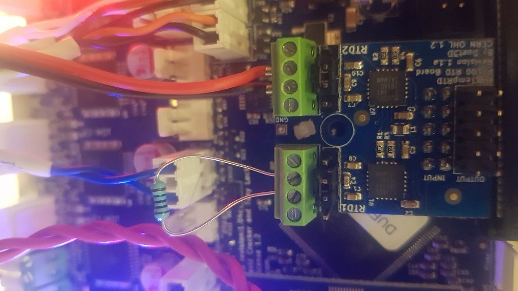
No on the resistor i get 2000 degrees
-
PT100 Duet 2 daughter board issuesposted in Duet Hardware and wiring
Sorry guys, another PT100 topic post
I have been through the search engine and havent been able to discover my issue.
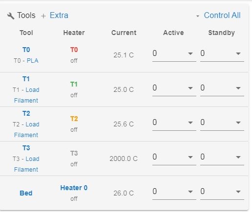
I'm getting 2000 degrees on Tool 4 where the PT100 is. Its a new daughter board and new PT100 dyze hotend. Im running RRF 3.2 on a E3d Toolchanger.I've tried the resister still 2000
I've tried powering via USB still 2000
I've tried the right and left connector on the board no change; Heaters
M308 S0 P"bedtemp" Y"thermistor" T100000 B4138 C0 ; Set thermistor
M950 H0 C"bedheat" T0 ; Bed heater
M140 H0
M143 H0 S225 ; Set temperature limit for heater 0 to 225C
M308 S1 P"e0temp" Y"thermistor" A"T0" T100000 B4725 C7.06e-8 ; Set thermistor
M950 H1 C"e0heat" T1 ; Extruder 0 heater
M143 H1 S300 ; Set temperature limit for heater 1 to 300C
M308 S2 P"e1temp" Y"thermistor" A"T1" T100000 B4725 C7.06e-8 ; Set thermistor
M950 H2 C"e1heat" T2 ; Extruder 0 heater
M143 H2 S300 ; Set temperature limit for heater 2 to 300C
M308 S3 P"e2temp" Y"thermistor" A"T2" T100000 B4725 C7.06e-8 ; Set thermistor
M950 H3 C"duex.e2heat" T3 ; Extruder 0 heater
M143 H3 S300 ; Set temperature limit for heater 3 to 300C
M308 S4 P"spi.cs1" Y"rtd-max31865" A"T3" ; create sensor number 1 as a PT100 sensor in the first position on the Duet 2 daughter board connector
M950 H4 C"duex.e3heat" T4 ; Extruder 0 heater
M307 H1 B0 S0.50
M143 H4 S480 ; Set temperature limit for heater 4 to 480C
-
RE: Error: bad command T3 t3pre.gposted in General Discussion
tpre3.g
; called before tool 3 is selected;Unlock Coupler
M98 P"/macros/Coupler - Unlock";Move to location
G1 X155 Y100 F25000;Move in
G1 X155 Y125 F25000;Collect
G1 X155 Y133.3 F2500;Close Coupler
M98 P"/macros/Coupler - Lock";WARNING! WARNING! WARNING! WARNING! WARNING! WARNING! WARNING! WARNING! WARNING! WARNING! WARNING! WARNING!
;if you are using non-standard length hotends ensure the bed is lowered enough BEFORE undocking the tool!
G91
G1 Z60 F1000
G90;Move Out
-
RE: Error: bad command T3 t3pre.gposted in General Discussion
; Configuration file for Duet WiFi / Ethernet running RRF3.01 on E3D Tool Changer
; executed by the firmware on start-up
; General preferencesM575 P1 S1 B57600
M111 S0 ; Debugging off
G21 ; Work in millimetres
G90 ; Send absolute coordinates...
M83 ; ...but relative extruder moves
M555 P2 ; Set firmware compatibility to look like Marlin
; Network
M550 P"ToolChanger" ; Set machine name
M552 S1 ; Enable Networking
M586 P0 S1 ; Enable HTTP
M586 P1 S0 ; Disable FTP
M586 P2 S0 ; Disable Telnet
M667 S1 ; Select CoreXY mode
; Drive direction
M569 P0 S0 ; Drive 0 X
M569 P1 S0 ; Drive 1 Y
M569 P2 S1 ; Drive 2 Z
M569 P3 S0 ; Drive 3 E0
M569 P4 S0 ; Drive 4 E1
M569 P5 S1 ; Drive 5 E2
M569 P6 S1 ; Drive 6 E3
M569 P7 S0 ; Drive 7 COUPLER
M569 P8 S0 ; Drive 8 UNUSED
M569 P9 S0 ; Drive 9 UNUSED
M584 X0 Y1 Z2 C7 E3:4:5:6 ; Apply custom drive mapping
;M208 X-35:328.5 Y-49:243 Z0:300 C0:500 ; Set axis maxima & minima
M208 X-185:178.5 Y-149:145 Z0:300 C0:500 ; Set axis maxima & minima
M92 X100 Y100 Z1600 C200 E834:834:834:834 ; Set steps per mm assuming x16 microstepping
M350 E16:16:16:16 I1 ; Configure microstepping with interpolation
M350 C16 I1
M350 X16 Y16 Z16 I1 ; Configure microstepping with interpolation
M566 X400 Y400 Z8 C2 E200:200:200:200 ; Set maximum instantaneous speed changes (mm/min)
M203 X35000 Y35000 Z1200 C10000 E5000:5000:5000:5000 ; Set maximum speeds (mm/min)
M201 X6000 Y6000 Z400 C500 E2500:2500:2500:2500 ; Set accelerations (mm/s^2)
M906 X2000 Y2000 Z1330 C500 E1600:1600:1600:1600 I30 ; Set motor currents (mA) and motor idle factor in percent
M913 C50
M84 S120 ; Set idle timeout; Endstops
M574 X1 Y1 S3 ; Set X / Y endstop stall detection
M574 Z0 ; No Z endstop
M574 C1 S3 ; Stall detect coupler at low end of its range
; Z probe
M558 P8 C"zstop" H3 F360 I0 T20000 ; Set Z probe type to switch, the axes for which it is used and the dive height + speeds
G31 P200 X0 Y0 Z0 ; Set Z probe trigger value, offset and trigger height
;M557 X10:290 Y20:180 S40 ; Define mesh grid
M557 X-140:140 Y-80:80 S40 ; Define mesh grid
;Stall Detection
M915 C S6 F0 H200 R4700 ; Coupler
;Stall Detection
M915 X Y S3 F0 H400 R4700 ; X / Y Axes
; Heaters
M308 S0 P"bedtemp" Y"thermistor" T100000 B4138 C0 ; Set thermistor
M950 H0 C"bedheat" T0 ; Bed heater
M140 H0
M143 H0 S225 ; Set temperature limit for heater 0 to 225C
M308 S1 P"e0temp" Y"thermistor" A"T0" T100000 B4725 C7.06e-8 ; Set thermistor
M950 H1 C"e0heat" T1 ; Extruder 0 heater
M143 H1 S300 ; Set temperature limit for heater 1 to 300C
M308 S2 P"e1temp" Y"thermistor" A"T1" T100000 B4725 C7.06e-8 ; Set thermistor
M950 H2 C"e1heat" T2 ; Extruder 0 heater
M143 H2 S300 ; Set temperature limit for heater 2 to 300C
M308 S3 P"e2temp" Y"thermistor" A"T2" T100000 B4725 C7.06e-8 ; Set thermistor
M950 H3 C"duex.e2heat" T3 ; Extruder 0 heater
M143 H3 S300 ; Set temperature limit for heater 3 to 300C
M308 S4 P"e3temp" Y"thermistor" A"T3" T100000 B4725 C7.06e-8 ; Set thermistor
M950 H4 C"duex.e3heat" T4 ; Extruder 0 heater
M143 H4 S300 ; Set temperature limit for heater 4 to 300C
; Tools
M563 P0 S"T0" D0 H1 F2 ; Define tool 0
G10 P0 X0 Y0 Z0 ; Reset tool 0 axis offsets
G10 P0 R0 S0 ; Reset initial tool 0 active and standby temperatures to 0C
M563 P1 S"T1" D1 H2 F4 ; Define tool 1
G10 P1 X0 Y0 Z0 ; Reset tool 1 axis offsets
G10 P1 R0 S0 ; Reset initial tool 1 active and standby temperatures to 0C
M563 P2 S"T2" D2 H3 F6 ; Define tool 2
G10 P2 X0 Y0 Z0 ; Reset tool 2 axis offsets
G10 P2 R0 S0 ; Reset initial tool 2 active and standby temperatures to 0C
M563 P3 S"T3" D3 H4 F8 ; Define tool 3
G10 P3 X0 Y0 Z0 ; Reset tool 3 axis offsets
G10 P3 R0 S0 ; Reset initial tool 3 active and standby temperatures to 0C
; Fans
; Fan0 output is not used
M950 F1 C"fan1"
M950 F2 C"fan2"
M950 F3 C"duex.fan3"
M950 F4 C"duex.fan4"
M950 F5 C"duex.fan5"
M950 F6 C"duex.fan6"
M950 F7 C"duex.fan7"
M950 F8 C"duex.fan8"
M106 P1 S255 H1 T70 ; T0 HE
M106 P2 S0 ; T0 PCF
M106 P3 S255 H2 T70 ; T1 HE
M106 P4 S0 ; T1 PCF
M106 P5 S255 H3 T70 ; T2 HE
M106 P6 S0 ; T2 PCF
M106 P7 S255 H4 T70 ; T3 HE
M106 P8 S0 ; T3 PCF
M593 F50 ; cancel ringing at 50Hz (https://forum.e3d-online.com/threads/accelerometer-and-resonance-measurements-of-the-motion-system.3445/)
M376 H15 ; bed compensation taper
;tool offsets
G10 P0 X-9 Y39 Z-4.9 ; T0
G10 P1 X-9 Y39 Z-4.9 ; T1
G10 P2 X-9 Y39 Z-13.24 ; T2
G10 P3 X-9 Y39 Z-5 ; T3
; Bowden tubes are ~700mm long so PA almost certainly needs to be increased
M572 D0 S0.2 ; pressure advance T0
M572 D1 S0.2 ; pressure advance T1
M572 D2 S0.2 ; pressure advance T2
M572 D3 S0.2 ; pressure advance T3 -
Error: bad command T3 t3pre.gposted in General Discussion
Can anyone tell me why I'm getting this error. I have a toolchanger and the other 3 docks run fine and are configured the same way. For some reason the firmware has started to take a disliking to T3
Thanks
-
Heated bed not registering RR 3.2posted in Tuning and tweaking
Hi guys,
Next problem. My heated bed does not seem to be registering, and is not displaying in the tool menu on the web interface. I'm running RR 3.2 on an E3D toolchanger. Checked the wiring all seems to be fine there, is wired through a SSR. Once again, your help is appreciated.
Regards
; General preferences
M111 S0 ; Debugging off
G21 ; Work in millimetres
G90 ; Send absolute coordinates...
M83 ; ...but relative extruder moves
M555 P2 ; Set firmware compatibility to look like Marlin
; Network
M550 P"ToolChanger" ; Set machine name
M552 S1 ; Enable Networking
M586 P0 S1 ; Enable HTTP
M586 P1 S0 ; Disable FTP
M586 P2 S0 ; Disable Telnet
M667 S1 ; Select CoreXY mode
; Drive direction
M569 P0 S0 ; Drive 0 X
M569 P1 S0 ; Drive 1 Y
M569 P2 S1 ; Drive 2 Z
M569 P3 S0 ; Drive 3 E0
M569 P4 S0 ; Drive 4 E1
M569 P5 S1 ; Drive 5 E2
M569 P6 S1 ; Drive 6 E3
M569 P7 S0 ; Drive 7 COUPLER
M569 P8 S0 ; Drive 8 UNUSED
M569 P9 S0 ; Drive 9 UNUSED
M584 X0 Y1 Z2 C7 E3:4:5:6 ; Apply custom drive mapping
;M208 X-35:328.5 Y-49:243 Z0:300 C0:500 ; Set axis maxima & minima
M208 X-185:178.5 Y-149:143 Z0:300 C0:500 ; Set axis maxima & minima
M92 X100 Y100 Z1600 C200 E834:834:834:834 ; Set steps per mm assuming x16 microstepping
M350 E16:16:16:16 I1 ; Configure microstepping with interpolation
M350 C16 I1
M350 X16 Y16 Z16 I1 ; Configure microstepping with interpolation
M566 X400 Y400 Z8 C2 E200:200:200:200 ; Set maximum instantaneous speed changes (mm/min)
M203 X35000 Y35000 Z1200 C10000 E5000:5000:5000:5000 ; Set maximum speeds (mm/min)
M201 X6000 Y6000 Z400 C500 E2500:2500:2500:2500 ; Set accelerations (mm/s^2)
M906 X2000 Y2000 Z1330 C500 E1600:1600:1600:1600 I30 ; Set motor currents (mA) and motor idle factor in percent
M913 C50
M84 S120 ; Set idle timeout; Endstops
M574 X1 Y1 S3 ; Set X / Y endstop stall detection
M574 Z0 ; No Z endstop
M574 C1 S3 ; Stall detect coupler at low end of its range
; Z probe
M558 P8 C"zstop" H3 F360 I0 T20000 ; Set Z probe type to switch, the axes for which it is used and the dive height + speeds
G31 P200 X0 Y0 Z0 ; Set Z probe trigger value, offset and trigger height
;M557 X10:290 Y20:180 S40 ; Define mesh grid
M557 X-140:140 Y-80:80 S40 ; Define mesh grid
;Stall Detection
M915 C S6 F0 H200 R4700 ; Coupler
;Stall Detection
M915 X Y S3 F0 H400 R4700 ; X / Y Axes
; Heaters
M308 S0 P"bedtemp" Y"thermistor" T100000 B4138 C0 ; Set thermistor
M950 H0 C"bedheat" T0 ; Bed heater
M143 H0 S225 ; Set temperature limit for heater 0 to 225C
M308 S1 P"e0temp" Y"thermistor" A"T0" T100000 B4725 C7.06e-8 ; Set thermistor
M950 H1 C"e0heat" T1 ; Extruder 0 heater
M143 H1 S300 ; Set temperature limit for heater 1 to 300C
M308 S2 P"e1temp" Y"thermistor" A"T1" T100000 B4725 C7.06e-8 ; Set thermistor
M950 H2 C"e1heat" T2 ; Extruder 0 heater
M143 H2 S300 ; Set temperature limit for heater 2 to 300C
M308 S3 P"e2temp" Y"thermistor" A"T2" T100000 B4725 C7.06e-8 ; Set thermistor
M950 H3 C"duex.e2heat" T3 ; Extruder 0 heater
M143 H3 S300 ; Set temperature limit for heater 3 to 300C
M308 S4 P"e3temp" Y"thermistor" A"T0" T100000 B4725 C7.06e-8 ; Set thermistor
M950 H4 C"duex.e3heat" T4 ; Extruder 0 heater
M143 H4 S300 ; Set temperature limit for heater 4 to 300C
; Tools
M563 P0 S"T0" D0 H1 F2 ; Define tool 0
G10 P0 X0 Y0 Z0 ; Reset tool 0 axis offsets
G10 P0 R0 S0 ; Reset initial tool 0 active and standby temperatures to 0C
M563 P1 S"T1" D1 H2 F4 ; Define tool 1
G10 P1 X0 Y0 Z0 ; Reset tool 1 axis offsets
G10 P1 R0 S0 ; Reset initial tool 1 active and standby temperatures to 0C
M563 P2 S"T2" D2 H3 F6 ; Define tool 2
G10 P2 X0 Y0 Z0 ; Reset tool 2 axis offsets
G10 P2 R0 S0 ; Reset initial tool 2 active and standby temperatures to 0C
M563 P3 S"T3" D3 H4 F8 ; Define tool 3
G10 P3 X0 Y0 Z0 ; Reset tool 3 axis offsets
G10 P3 R0 S0 ; Reset initial tool 3 active and standby temperatures to 0C
; Fans
; Fan0 output is not used
M950 F1 C"fan1"
M950 F2 C"fan2"
M950 F3 C"duex.fan3"
M950 F4 C"duex.fan4"
M950 F5 C"duex.fan5"
M950 F6 C"duex.fan6"
M950 F7 C"duex.fan7"
M950 F8 C"duex.fan8"
M106 P1 S255 H1 T70 ; T0 HE
M106 P2 S0 ; T0 PCF
M106 P3 S255 H2 T70 ; T1 HE
M106 P4 S0 ; T1 PCF
M106 P5 S255 H3 T70 ; T2 HE
M106 P6 S0 ; T2 PCF
M106 P7 S255 H4 T70 ; T3 HE
M106 P8 S0 ; T3 PCF
M593 F50 ; cancel ringing at 50Hz (https://forum.e3d-online.com/threads/accelerometer-and-resonance-measurements-of-the-motion-system.3445/)
M376 H15 ; bed compensation taper
;tool offsets
G10 P0 X-9 Y39 Z-5 ; T0
G10 P1 X-9 Y39 Z-5 ; T1
G10 P2 X-9 Y39 Z-5 ; T2
G10 P3 X-9 Y39 Z-5 ; T3
; Bowden tubes are ~700mm long so PA almost certainly needs to be increased
M572 D0 S0.2 ; pressure advance T0
M572 D1 S0.2 ; pressure advance T1
M572 D2 S0.2 ; pressure advance T2
M572 D3 S0.2 ; pressure advance T3 -
RE: mesh leveling helpposted in Tuning and tweaking
@jay_s_uk WOW that made a big difference, Thank you!
-
RE: mesh leveling helpposted in Tuning and tweaking
@jay_s_uk said in mesh leveling help:
M98 P"config.g"
G21 ; Work in millimetres
G90 ; Send absolute coordinates...
M83 ; ...but relative extruder moves
M555 P2 ; Set firmware compatibility to look like Marlin; Network
; Read https://duet3d.dozuki.com/Wiki/Gcode#Section_M587_Add_WiFi_host_network_to_remembered_list_or_list_remembered_networks
M550 P"ToolChanger" ; Set machine name
M552 S1 ; Enable Networking
M586 P0 S1 ; Enable HTTP
M586 P1 S0 ; Disable FTP
M586 P2 S0 ; Disable TelnetM667 S1 ; Select CoreXY mode
; Endstops
M574 X1 Y1 S3 ; Set X / Y endstop stall detection
M574 Z1 S2 ; Set Z endstop probe
M558 P7 X0 Y0 Z2 H3 F360 I0 T20000 ; Set Z probe type to switch, the axes for which it is used and the dive height + speeds
G31 P200 X0 Y0 Z0 ; Set Z probe trigger value, offset and trigger height
M557 X10:290 Y20:180 S40 ; Define mesh grid; Drive direction
M569 P0 S0 ; Drive 0 X
M569 P1 S0 ; Drive 1 Y
M569 P2 S1 ; Drive 2 Z
M569 P3 S0 ; Drive 3 E0
M569 P4 S0 ; Drive 4 E1
M569 P5 S1 ; Drive 5 E2
M569 P6 S1 ; Drive 6 E3
M569 P7 S0 ; Drive 7 COUPLER
M569 P8 S0 ; Drive 8 UNUSED
M569 P9 S0 ; Drive 9 UNUSEDM584 X0 Y1 Z2 C7 E3:4:5:6 ; Apply custom drive mapping
M208 X-35:328.5 Y-49:243 Z0:300 C0:260 S0 ; Set axis maxima & minima
M350 C8 I0 ; Configure microstepping without interpolation
M350 X16 Y16 Z16 E16:16:16:16 I1 ; Configure microstepping with interpolation
M92 X100 Y100 Z1600 C100 E834:834:834:834 ; Set steps per mm
M566 X400 Y400 Z8 C2 E2:2:2:2 ; Set maximum instantaneous speed changes (mm/min)
M203 X35000 Y35000 Z1200 C5000 E5000:5000:5000:5000 ; Set maximum speeds (mm/min)
M201 X6000 Y6000 Z400 C400 E2500:2500:2500:2500 ; Set accelerations (mm/s^2)
M906 X2000 Y2000 Z1330 C400 E1680:1680:1680:1680 I30 ; Set motor currents (mA) and motor idle factor in percent
M84 S120 ; Set idle timeout;Stall Detection
M915 C S5 F0 H200 ; Coupler;Stall Detection
M915 X Y S5 F0 H400 ; X / Y Axes; Heaters
M305 P0 T100000 B4725 C7.06e-8 ; Set thermistor
M143 H0 S225 ; Set temperature limit for heater 0 to 225CM305 S"T0" P1 T100000 B4725 C7.06e-8 ; Set thermistor
M143 H1 S300 ; Set temperature limit for heater 1 to 300CM305 S"T1" P2 T100000 B4725 C7.06e-8 ; Set thermistor
M143 H2 S300 ; Set temperature limit for heater 2 to 300CM305 S"T2" P3 T100000 B4725 C7.06e-8 ;Set thermistor
M143 H3 S300 ; Set temperature limit for heater 3 to 300CM305 S"T3" P4 T100000 B4725 C7.06e-8 ; Set thermistor
M143 H4 S300 ; Set temperature limit for heater 4 to 300C; Tools
M563 P0 S"T0" D0 H1 F2 ; Define tool 0
G10 P0 X0 Y0 Z0 ; Reset tool 0 axis offsets
G10 P0 R0 S0 ; Reset initial tool 0 active and standby temperatures to 0CM563 P1 S"T1" D1 H2 F4 ; Define tool 1
G10 P1 X0 Y0 Z0 ; Reset tool 1 axis offsets
G10 P1 R0 S0 ; Reset initial tool 1 active and standby temperatures to 0CM563 P2 S"T2" D2 H3 F6 ; Define tool 2
G10 P2 X0 Y0 Z0 ; Reset tool 2 axis offsets
G10 P2 R0 S0 ; Reset initial tool 2 active and standby temperatures to 0CM563 P3 S"T3" D3 H4 F8 ; Define tool 3
G10 P3 X0 Y0 Z0 ; Reset tool 3 axis offsets
G10 P3 R0 S0 ; Reset initial tool 3 active and standby temperatures to 0C; Fans
M106 P0 S0 ; UNUSED
M106 P1 S255 H1 T70 ; T0 HE
M106 P2 S0 ; T0 PCF
M106 P3 S255 H2 T70 ; T1 HE
M106 P4 S0 ; T1 PCF
M106 P5 S255 H3 T70 ; T2 HE
M106 P6 S0 ; T2 PCF
M106 P7 S255 H4 T70 ; T3 HE
M106 P8 S0 ; T3 PCFM593 F50 ; cancel ringing at 50Hz (https://forum.e3d-online.com/threads/accelerometer-and-resonance-measurements-of-the-motion-system.3445/)
;M376 H15 ; bed compensation taper;tool offsets
; !ESTIMATED! offsets for:
; V6-tool: X-9 Y39 Z-5
; Volcano-tool: X-9 Y39 Z-13.5
; Hemera-tool: X-37.5 Y43.5 Z-6G10 P0 X-9 Y39 Z-5 ; T0
G10 P1 X-9 Y39 Z-5 ; T1
G10 P2 X-9 Y39 Z-5 ; T2
G10 P3 X-9 Y39 Z-5 ; T3;deselect tools
T-1;M572 D0 S0.2 ; pressure advance T0
;M572 D1 S0.2 ; pressure advance T1
;M572 D2 S0.2 ; pressure advance T2
;M572 D3 S0.2 ; pressure advance T3M501; load config-override.g
-
RE: mesh leveling helpposted in Tuning and tweaking
found out that v3+ firmware cannot have a Zstop work as a end stop and a probe.
So I tried this
; Endstops
M574 X1 S3 ; Set X endstop stall detection
M574 Y1 S3 ; Set Y endstop stall detectionM574 Z0 P"nil" ; No Z endstop @used by DC42 using G30 homing
M558 P8 C"zstop" H5 F120 T10000 A5 S0.01 ; Set Z probe type to switch, the axes for which it is used and the dive height + speeds @DC42
G31 Z0 ; Set Z probe trigger value, offset and trigger height
M557 X4:292 Y4:185 S16:15 ; Set Z probe: Define mesh gridM574 C1 S3 ; Stall detect coupler at low end of its range
Still getting the "z probe 0 not found" error message
-
RE: mesh leveling helpposted in Tuning and tweaking
I have this
; Endstops
M574 X1 Y1 S3 ; Set X / Y endstop stall detection
M574 Z1 S1 P"zstop" ; Set Z endstop probe
M558 P7 X0 Y0 Z2 H3 F360 I0 T20000 ; Set Z probe type to switch, the axes for which it is used and the dive height + speeds
G31 P200 X0 Y0 Z0 ; Set Z probe trigger value, offset and trigger height
M557 X10:290 Y20:180 S40 ; Define mesh gridon a G29 S0 call I'm getting the Error: z probe 0 not found.
The switch works fine when homingI've tried adding
; Z-Probe
M558 P7 C"^Zstop" H5 F120 T6000Same result: z probe 0 not found.
-
RE: mesh leveling helpposted in Tuning and tweaking
Hi,
Thanks for the reply, Yep straight to the deep end for me, thank god for forums. It's in the "Z stop"
-
mesh leveling helpposted in Tuning and tweaking
Hello,
Is someone able to tell me how to set up bed compensation with the Z endstop switch that comes mounted on the E3d toolchanger. All i've been able to find is the G29 S0 code to use a probe. Please dumb your answers down, i'm new at his lol. I have the duet 2 with RR 3.2 firmware. Thanks for your help.
Regards
-
Z axis Endstop switchposted in Tuning and tweaking
Hi guys,
I have an issue with my Z axis, stops (possibly stalling out almost immediately) during negative movement on the homing command, also my Z axis endstop will not stop that axis from moving. If i manually depress the switch the light goes off on the board. It's plugged into the Zstop port. I'm running RR 3.2 firmware, Duet 2, Core X Y. This is a new install. Any help would be much appreciated.
Regards
; Endstops
M574 X1 Y1 S3 ; Set X / Y endstop stall detection
M574 Z1 S2 ; Set Z endstop probe
M558 P7 X0 Y0 Z2 H3 F360 I0 T20000 ; Set Z probe type to switch, the axes for which it is used and the dive height + speeds
G31 P200 X0 Y0 Z0 ; Set Z probe trigger value, offset and trigger height
M557 X10:290 Y20:180 S40 ; Define mesh grid; homez.g
; called to home the Z axisT-1 ;just in case there is a tool coupled, go try to drop it at the dock
M98 P/macros/Coupler - Unlock ;Open Coupler
G91 ; Relative mode
G1 H2 Z5 F5000 ; Lower the bed
G90 ; back to absolute positioningG1 X150 Y100 F50000 ; Position the endstop above the bed centre
G91 ; Relative mode
G4 P500 ; wait 500msec
G1 Z-999 S1 F1000 ; Move Z down until the switch triggers (first pass)G4 P500 ; wait 500msec
G1 Z5 F5000 ; Lift ZG4 P500 ; wait 500msec
G1 Z-999 S1 F300 ; Move Z down until the switch triggers (second pass)G4 P500 ; wait 500msec
G1 Z5 F5000 ; Drop the BedG90 ; Back to absolute positioning
-
RE: Duet 2 ethernet connectionposted in Duet Hardware and wiring
SOLVED, ran it through a switch and detected just fine. Also updated firmware but doubt that was it
-
RE: Duet 2 ethernet connectionposted in Duet Hardware and wiring
@bearer I have other devices here (not currently connected) when I connect them the router sets an IP no problems. It's just the duet that's having the problem
