Duet3D Logo Duet3D
    • Tags
    • Documentation
    • Order
    • Register
    • Login
    1. Home
    2. VoodooBane
    3. Posts
    • Profile
    • Following 0
    • Followers 0
    • Topics 4
    • Posts 29
    • Best 5
    • Controversial 0
    • Groups 0

    Posts made by VoodooBane

    • RE: SAMMYC21 ERCF

      @Th0mpy
      @Gixxerfast

      I need to look at the settings, so I get emailed when someone responds; sorry about that.
      I might be interested. I would like to see if I soldered correctly. (it is my first SMD DIY project)
      But I would like another one since it is going on an Idex printer if I want to go super extreme, lol.

      Do you know if @gixxer is planning to make a more modern firmware? That latest is 3.4 from what I remember on Gixxer's GitHub and the new stable release for duet is 3.46

      posted in Hardware dev
      VoodooBaneundefined
      VoodooBane
    • RE: SAMMYC21 ERCF

      @VoodooBane I was actually able to find what the components where in Kicad.

      posted in Hardware dev
      VoodooBaneundefined
      VoodooBane
    • RE: SAMMYC21 ERCF

      @Th0mpy

      Hey thompy, Do you have any of the boards still? I would like one from you if you do

      @Gixxerfast I sourced a bunch of the SMD components myself. However, it looks to be that some components are missing from your Excel document. I didn't think to look for whatever reason before buying components.

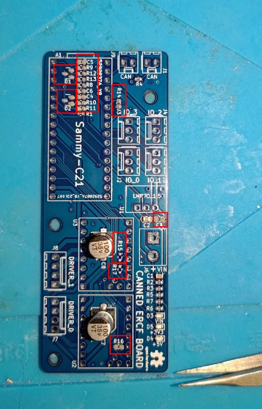
      The components you did not include in the Excel sheet and what I am missing.
      D1, D2
      C3, C4, C6
      R8, R11, R12, R13, R14, R15, R16, R17, R18, R19

      I really hope I am not screwed...

      See my screenshot.
      canned.ercf.so.far.jpg
      smd list.jpg

      posted in Hardware dev
      VoodooBaneundefined
      VoodooBane
    • RE: SAMMYC21 ERCF

      @OwenD Did you make a new Post? I am soldering my own canned ercf board now. Can you share the firmware card you used?

      posted in Hardware dev
      VoodooBaneundefined
      VoodooBane
    • RE: RRF 3.4 Beta 7 | Tool-Offsets Issue

      @sebkritikel I actually figured it out... lol I was doing a negative value on my T1 z-offset. But I changed, I got rid of the negative sign on the Z offset. it is working now. the layers are going down now.

      Only wish I could use a fork of slic3r that allowed you to adjust the z-hop, z-retration, etc in the slicer itself instead of the firmware.

      posted in General Discussion
      VoodooBaneundefined
      VoodooBane
    • RE: RRF 3.4 Beta 7 | Tool-Offsets Issue

      @jay_s_uk Ah yes will do. My mistake. Did mean to hijack anything..lol I will start a new thread. Sorry about that.

      posted in General Discussion
      VoodooBaneundefined
      VoodooBane
    • RE: RRF 3.4 Beta 7 | Tool-Offsets Issue

      Also here are my tool files;

      tfree0.g
      tfree1.g
      tpost0.g
      tpost1.g
      tpre0.g
      tpre1.g

      posted in General Discussion
      VoodooBaneundefined
      VoodooBane
    • RE: RRF 3.4 Beta 7 | Tool-Offsets Issue

      So I am having this issue of the u-axis not having the same Z-height on the X axis .. this is assumed by the T1(the second extruder) not laying down a layer...

      My bed is pretty darn flat. I have both of my Z-axis rods independent and I have them auto tram...

      I figured out that for Slic3r (any kind of Slic3r fork) with RepRap firmware the retractions, Z-lift values, and speeds NEED to be in the setup in RRF firmware, and all of the settings need to be disabled in Slic3r. I do not know how I found this out.

      Source: https://blog.prusa3d.com/slic3r-and-marlin-configuration-for-reprap-firmware-retraction-2_3686/

      I am running a V-cast 1.5 please see the link: https://myhub.autodesk360.com/ue2a0f85b/g/shares/SH35dfcQT936092f0e43f11e68d181475a37
      The only difference to that model is that I am running a different extruder and hot-end.

      Can anyone help me with this problem and find a solution? It seems no one has found a fix or what they did to fix it.

      All my .config files are attached; please tell me if you see something wrong.

      bed.g
      config.g
      homeall.g
      homeu.g
      homex.g
      homey.g
      homez.g

      posted in General Discussion
      VoodooBaneundefined
      VoodooBane
    • RE: Homing Y moves the Z motors + 1LC are not connected not detected

      Update:

      Turns out my Distro board was bad. I just replaced it. Everything is working as it should be now!

      posted in Firmware installation
      VoodooBaneundefined
      VoodooBane
    • RE: Homing Y moves the Z motors + 1LC are not connected not detected

      This Topic has been solved.

      posted in Firmware installation
      VoodooBaneundefined
      VoodooBane
    • RE: Homing Y moves the Z motors + 1LC are not connected not detected

      Nevermind... I wired the 4x conductor connection wrong for the other tool board.

      posted in Firmware installation
      VoodooBaneundefined
      VoodooBane
    • RE: Homing Y moves the Z motors + 1LC are not connected not detected

      @voodoobane said in Homing Y moves the Z motors + 1LC are not connected not detected:

      @jay_s_uk

      I have one more problem... So I can get 1 tool board to detect and register to 121 and I updated the firmware to tool board 3.41 from 3.30. but when I plug the 2nd tool board both do not connect... any ideas? Please and thank you.

      posted in Firmware installation
      VoodooBaneundefined
      VoodooBane
    • RE: Homing Y moves the Z motors + 1LC are not connected not detected

      @jay_s_uk

      That would make a lot of sense...kind feel dumb dumb at the moment... I ha build other printers before and I did seem to have this confusion...lol

      I'll will get back to you ASAP.

      Thank you

      posted in Firmware installation
      VoodooBaneundefined
      VoodooBane
    • RE: Homing Y moves the Z motors + 1LC are not connected not detected

      @jay_s_uk

      Please see the below:

      ; homex.g
      ; called to home the X axis
      ;
      ; generated by RepRapFirmware Configuration Tool v3.3.10 on Sat Jul 09 2022 21:54:56 GMT-0400 (Eastern Daylight Time)
      G91               ; relative positioning
      G1 H2 Z10 F6000   ; lift Z relative to current position
      G1 H1 X-305 F1800 ; move quickly to X axis endstop and stop there (first pass)
      G1 H2 X5 F6000    ; go back a few mm
      G1 H1 X-305 F360  ; move slowly to X axis endstop once more (second pass)
      G1 H2 Z-10 F6000  ; lower Z again
      G90               ; absolute positioning
      
      ; homey.g
      ; called to home the Y axis
      ;
      ; generated by RepRapFirmware Configuration Tool v3.3.10 on Sat Jul 09 2022 21:54:56 GMT-0400 (Eastern Daylight Time)
      G91               ; relative positioning
      G1 H2 Z10 F6000   ; lift Z relative to current position
      G1 H1 Y-305 F1800 ; move quickly to Y axis endstop and stop there (first pass)
      G1 H2 Y5 F6000    ; go back a few mm
      G1 H1 Y-305 F360  ; move slowly to Y axis endstop once more (second pass)
      G1 H2 Z-10 F6000  ; lower Z again
      G90               ; absolute positioning
      
      ; homez.g
      ; called to home the Z axis
      ;
      ; generated by RepRapFirmware Configuration Tool v3.3.10 on Sat Jul 09 2022 21:54:57 GMT-0400 (Eastern Daylight Time)
      G91               ; relative positioning
      G1 H2 Z10 F6000   ; lift Z relative to current position
      G1 H1 Z-305 F1800 ; move Z down until the endstop is triggered
      G92 Z0            ; set Z position to axis minimum (you may want to adjust this)
      
      ; Uncomment the following lines to lift Z after probing
      ;G91              ; relative positioning
      ;G1 Z10 F100      ; lift Z relative to current position
      ;G90              ; absolute positioning
      
      posted in Firmware installation
      VoodooBaneundefined
      VoodooBane
    • Homing Y moves the Z motors + 1LC are not connected not detected

      Hello,

      I am having some problems with my setup of a Duet 3 Mini 5+ with the added Expansion mini 2+. But I also have the tools distro board with two 1LC v1.2. The printer I am building is a V-cast v1.5 so it has two Y-Axis driven with belts.

      So here are my problems;

      My firmware is 3.41

      Problem 1= when I press home Y the two z motors spin. I have edited and tried different drivers sockets and etc.. I am pretty frustrated at this point. I will have my config file posted below:

      ; Configuration file for Duet 3 Mini 5+ (firmware version 3.3)
      ; executed by the firmware on start-up
      ;
      ; generated by RepRapFirmware Configuration Tool v3.3.10 on Tue Jul 19 2022 13:41:07 GMT-0400 (Eastern Daylight Time)
      G4 S1   ;wait 1 second for expansion boards to start
      
      ; General preferences
      ;M575 P1 S1 B57600                                 ; enable support for PanelDue
      M111 S0                    						   ; Debugging off
      G21                       						   ; Work in millimetres
      G90                                                ; send absolute coordinates...
      M83                                                ; ...but relative extruder moves
      M550 P"Matt's IDEX"                                ; set printer name
      
      ; Network
      M552 S1                                            ; enable network
      M586 P0 S1                                         ; enable HTTP
      M586 P1 S0                                         ; disable FTP
      M586 P2 S0                                         ; disable Telnet
      
      ; Drives
      M569 P0.0 S1                                       ; physical drive 0.0 goes forwards X1 motor
      M569 P0.1 S1                                       ; physical drive 0.1 goes forwards X2 motor (U)
      M569 P0.2 S1                                       ; physical drive 0.2 goes forwards Y1 Motor
      M569 P0.3 S1                                       ; physical drive 0.3 goes forwards Y2 Motor
      ;M569 P0.4 S0                                      ; physical drive 0.4 goes forwards
      M569 P0.5 S1                                       ; physical drive 0.5 goes forwards Z1 Motor
      M569 P0.6 S0                                       ; physical drive 0.6 goes backwards Z2 Motor
      M569 P121.0 S1                                     ; physical drive 121.0 goes forwards E0 motor
      M569 P122.0 S1                                     ; physical drive 122.0 goes forwards E1 motor
      
      M584 X0.0 Y0.5:0.6  Z0.2:0.3 U0.1 E121.0:122.0      								; set drive mapping
      M350 X16 Y16:Y16 Z16:Z16 U16 E16:16 I1             									; configure microstepping with interpolation
      M92  X80.00 Y80.00:80.00 Z400.00:Z400.00 U80.00 E562.00:562.00          			; set steps per mm
      M566 X900.00 Y900.00:900.00 Z180.00:Z180.00 U900.00 E120.00:120.00        			; set maximum instantaneous speed changes (mm/min)
      M203 X6000.00 Y6000.00:6000.00 Z180.00:Z180.00 U6000.00 E1200.00:1200.00    		; set maximum speeds (mm/min)
      M201 X500.00 Y500.00:500.00 Z20.00:Z20.00 U500.00 E250.00:250.00       				; set accelerations (mm/s^2)
      M906 X1200 Y1200:Y1200: Z1200:Z1200 U1200 E450:450 I30               				; set motor currents (mA) and motor idle factor in per cent
      M84 S30                                            									; Set idle timeout
      
      ; Axis Limits
      M208 X0 Y0 Z0 S1                                   ; set axis minima
      M208 X300 Y300 Z300 S0                             ; set axis maxima
      M208 X0 Y300 S0                            		   ; set axis maxima Extruder 1 (X0.1)
      M208 X300 Y0 S0                           	 	   ; set axis maxima minima 2 (U0.2)
      
      ; Endstops
      M574 X1 S1 P"!io0.in"                             ; configure switch-type (e.g. microswitch) endstop for low end on X1 via pin !io0.in (X1)
      M574 U2 S1 P"!io1.in"              			      ; configure switch-type (e.g. microswitch) endstop for low end on U2 via pin !io1.in (U2)
      M574 Y0.5:0.6 S1 P"!io2.in"						  ; configure switch-type (e.g. microswitch) endstop for low end on Y via pin !io3.in (Dual Y)
      M574 Z1 S2                                        ; configure Z-probe endstop for low end on Z
      
      
      ; Z-Probe
      M558 P8 C"121.io2.in"  H0.7 F1000 T6000 A20 S0.005  ; SuperPinda probe type to unmodulated and the dive height + speeds
      G31 P500 X0 Y0 Z2.5									; Correct me for 8mm inductive prob - set Z probe trigger value, offset and trigger height (Super Pinda)
      M557 X25:300 Y25:300 S25                            ; define mesh grid
      
      ; Heaters
      M308 S0 P"temp0" Y"thermistor" T100000 B3950       ; configure sensor 0 as thermistor on pin temp0
      M950 H0 C"out0" T0                                 ; create bed heater output on out0 and map it to sensor 0
      M307 H0 B0 S1.00                                   ; disable bang-bang mode for the bed heater and set PWM limit
      M140 H0                                            ; map heated bed to heater 0
      M143 H0 S120                                       ; set temperature limit for heater 0 to 120C
      ;M307 H0 A286.0 C164.4 D2.9 S1.00 V24.0 B0		   ; AC Heater 0 PID adjustment (Heatbed)
      
      
      M308 S1 P"121.temp0" Y"pt1000"                     ; configure sensor 1 as PT1000 on pin 121.temp0
      M950 H1 C"121.out0" T1                             ; create nozzle heater output on 121.out0 and map it to sensor 1
      M307 H1 B0 S1.00                                   ; disable bang-bang mode for heater  and set PWM limit
      M143 H1 S300                                       ; set temperature limit for heater 1 to 300C
      ;M307 H1 A286.0 C164.4 D2.9 S1.00 V24.0 B0	       ; Extruder X1 Heater PID adjustment
      
      
      M308 S2 P"122.temp0" Y"pt1000"                     ; configure sensor 2 as PT1000 on pin 122.temp0
      M950 H2 C"122.out0" T2                             ; create nozzle heater output on 122.out0 and map it to sensor 2
      M307 H2 B0 S1.00                                   ; disable bang-bang mode for heater  and set PWM limit
      M143 H2 S300                                       ; set temperature limit for heater 2 to 300C
      ;M307 H2 A286.0 C164.4 D2.9 S1.00 V24.0 B0	       ; Extruder X2 Heater PID adjustment
      
      ; Fans
      M950 F0 C"121.out1" Q500                           ; create fan 0 on pin 121.out1 and set its frequency
      M106 P0 C"Heatsink fan 1" S1 H1 T45                ; set fan 0 name and value. Thermostatic control is turned on
      M950 F1 C"121.out2" Q500                           ; create fan 1 on pin 121.out2 and set its frequency
      M106 P1 C"Part cooling 1" S1 H-1                   ; set fan 1 name and value. Thermostatic control is turned off
      M950 F2 C"122.out1" Q500                           ; create fan 2 on pin 122.out1 and set its frequency
      M106 P2 C"Heatsink fan 2" S1 H2 T45                ; set fan 2 name and value. Thermostatic control is turned on
      M950 F3 C"122.out2" Q500                           ; create fan 3 on pin 122.out2 and set its frequency
      M106 P3 C"Part cooling 2" S1 H-1                   ; set fan 3 name and value. Thermostatic control is turned off
      
      ; Tools
      M563 P0 S"Extruder 1" D0 H1 F0:1                   ; define tool 0
      G10 P0 X0 Y0 Z0                                    ; set tool 0 axis offsets
      G10 P0 R0 S0                                       ; set initial tool 0 active and standby temperatures to 0C
      M563 P1 S"Extruder 2" D1 H2 F0:3                   ; define tool 1
      G10 P1 X0 Y0 Z0                                    ; set tool 1 axis offsets
      G10 P1 R0 S0                                       ; set initial tool 1 active and standby temperatures to 0C
      
      ; Miscellaneous
      
      
      ;NeoPixel LED Stip
      M150 X3 Q3000000     								 ; set LED type to NeoPixel and set SPI frequency to 3MHz
      M150 B255 P255 S30 f0    							 ; set first ALL (30) LEDs to Blue, half brightness
      
      ; Panic power loss and Resume
      M911 S20 R22 P"M913 X0 Y0 G91 M83 G1 Z3 E-5 F1000"   ; set voltage thresholds and actions to run on power loss
      

      Problem 2= 121 and 122 are not being detecting. they keep timing out.
      If I click "run config file" after saying the errors are below:

      9/5/2022, 7:53:04 PM 	Error: Response timeout: CAN addr 122, req type 6027, RID=50
      Error: Fan number 2 not found
      Error: Response timeout: CAN addr 122, req type 6027, RID=52
      Error: Fan number 3 not found
      9/5/2022, 7:52:58 PM 	Error: Response timeout: CAN addr 122, req type 6026, RID=44
      Error: Heater 2 not found
      Error: Heater 2 does not exist
      Error: Response timeout: CAN addr 121, req type 6027, RID=46
      Error: Fan number 0 not found
      9/5/2022, 7:52:50 PM 	Error: Response timeout: CAN addr 121, req type 6031, RID=38
      9/5/2022, 7:52:43 PM 	Error: Response timeout: CAN addr 121, req type 6042, RID=31
      Response timeout: CAN addr 122, req type 6042, RID=32
      9/5/2022, 7:52:41 PM 	Error: Response timeout: CAN addr 121, req type 6042, RID=29
      Response timeout: CAN addr 122, req type 6042, RID=30
      9/5/2022, 7:52:39 PM 	Error: Response timeout: CAN addr 122, req type 6018, RID=28
      9/5/2022, 7:52:38 PM 	Error: Response timeout: CAN addr 121, req type 6018, RID=27
      

      Important note via diag LEDS: The 122 toolboard is flashing fast red with solid blue light. But the 121 toolboard is just solid blue light. Doing a m115 command shows them not connected.

      Please note:
      -I have used a multimeter to check the connection on the Bus cable which is a twisted ribbon cable (2 wires) + "RJ-12" , connectors I crimped it myself. This checked it via continuity test and it is good

      -I have checked the connections with the 4 x small connector from the tool boards to the distro board(the jumpers ARE removed for the ones in use) This checked it via continuity test and it is good

      I guess the thing to start with Problem 1. Then go from there.

      Thank you so much for your help!
      posted in Firmware installation
      VoodooBaneundefined
      VoodooBane
    • RE: e3d TC coupler motor is not moving and homing C has no errors?

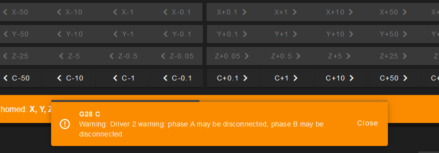
      @dc42 I figured it out... Driver 2 is bad...

      posted in General Discussion
      VoodooBaneundefined
      VoodooBane
    • RE: e3d TC coupler motor is not moving and homing C has no errors?

      @dc42 I using Version 3.4

      Capture.PNG

      posted in General Discussion
      VoodooBaneundefined
      VoodooBane
    • RE: e3d TC coupler motor is not moving and homing C has no errors?

      @voodoobane I checked the A and B poles and they are correct.

      posted in General Discussion
      VoodooBaneundefined
      VoodooBane
    • RE: e3d TC coupler motor is not moving and homing C has no errors?

      @rushmere3d

      All I see is the homeC.
      But no I have another problem

      Is it normal if this isn't all set to have the Home C tell me the wiring is wrong? I have a 2nd motor just in case. and it gives me the same error. I double-checked my wiring and everything. I do not understand it is saying my wiring is bad. could s0 and s1 be a factor? I have little information about this tool changer motor.

      posted in General Discussion
      VoodooBaneundefined
      VoodooBane
    • RE: e3d TC coupler motor is not moving and homing C has no errors?

      I will try this guys!

      posted in General Discussion
      VoodooBaneundefined
      VoodooBane