In case anybody else is having this issue and their Duet is buried inside their printer where the SD card isn't accessible, you can create the directory from the Web UI by navigating to this URL: (Replace <DuetIP> with the IP address of your duet)
http://<DuetIP>/rr_mkdir?dir=0%3A%2Ffilaments
Best posts made by yngndrw
-
RE: Error: Failed to create directory 0:/filaments/PLAposted in My Duet controlled machine
-
RE: PrintEye; simple information panel for Duet boards.posted in General Discussion
@EasyTarget No worries, I'm sorry my message came across badly - It was probably not the best judgement for my first post on here in years to be a "have you considered X hardware" post. The issue only came to mind because I'd recently used an RP2040 (Specifically the W5500-EVB-Pico, a fantastic board if you need ethernet in a project) on a commercial project and hit the memory limit a number of times. At the end of the day the "right" thing to use is whatever you're comfortable with - It's all personal preference as long as you're aware of the limits and trade-offs.
-
RE: RepRapFirmware road map Q1 2021posted in Future Direction
Very excited about the input shaping, especially after this video was released yesterday:
https://www.youtube.com/watch?v=6JBIEJan6zs&ab_channel=Vez3D -
RE: Warning to users of servomotors!posted in Using Duet Controllers
Back in the days of GeckoDrive, they documented a simple circuit to clamp the supply in situations like this:
https://www.geckodrive.com/support/returned-energy-dump.htmlI'm thinking that a sufficiently sized TVS diode would would resolve the issue, although given that the JMC iHSV servos are rated up to 50V with 36V nominal, you're probably better running them at 36V separate from the Duet anyway as suggested above.
-
RE: PrintEye; simple information panel for Duet boards.posted in General Discussion
@EasyTarget You may want to consider an ESP32 over the RP2040. I adore the RP2040 and use it whenever I can but I often find that for projects which involve a lot of JSON, the memory limit becomes an issue. The ESP32 has the advantage that it can use external memory, whilst still being a modern dual-core microcontroller.
-
RE: CNC-Specific Boardposted in Hardware dev
@o_lampe
Yes that's what I meant about not allowing remote resetting. You should need to physically return to the machine in order to reset and re-arm the machine.I think from a software point of view, this means that there should be slightly different terminology within the software. You can trigger the emergency stop and you can clear the fault from the software's point of view, but you cannot reset the emergency stop from there. From a documentation point of view, I'd try to push people down the route of using a real safety relay with redundancy and dual channel emergency stops.
I'd recommend #5 from my list above for your machine if your drivers support it, it should be the easiest to configure and it will prevent burning out motors / drives and destroying mechanical parts if the same thing happens again. (Or at least, it will in some scenarios!)
-
RE: Advice on adding plasma torch height controlposted in Firmware developers
I'm also wondering if there has been are work on this area, I couldn't see much in the forums about THC aside from another thread about an external controller.
Hypertherm provide some cut charts showing the sort of values expected for pierce height, pierce delay, nominal heights and feed rates. (Attached)
GDE_810050_R0_Duramax_Cut_Charts_Powermax45.pdfIn addition to their normal CNC interface (Divided arc voltage output, trigger input, arc transfer/okay output) they also have a second serial interface for additional information and control. (E.g: Mode, current set, actual current, type of nozzle) (Also attached)
GDE_810400_R2.pdfI really like the Duet3D platform and would love to use it for my upcoming CNC plasma cutter build.
-
RE: Soldering/Hot Air Station - What are these for?posted in Off Topic
@richardmckenna To me it looks like a stand. If you rotate the wire part 180 degrees, put the screw through the narrow part and into the hold on the bar, you end up with a sort of tuning fork shape.
That's my guess anyway. Did it not come with a manual or some pictures of it in its assembled state?
Edit:
Just found this which shows it assembled:

Not sure what it's for though, maybe it's for poking people who interrupt your soldering session?
-
RE: PrintEye; simple information panel for Duet boards.posted in General Discussion
@EasyTarget I'm just advising that memory might become an issue for the JSON parsing, that's all. I did say I adore the RP2040, it's my go-to when memory isn't an issue - They all have their place. I'll keep to myself next time, sorry to bother you.
-
RE: PrintEye; simple information panel for Duet boards.posted in General Discussion
@dc42 said in PrintEye; simple information panel for Duet boards.:
@yngndrw said in PrintEye; simple information panel for Duet boards.:
I'm just advising that memory might become an issue for the JSON parsing, that's all
You might like to look at the PanelDueFirmware code on github. It uses a Json parser that uses minimal RAM.
Ohh I didn't notice that library, I'll have to give JSMN a try in my own projects! Thanks.
Latest posts made by yngndrw
-
RE: Advice on adding plasma torch height controlposted in Firmware developers
@o_lampe said in Advice on adding plasma torch height control:
@yngndrw said in Advice on adding plasma torch height control:
Moving a bed, complete with water, doesn't sound like fun. Aside from the mass, you'd also have to deal with the sloshing.I'm doing the trick with a submerged inflatable tire-tube to lower the water level for transport. It's also the easiest way to adjust water level while cutting
I mean when the bed is moving, not when you're transporting the machine. Unless it's moving really slowly, the water will be sloshing out whenever it changes direction.@OwenD said in Advice on adding plasma torch height control:
@yngndrw
I think that 40mm is too shallow for a water table even at 40 amps
The compressed air will blow it out.
You'll need to look at 100-150mm in depth.
If the air pushes aside the water all the way to the bottom it won't trap any fumes. Plus it'll splash everywhere.Industrial filters capture particles small enough to directly enter the blood stream via the lungs.
It's not just dust, there are factors such as hexavalent chrome etc.
You should read here for a start
https://www.kemper.eu/en/worth-knowing/welding-smoke-regulations-and-legistlation/1.-overview
The KEMPER filters for cnc tables have a self cleaning system as well.As far as slats go, all they have to be is ordinary flat mild steel. 50 x 3 would suffice. If they're 76 or 100 you can flip them as they are damaged.
The usual arrangement is the have three vertical pieces of flat running lengthways down the table.
These have slots in them about every 50mm.
When you put your slats in, you bend them in a curve so that the middle is 50mm further up than the ends.
This stops cross cuts being on top of a slat for long.
All the slats can then be the same length.
Ah that's good to know, I suppose I'll have to make my own deep water table then.I did look at water scrubbers for a downdraft table after realising how simple they are, but then I realised the airflow requirements are silly even for a modest table. For a 0.5 square meter table, Hypertherm is suggesting over 3000 cubic meters per hour which is an order of magnitude larger than "metal dust collectors" I can find. It's therefore unreasonable to try to move that volume of air, especially if you're trying to filter it to say 1-3 microns. In fact, it gets to the point where the downdraft fan motor draws more power than the plasma cutter, which added to the air compressor will be too much for my workshop. Hexavalent chrome appears to require 5-micron filtration and I'd really like to be able to work with stainless, so I think the water table option is more reasonable.
I'll probably aim for a tray depth of 150mm and a water/slat level of 100mm to prevent splashing. I just need to work out how to build it.
-
RE: Advice on adding plasma torch height controlposted in Firmware developers
@OwenD Thanks for the software suggestions, I'll have a look into those.
I wasn't aware of the explosion risk with aluminium and water, that's good to know. What filtration systems do the industrial downdraft systems use? I'm wondering if a DIY version can be made for a smaller work area with sufficient flow.
@o_lampe I don't know if this is any help for your project but I always try to start designing around the bits I want to buy in. In my case that's the magnetic breakaway torch holder (I have not found one yet) and the water table (As I have zero confidence that my welds won't leak!)
For the water table I've been looking at these 1000x500x40mm stainless trays:
https://www.amazon.co.uk/dp/B0CFV84HZG/?th=1... Along with these packs of slats:
https://www.ebay.co.uk/itm/196266001091I'd rather use a taller water table, but it's the right size for the pre-made slats to have a slight curve. My plan was to add a slotted angle frame on the inside to hold the slats and they are easy to replace with off-the-shelf items.
Moving a bed, complete with water, doesn't sound like fun. Aside from the mass, you'd also have to deal with the sloshing.
-
RE: Advice on adding plasma torch height controlposted in Firmware developers
@OwenD Thank you for this, it's always interesting to hear about how things are done on production systems.
I don't personally baulk at paying for software, as long as it's affordable. The issue is that sometimes the software is only priced for large industry players where there's no suitable pricing model for hobbyists. Do you have any suggestions for software at this sort of level? Sheetcam appears to be commonly used at our level, but I'm finding it difficult to work out exactly what its capabilities are as their website is rather light on detail.
On fume extraction, do you have any suggestions on what approach to go for - For a smaller, hobby-use system? The main approaches appear to be downdraft or a water table, but each appears to have serious downsides:
- Downdraft, how do you filter the air if you don't want to just dump it outside? I've not yet seen a filter design which wouldn't clog almost instantly.
- Water table, cleanup is a pain, as is the problem of stale water over time. Some people filter their water, but I'm not convinced about filter clogging for this either as the particulates appear to be extremely fine and there's very little in terms of information about the long-term performance of the various filter designs.
-
RE: Advice on adding plasma torch height controlposted in Firmware developers
@o_lampe My gut feeling was that, like in 3D printing, the material section would be the responsibility of the CAM (Slicer) but looking into it, it does typically appear to be the THC that has control over this.
Here's a screenshot from the Centroid THC profile manager:
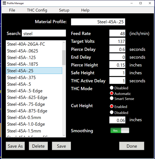
It's interesting because as OwenD mentioned above, the feed rate depends on the cornering so in reality both the CAM and the THC need to know about the material.
If the THC does need this information, then I think you're right that the filament system is the appropriate place.
Hypertherm do provide timing diagrams for moving piercing on the much larger systems, so I've asked if they have the same diagrams for standard piercing on smaller machines:
https://www.hypertherm.com/Download?fileId=HYP113984&zip=False -
RE: Advice on adding plasma torch height controlposted in Firmware developers
I'm also wondering if there has been are work on this area, I couldn't see much in the forums about THC aside from another thread about an external controller.
Hypertherm provide some cut charts showing the sort of values expected for pierce height, pierce delay, nominal heights and feed rates. (Attached)
GDE_810050_R0_Duramax_Cut_Charts_Powermax45.pdfIn addition to their normal CNC interface (Divided arc voltage output, trigger input, arc transfer/okay output) they also have a second serial interface for additional information and control. (E.g: Mode, current set, actual current, type of nozzle) (Also attached)
GDE_810400_R2.pdfI really like the Duet3D platform and would love to use it for my upcoming CNC plasma cutter build.
-
RE: PrintEye; simple information panel for Duet boards.posted in General Discussion
@dc42 said in PrintEye; simple information panel for Duet boards.:
@yngndrw said in PrintEye; simple information panel for Duet boards.:
I'm just advising that memory might become an issue for the JSON parsing, that's all
You might like to look at the PanelDueFirmware code on github. It uses a Json parser that uses minimal RAM.
Ohh I didn't notice that library, I'll have to give JSMN a try in my own projects! Thanks.
-
RE: PrintEye; simple information panel for Duet boards.posted in General Discussion
@EasyTarget No worries, I'm sorry my message came across badly - It was probably not the best judgement for my first post on here in years to be a "have you considered X hardware" post. The issue only came to mind because I'd recently used an RP2040 (Specifically the W5500-EVB-Pico, a fantastic board if you need ethernet in a project) on a commercial project and hit the memory limit a number of times. At the end of the day the "right" thing to use is whatever you're comfortable with - It's all personal preference as long as you're aware of the limits and trade-offs.
-
RE: PrintEye; simple information panel for Duet boards.posted in General Discussion
@EasyTarget I'm just advising that memory might become an issue for the JSON parsing, that's all. I did say I adore the RP2040, it's my go-to when memory isn't an issue - They all have their place. I'll keep to myself next time, sorry to bother you.
-
RE: PrintEye; simple information panel for Duet boards.posted in General Discussion
@EasyTarget You may want to consider an ESP32 over the RP2040. I adore the RP2040 and use it whenever I can but I often find that for projects which involve a lot of JSON, the memory limit becomes an issue. The ESP32 has the advantage that it can use external memory, whilst still being a modern dual-core microcontroller.
-
1XD with encoder inputs (Homing based on incremental encoders)posted in Hardware wishlist
Hello,
The 1XD board is a great step towards proper servo drives for CNC usage. With a proper AC servo which has closed loop control between the motor and the driver, end-to-end closed loop control isn't really needed especially if the error/fault output of the servo drive is used. There is however a second use for encoder inputs - Homing.
Proper servo drives often have buffered encoder outputs, which are the full complement of encoder signals including the index. If a "course" homing switch is included on the axis to get within one motor revolution of the final home location, the final homing can be completed using the encoder by allowing it to continue rotating in a given direction until the index signal is raised. This is far more repeatable than a homing switch (Subject to backlash) and operates with the same resolution of the servo motor.
Obviously this also puts in the ground-work for end-to-end closed loop control with external drivers if that's implemented.
So my proposal is to build another version of the 1XD with some more I/O:
- 3x differential driver outputs: Step/Direction/Enable [As it currently has]
- 1x high-current brake output [As it currently has]
- 3x differential encoder inputs: A/B/I
- 1x differential error/fault input
- 2x single-ended endstop inputs (Can be GPIO) [As it currently has]
See page #57 for an example encoder output from a servo drive:
https://www.applied-motion.com/sites/default/files/hardware-manuals/SV200_AC_Hardware_Manual_920-0096H.pdfThe other option of course is something like EtherCat, but that's a whole separate topic.
Thanks,
-Andrew.