slant lines
-
@arhi said in slant lines:
You sure? I know the original design I had was holding both bearings strongly
the top bearing doesn't hold the worm gear, it is just leaning on it. so if the shaft end is just slightly bent the top bearing will help very little.
@arhi said in slant lines:
I'd up the current on the extruder motor to try out that too
I'm afraid I tried that already
-
@matt3o yes, I opened it up .. the worm is not going in the top bearing
 .. dunno if the top bearing is tight around the flex ... anyhow, I don't have slant lines with flex3drive+e3d, had with flex3drive+mellow. you have it now without flex so there must be something else
 -
okay, it took me a while but I reprinted all the pieces of my printer with a stronger filament. Changed motors. Changed pulleys and idlers and checked them with a dial gauge. Tried various belt tensions.
The result is always the same and it's very frustrating.
The only things left to try are the leadscrews (which I ordered but with covid19 who knows when I got them) and wires. Could it be interference? I connected all motors and rails to the frame and then to ground, so that is covered.
It really looks like a problem with the extruder but I get the same issue with all the extruders I feed to it. So I'm really out of clues now.
-
@matt3o, not sure what you have already tested but if you think it's extruder related, you can try changing the extrusion width in your slicer and see if it changes the slope of the slanted lines.
My thinking is that if its' something cyclic in the extruder, changing the width will change the x/y length per extruder cycle.
Does this make sense?
-
The pattern is related to worm drive systems in general, and teeth engagement. There are a few folks that have done quite a bit of analysis, and the harmonic is repeatable, and is a factor of the contact/engagement pulses that occur as the teeth engage, flex, and transition to the next, in concert with the worm gear. I can scrounge up some of the data and graphics that support this.
-
Here’s the issue in more detail.
Ignore the name references, they are to people in a troubleshooting forum.
It seems that all pieces start to fit together. Mr X made great movies of which especially the one from yesterday sounded like 40 load variations over a full revolution of the extruding gear. With the 1:20 gear ratio that indicated some loading effect every half a turn of the worm wheel.
Mr Y made a nice Excel sheet computing the amount of filament extruded over the ripple length and related this to the amount of rotation of the stepper motor and hence also the worm wheel. After some additional testing on the length of the ripple and amount of filament, the Excel pointed to about 1/2 a turn of the worm as well.
Furthermore we know that within reason the ripple is print speed independent, pointing to a mechanical issue as well. Hence the gearing is suspect from that point of view too.
So in rotational analysis one can say it seems there is a second order / harmonic rotation (un)uniformity on the worm wheel. What can be the case?
Alignment etc:
Basically all alignment issues etc typically point only to the first order / harmonic and seen in "unbalance". As we see a second order phenomenon, we can largely rule out these kind of effects.Production:
Looking at the worm wheel shape one might then argue it is "not round" but has a fluctuation in its size over rotation different from its ideal shape. So this can happen with the injection molding of the gear, but it turns out that the mold has three parts, so some cooling issue would be visible not in the second but 3rd order. Also there is one injection channel, meaning this woild result in a first order and also not second.Stiffness effect:
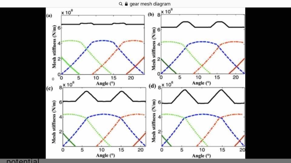
From here on the suspect went to the stiffness effect of the gear set. Some literature example of the effect on the stiffness of the tooth on rotation uniformity is seen in the figure.Basically there are on average 2 teeth continously engaged with the worm gear set. Take the blue line: this is the engagement of 1 tooth over a full rotation of the worm (as after one rev we are to the next tooth).
The green and red are the adjacent teeth that are also (partly) engaged with the blue one. Together the make a stiffness from incoming shaft to outgoing. That stiffness is the black line.
As seen the stiffness over a rotation of the worm changes two times, hence second order!
The change in stiffness has the effect that in the lower stiffness region the teeth are compressed and the outgoing shaft lacks a little behind. Moving to the stiffer part the "spring energy" is given back to the rotation and the outgoing shaft advances again.
This therefore gives a pressure fluctuation in the nozzle and results in the ripple.
The 4 diagrams show how this second order effect increases when stiffness of teeth get lower.
-
@Nuramori wow, that's very interesting. Thanks for sharing... but... I tried to print with a bondtech extruder and I get that pattern too.
I also tried to slice with different slicers and I get different results but still slant lines.
PrusaSlicer
Cura
Everything seems to point to the extruder, but why I get the slant lines with every extruder I use?
@zapta yeah, I tried various layer heights and the lines indeed change.
-
I made one more test, printing the cube at 45deg to check my motion system (corexy) and the outcome is exactly the same. So it doesn't really look like a mechanical issue.
could it be that my motion system is so well tuned that it emphasizes the extruder "signature"?
-
@matt3o I don't think you ever posted your config.g (or at least, I can't find it). Can you post that? And firmware version? Send M115 and post response.
Ian
Bed-slinger - Mini5+ WiFi/1LC | RRP Fisher v1 - D2 WiFi | Polargraph - D2 WiFi | TronXY X5S - 6HC/Roto | CNC router - 6HC | Tractus3D T1250 - D2 Eth
-
@droftarts you are totally right.
Of course many parameters change based on the extruder that I'm using.
FIRMWARE_NAME: RepRapFirmware for Duet 2 WiFi/Ethernet FIRMWARE_VERSION: 2.04 ELECTRONICS: Duet WiFi 1.02 or later + DueX5 FIRMWARE_DATE: 2019-11-01b1; General ; -------------------------------------------------- M111 S0 ; Debug off M550 PCorezilla ; Machine name and Netbios name (can be anything you like) M551 Preprap ; Machine password (used for FTP) M552 S1 ; Turn network on ;M586 P1 S1 ; Enable FTP M555 P2 ; Set output to look like Marlin G21 ; Work in millimetres G90 ; Send absolute coordinates... M83 ; ...but relative extruder moves M669 K1 ; CoreXY mode ; Motors configuration ; -------------------------------------------------- M584 X0 Y1 Z2:3:4 E6 ; set drive mapping M569 P0 S1 ; Drive 0 goes backwards | X stepper M569 P1 S1 ; Drive 1 goes backwards | Y stepper M569 P2 S0 ; Drive 2 goes forwards | Z stepper - Z1 M569 P3 S0 ; Drive 3 goes forwards | E0 stepper - Z2 M569 P4 S0 ; Drive 4 goes forwards | E1 stepper - Z3 M569 P5 S1 ; Drive 5 goes forwards | extruder M350 X16 Y16 I1 M350 Z16 I1 M350 E16 I1 M92 X160 Y160 Z1600 E415 ; Steps/mm M906 X1400 Y1400 Z1400 E500 I60 ; set motor currents (mA), motor idle factor (%) M201 X2000 Y2000 Z20 E200 ; set accelerations (mm/s^2) M203 X12000 Y12000 Z600 E1200 ; set maximum speeds (mm/min) M566 X720 Y720 Z15 E6 ; maximum jerk speeds (mm/min) ; Axis limit and endstops ; -------------------------------------------------- M208 X0:406 Y0:390 Z0:390 ; set axis limits M574 X1 Y1 S1 ; set active high endstops M574 Z1 S2 ; set endstops controlled by probe ; Z-Probe M558 P1 I0 H5 R0.4 F400 T6000 ; set Z probe type to effector and the dive height + speeds G31 P543 X0 Y0 Z-0.1 ; set Z probe trigger value, offset and trigger height M557 X20:370 Y20:370 S50 ; define mesh grid ; Leadscrew locations M671 X428.4:-31.5:198.4 Y38.5:38.5:413.5 S25 ; Tools: Heaters, thermistors and fans ; -------------------------------------------------- M305 P0 S"Bed" T100000 B3950 R4700 H0 L0 ; Bed thermistor M305 P3 S"E0" T500000 B4723 C1.196220e-7 R4700 H6 L0 ; E0 thermistor M570 S180 ; Hotend may be a little slow to heat up so allow it 180 seconds M143 H0 S120 ; Maximum H0 (Bed) heater temperature M143 H3 S290 ; Maximum extruder 3 heater temperature ; Adjustments heaters M307 H0 A301.3 C836.5 D0.9 B1 ; bed heater M307 H3 A646.6 C192.9 D3.8 B0 ; tool 0 heater ; Fans M106 P3 T45 H3 ; Enable thermostatic mode for fan 3 on heater 3 M106 P4 H-1 ; Disable thermostatic mode for fan 4 (part fan) M106 P4 S0 ; Tool definitions M563 P0 D0 H3 F4 ; Define tool 0 heater 3 fan 4 G10 P0 S0 R0 ; Set tool 0 operating and standby temperatures ; Closing ; -------------------------------------------------- M208 S1 Z-0.2 ; set minimum Z T0 ; select first hot end -
Add
M569 P6 S1after the other drives, but I don’t think that will make much difference.Ian
Bed-slinger - Mini5+ WiFi/1LC | RRP Fisher v1 - D2 WiFi | Polargraph - D2 WiFi | TronXY X5S - 6HC/Roto | CNC router - 6HC | Tractus3D T1250 - D2 Eth
-
@droftarts yeah that comes from testing various stepper drivers. Usually it's on E5. It makes no difference but thanks for checking that out
-
@matt3o You could also update to 2.05.1. Again, probably won't make a difference, but would be good to see if it changes anything.
The other thing I'd do is swap the bed motors to the Duex, and use the Duet for X, Y and E. eg
M584 X0 Y1 Z5:6:7 E3. This will check it's a comms issue between the Duet and Duex. I don't know if you've always been using the Duex for the extruder, or have tested it the other way around, though.Ian
Bed-slinger - Mini5+ WiFi/1LC | RRP Fisher v1 - D2 WiFi | Polargraph - D2 WiFi | TronXY X5S - 6HC/Roto | CNC router - 6HC | Tractus3D T1250 - D2 Eth
-
@droftarts I'll update to v3 tomorrow, I already have the updated config, I just wanted to to fix this issue first, but I guess it's worth trying upgrade the duet.
In the various tests I've done I believe I also tried a stepper on the duet for the extruder moving one of the other axis on the duex.
I think it's worth trying a completely new controller, since that is the only thing that I haven't tried to change at this point. Not that it's a good time to buy 3d printing stuff with coronavirus and all.
-
@matt3o I have to ask... is this a clone or genuine Duet? If it's genuine, and swapping the board fixes the problem, and the board is less than 6 months old (from your first post in this thread) it should be covered by the warranty.
Ian
Bed-slinger - Mini5+ WiFi/1LC | RRP Fisher v1 - D2 WiFi | Polargraph - D2 WiFi | TronXY X5S - 6HC/Roto | CNC router - 6HC | Tractus3D T1250 - D2 Eth
-
@matt3o said in slant lines:
could it be that my motion system is so well tuned that it emphasizes the extruder "signature"?
I think you might be right. In my experience many extruders have a very small periodic error. In most cases it is not visible. It depends on what hotend you have too, I would guess that if the "melt-pot" is big it will provide some elasticity inside the hot end.
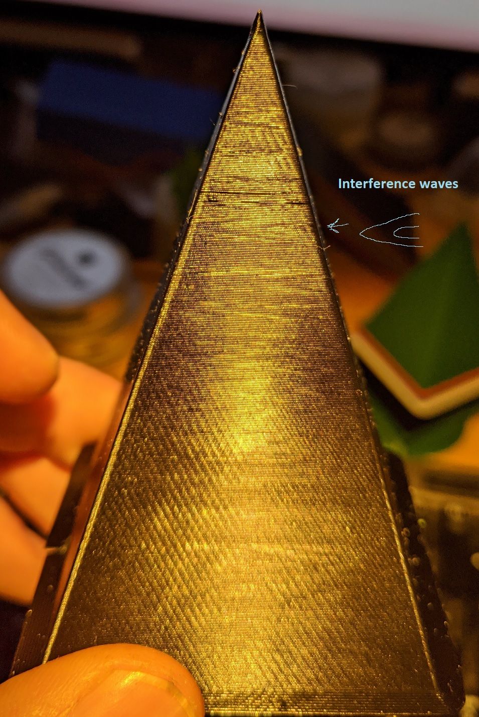
My standard test object is a square cone in vase made. It is very good for showing periodic extrusion errors and mechanical errors. The varying of the extrusion length over height of the cone will make periodic extrusion errors show up very clearly as interference patterns.
Even a BMG through a 50cm bowden tube shows extrusion errors (ignore the slant lines in this case, they are mechanical). The errors in this case are so small that in any normal case it is totally invisible, this test provokes it.
-
@droftarts hey! of course it's a genuine duet!
 we are not lamerino here!
  BTW, I'm not covered by the warranty because I modded the wifi module.
@bondus said in slant lines:
I think you might be right. In my experience many extruders have a very small periodic error. In most cases it is not visible. It depends on what hotend you have too, I would guess that if the "melt-pot" is big it will provide some elasticity inside the hot end.
yeah that's my thought too... I'll also try a different hotend (mosquito right now).
-
Quick update. I replaced the mosquito with an E3D hotend (also thermistor and heater). The texture changed again but I still get the slant lines pattern.
So at this point the only element left to change is the controller... It will take some time to get my hands on a new controller with the current covid19 situation but I'll update as soon as I get it.
-
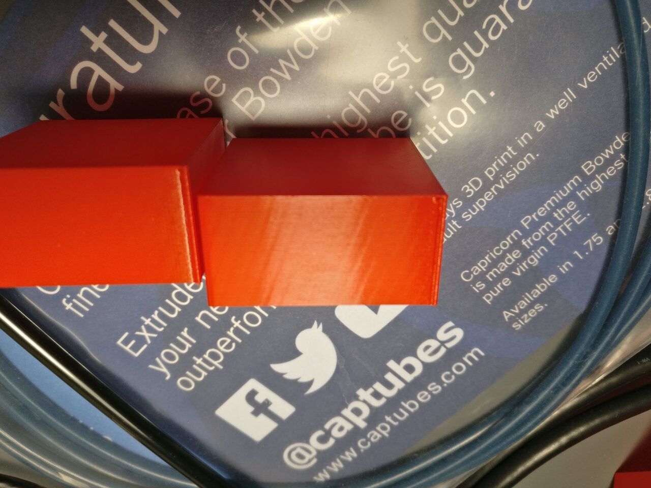
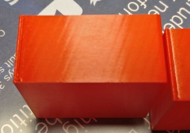
It took me a while but I wanted to give a closure to this issue in case someone ends up here from google or forum search.
The following is my current status, printed at 100mm/s with 4500 acceleration.
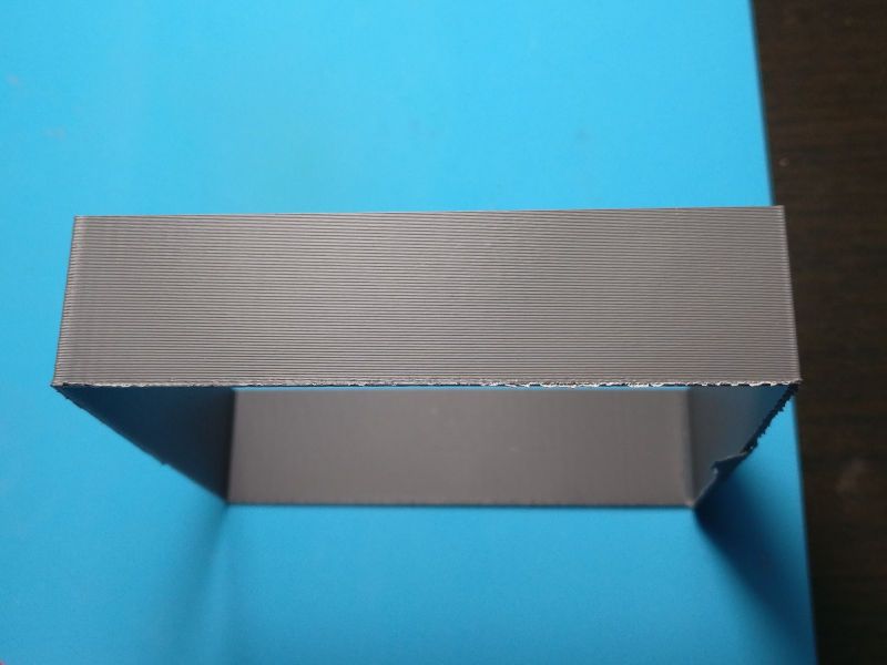
There are still a few issues that I'm trying to fix, but things are slowly getting better.
This is a corexy, they are heinous machines. Do yourself a favor and build a Cartesian
The bare minimum you need:
- super steady frame
- good vibration abortion
- study gantry, use metal to hold the gantry if you can, otherwise 3d print big brackets and add more screws than you think it's necessary
- tight belts
- don't spare on pulleys and idlers, get good and correctly sized shims between the idlers. I got "precision shims" but they were a little rough on the edges and I had to file all of them
- after you first assembled the machine, give your screws another go, for some reason they like to loosen up
- proper part cooling (duh)
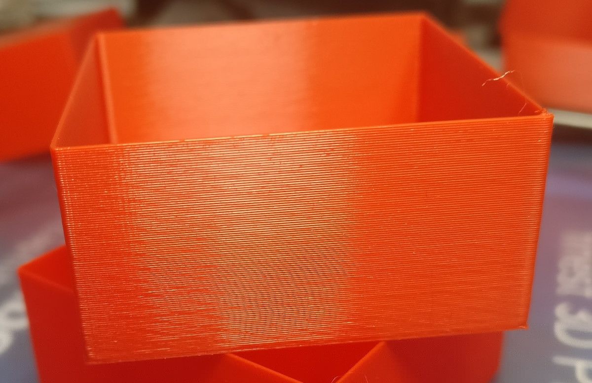
I've rebuilt my printer with all of the above in mind, and that helped to reach relatively high speed/acceleration but what really helped with the slant texture is... tune your extruder/hotend.
When the machine is overall well calibrated you are going to see every little defect generated by the extruder/hotend. Even an over-extrusion of 1% or a +2-3°C in temp can generate a bad surface texture.
Try to slice with different slicers (Cura seems a little less finicky) or change from Relative to Absolute (or vice versa) extrusion.
If tests and benchmarks say that your motor is calibrated properly but you still see a slanted texture, don't trust them and start lowering the extrusion multiplier and/or the temperature. You'll be surprised by how much of a difference a 1% does.
If the surface still look bad, try to change the extruder motor. I've been lucky with both 0.9° Nema17 and 1.8° Nema14 from LDO. I had a few issues with moons on the extruder, while they are great on XYZ.
Edit: almost forgot! Align your rails. Get a precision gauge and align your rails. When they are aligned, aligned them again
Hope that helps. Happy printing.