Trying to remove tiny holes/gaps on layers...
-
I am in the process of setting up my first 3D Printer (a Cetus 3D MKII with Duet 2 Maestro (Firmware 3.1.1) + BLTouch 3.1). Overall things are going well. I am now trying to dial in the settings to get nice prints but hitting a few road blocks.
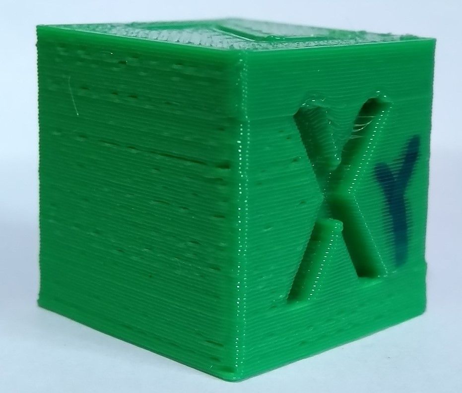
I am currently printing a Calibration Cube. The printed dimensions seems to be near spot on ~20mm however I keep getting tiny holes/gaps on some areas of the print (see image below). Does anyone know why this would be happening and how I can go about fixing it?
Filament is PETG printed at 235C first layer and 230C all other layers.
Retraction speed: 133.3 mm/s
Retraction length: 1.8mm
Layer height: 0.25
Nozzle: 0.4
Extrusion width = 0.45mm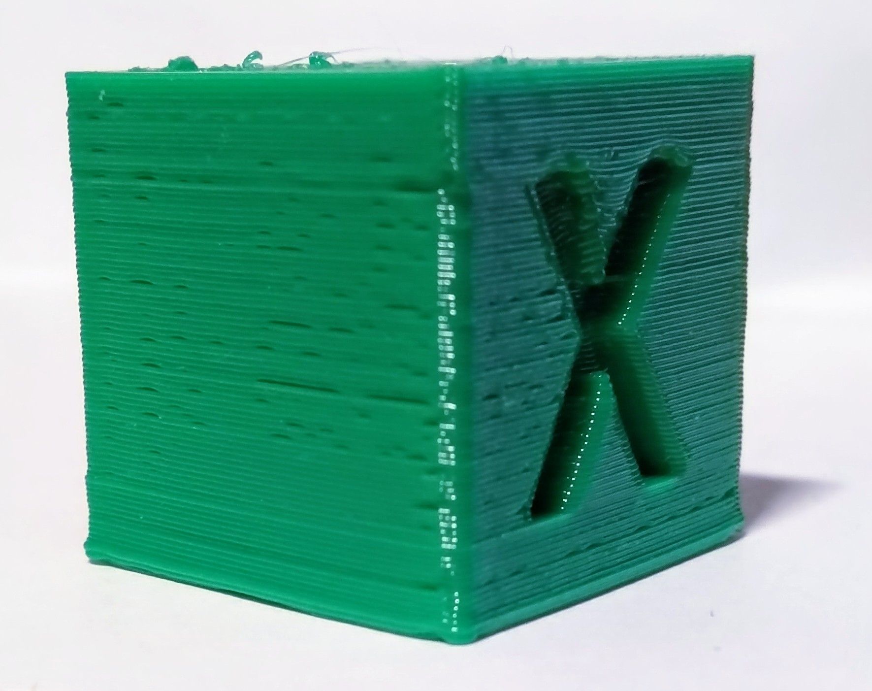
My config.g
; Configuration file for Duet Maestro (firmware version 3) ; General preferences G90 ; send absolute coordinates... M83 ; ...but relative extruder moves M550 P"Duet Cetus" ; set printer name ; Drives M569 P0 S0 ; physical drive 0 goes backwards M569 P1 S1 ; physical drive 1 goes forwards M569 P2 S1 ; physical drive 2 goes forwards M569 P3 S0 ; physical drive 3 goes backwards M584 X0 Y1 Z2 E3 ; set drive mapping M350 X256 Y256 Z256 E256 I0 ; configure microstepping without interpolation M92 X1280.00 Y1280.00 Z1280.00 E1877.77 ; set steps per mm (E1650) M566 X39000.00 Y39000.00 Z39000.00 E7200.00 ; set maximum instantaneous speed (jerk) changes (mm/min) M203 X420000.00 Y420000.00 Z420000.00 E420000.00 ; set maximum speeds (mm/min) M201 X1000.00 Y1000.00 Z1000.00 E1000.00 ; set accelerations (mm/s^2) M906 X450 Y450 Z450 E400 I30 ; set motor currents (mA) and motor idle factor in per cent M84 S30 ; Set idle timeout ; Axis Limits M208 X0 Y0 Z0 S1 ; set axis minima M208 X180 Y180 Z181.35 S0 ; set axis maxima ; Endstops M574 X1 S1 P"xstop" ; configure active-high endstop for low end on X via pin xstop M574 Y1 S1 P"ystop" ; configure active-high endstop for low end on Y via pin ystop M574 Z2 S1 P"zstop" ; configure active-high endstop for high end on Z via pin zstop ; Z-Probe M950 S0 C"^zprobe.mod" ; create servo pin 0 for BLTouch M558 P9 C"^zprobe.in" H5 R0.2 F120 T6000 A10 ; set Z probe type to bltouch and the dive height + speeds + 0.2 second pause time before probe move G31 P25 X-1.1 Y-37 Z0.82 ; set Z probe trigger value, offset and trigger height M557 X5:175 Y5:175 S15 ; define mesh grid ; Heaters M140 H-1 ; disable heated bed (overrides default heater mapping) M308 S1 P"spi.cs1" Y"rtd-max31865" ; configure sensor 1 as thermocouple via CS pin spi.cs1 M950 H1 C"e0heat" T1 ; create nozzle heater output on e0heat and map it to sensor 1 M307 H1 B0 S1.00 ; disable bang-bang mode for heater and set PWM limit ; Fans M950 F0 C"fan0" Q500 ; create fan 0 on pin fan0 and set its frequency M106 P0 S0 H1 T45 ; set fan 0 value. Thermostatic control is turned on ; Tools M563 P0 S"Cetus Exturder" D0 H1 F0 ; define tool 0 G10 P0 X0 Y0 Z0 ; set tool 0 axis offsets G10 P0 R0 S0 ; set initial tool 0 active and standby temperatures to 0C ; Custom settings M207 S1.80 R-0.000 F8000 T8000 Z0.0 ; set retraction settings M572 D0 S0.025 ; set preassure advance M912 P0 S-8.3 ; calibrate the CPU temperature M501 ; read stored parameters in config-override.g -
@skezo please print something and make a M122 during print. Look for the hiccups, whether they have high value. This would mean lost steps.
Your M350 256 microstepping without interpolation may be the reason then. Please set to
M350 X16 Y16 Z16 E16 I1
You have to change M92 also to 1/16 value each:
M92 X80 Y80 Z80 E117.36
M203 is also too high, please set to
M203 X6000 Y6000 Z600 E6000
M566 are also very high values.
Then please test again and check that M122 hiccups are low or 0. -
@JoergS5 Thanks, running a print now on my current settings and seeing a few hiccups when running M122.
Hiccups: 176(0), FreeDm: 163, MinFreeDm: 143, MaxWait: 226msGoing to try switching to 16 micro steps with interpolation as you suggested and run it again.
-
I switched the M350 to 16 micro steps with interpolation and reduce the values of M92, M203 and M566 but getting similar results. The gaps/holes seem to happen in the same area each print.
Updated driver details in config.g:
M350 X16 Y16 Z16 E16 I1                          ; configure microstepping with interpolation
M92 X80.00 Y80.00 Z80.00 E117.36                 ; set steps per mm
M566 X600.00 Y600.00 Z600.00 E450.00             ; set maximum instantaneous speed (jerk) changes (mm/min)
M203 X6000.00 Y6000.00 Z6000.00 E6000.00         ; set maximum speeds (mm/min)
M201 X1000.00 Y1000.00 Z1000.00 E1000.00         ; set accelerations (mm/s^2)
M906 X450 Y450 Z450 E400 I30                     ; set motor currents (mA) and motor idle factor in per cent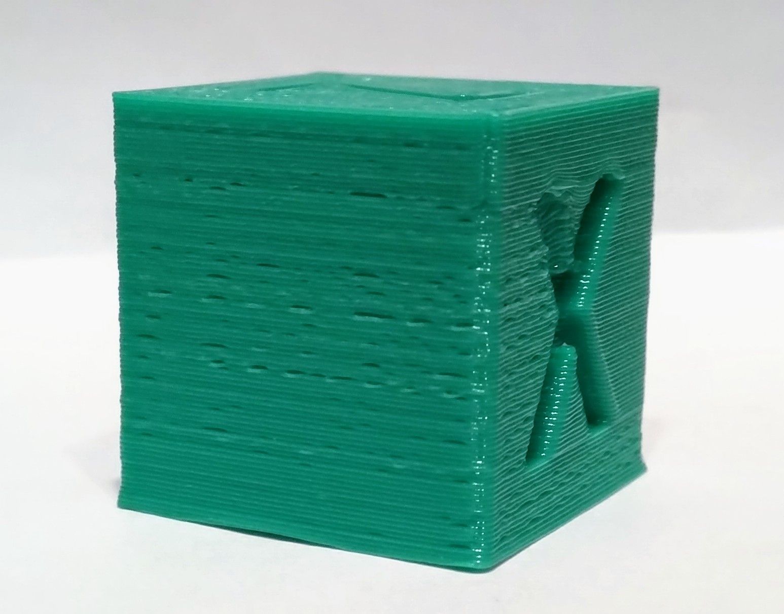
-
@skezo what does M122 say? Are the hiccups gone?
The values were wrong, so you should leave the new values, even if the holes are still there.
You say the holes are at the same location. One possibility for test would be to rotate the object and reprint (+ maybe print at different print bed location). If the holes are still at the same location, it is a problem with the STL object. If they are at different locations then, it is a printer or configuration problem.
Rotation would mean the labels XYZ are not correct any more, you should mark the print object with the correct directions after the print.The holes can come from underextrusion, you should check the extrusion parameter (the test to print 100 mm eg and verify your M92 E setting).
-
Under extrusion seems likely. Possibly unstable hotend temps.
PID tune the hotend and bed heaters, re calibrate the extruder.
-
@JoergS5 @Phaedrux
Hiccups seem to be gone now. RanM122every few mins during the print. Each time the following was returned:Hiccups: 0(0).I re-calibrated the extruder (updated
M92 E118.68).I re-ran PID tune for the hotend.
I then rotated the STL file and re-printed it (see below). The gaps seem to be in the exact same place as the non rotated prints.
-
@skezo I am not a specialist to handle filament (PETG) problems and cannot help further. But there are many users here who have a lot of experience.
To get the attraction of PETG specialist, you could rename the title of this thread to include PETG. The title has a display problem with the and symbol anyway.
-
I think your retraction speed is way too high, try 70mm/s.
-
-
try few other slicers and compare results
-
-
@skezo Is it only happen with PETG? Could be it has too much moisture in it?
-
Are you running the part cooling fan too high for PETG?
Do you have different filament to test with?
Even though you've tuned the extruder can you also try increasing the extrusion factor to see if the gaps are reduced?
-
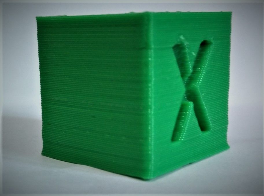
Setting the extrusion factor to 0.95 or above removes the gaps but when I run the extrusion multiplier calibration that value I get is 0.86 (this prints the walls at the correct width but has under extrusion). How can I balance extrusion with accuracy?
-
Filling the proper extrusion volume is a combination of the amount of plastic coming out of the nozzle and the distance from the nozzle to the surface being printed on. If the Z axis steps per mm is slightly off you could have a greater gap than expected leading to the appearance of underextrusion.
@skezo said in Trying to remove tiny holes/gaps on layers...:
but when I run the extrusion multiplier calibration
How exactly are you doing that?
-
If I set the extrusion multiplier to 0.86 I can see the nozzle laying beads of filament on some layers (see below image). Which is what I think is causing the gaps in the calibration cube.
For extrusion multiplier calibration I have been printing 40mm cube in vase mode and 40 mm cube with a single vertical perimeter. Then measuring the wall thickness with calipers.
Extrusion multiplier = Old Extrusion Multiplier * (Expected Thickness/Measured Thickness)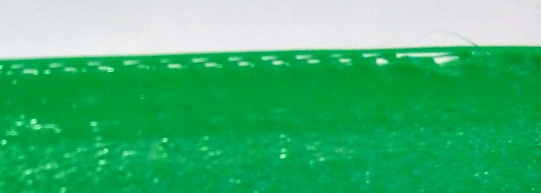
-
Perhaps give this calibration method a try.
https://duet3d.dozuki.com/Guide/Ender+3+Pro+and+Duet+Maestro+Guide+Part+4:+Calibration/40
What is the filament path like? Does the filament feed smoothly or is there friction and resistance?