How to measure leadsrew coordinates
-
I'm running into 5 iterations every time. Just recognized that one of my leadscrews often gets stuck when moving the bed. Need to find out the reason for that.
Phew....my build seems to ba a never ending story.
-
OK, at least I fixed my Z leadscrew issue.
The first problem I have is, that at the first iteration of probing the bed near the left two leadscrews, the hotend is moving over the defined X/Y max limit and crashes into the end of the rails. Maybe I'm blind but cannot find the misconfiguration.
Here's my complete config:
config.g
; General preferences G90 ; send absolute coordinates... M83 ; ...but relative extruder moves M550 P"duet3" ; set printer name M669 K1 ; select CoreXY mode ; Drives ; X:0.0, Y:0.1, E:0.2, Z_left_rear:0.3, Z_left_front:0.4, Z_right:0.5 M569 P0.0 S0 ; physical drive 0.0 goes forwards M569 P0.1 S0 ; physical drive 0.1 goes forwards M569 P0.2 S0 ; physical drive 0.2 goes forwards M569 P0.3 S0 ; physical drive 0.3 goes forwards M569 P0.4 S1 ; physical drive 0.4 goes forwards M569 P0.5 S1 ; physical drive 0.5 goes forwards M584 X0.0 Y0.1 Z0.3:0.4:0.5 E0.2 ; set drive mapping M350 X16 Y16 Z16 E16 I1 ; configure microstepping with interpolation M92 X200.00 Y200.00 Z400.00 E405.18 ; set steps per mm M566 X600.00 Y600.00 Z24.00 E120.00 ; set maximum instantaneous speed changes (mm/min) M203 X18000.00 Y18000.00 Z6000.00 E1200.00 ; set maximum speeds (mm/min) M201 X3000.00 Y3000.00 Z100.00 E5000.00 ; set accelerations (mm/s^2) M906 X1600 Y1600 Z1600 E1600 I30 ; set motor currents (mA) and motor idle factor in per cent M84 S30 ; Set idle timeout ; Three axis setup - leadscrew positions M671 X11:11:426 Y355:51:205 S20 ; Set up three Z-axis location ; Axis Limits M208 X28 Y24 Z0 S1 ; set axis minima M208 X355 Y355 Z400 S0 ; set axis maxima ; Endstops M574 X1 S1 P"io3.in" ; configure active-high endstop for low end on X via pin io3.in M574 Y1 S1 P"io4.in" ; configure active-high endstop for high end on Y via pin io4.in ; Z-Probe M950 S0 C"io7.out" ; create servo pin 0 for BLTouch M558 P9 C"^io7.in" H20 F1000 T6000 ; set Z probe type to bltouch and the dive height + speeds G31 P500 X36.47 Y-4 Z1.72 ; set Z probe trigger value, offset and trigger height M557 X50:300 Y80:355 S50 ; define mesh grid ; Heaters M308 S0 P"temp1" Y"thermistor" T95000 B3950 ; configure sensor 0 as thermistor on pin temp1 M950 H0 C"out2" T0 ; create bed heater output on out1 and map it to sensor 0 M307 H0 B0 S1.00 ; disable bang-bang mode for the bed heater and set PWM limit M140 H0 ; map heated bed to heater 0 M143 H0 S120 ; set temperature limit for heater 0 to 120C M308 S1 P"temp0" Y"thermistor" T500000 B4723 C1.19622e-7 ; configure sensor 1 as thermistor on pin temp0 M950 H1 C"out3" T1 ; create nozzle heater output on out2 and map it to sensor 1 M307 H1 B0 S1.00 ; disable bang-bang mode for heater and set PWM limit ; Fans M950 F0 C"out4" Q500 ; create fan 0 on pin out4 and set its frequency M106 P0 S0 H-1 ; set fan 0 value. Thermostatic control is turned off M950 F1 C"out5" Q500 ; create fan 1 on pin out5 and set its frequency M106 P1 S1 H-1 ; set fan 1 value. Thermostatic control is turned on M950 F2 C"out6" Q500 ; create fan 2 on pin out6 and set its frequency M106 P2 S0.3 H-1 ; set fan 2 value. Thermostatic control is turned off M950 F3 C"out7" Q500 ; create fan 3 on pin out7 and set its frequency M106 P3 S1 H-1 ; set fan 3 value. Thermostatic control is turned off ; Tools M563 P0 S"Hotend" D0 H1 F0 ; define tool 0 G10 P0 X13 Y20 Z0 ; set tool 0 axis offsets G10 P0 R0 S0 ; set initial tool 0 active and standby temperatures to 0C ; Custom settings are not defined ; Miscellaneous M575 P1 S1 B115200 ; enable support for PanelDue M501 ; load saved parameters from non-volatile memory T0 ; select first tool bed.g
if !move.axes[0].homed || !move.axes[1].homed ; If the printer hasn't been homed, home it M98 P"0:/sys/homeall.g" ; home y and x M98 P"0:/sys/homez.g" ; home z M561 ; clear any bed transform ;M558 P9 H5 F120 T24000 ; increase dive height M98 P"bed_threeScrews.g" ; perform bed tramming echo "Bed Traming Cycle: 1 - Difference was " ^ move.calibration.initial.deviation ^ "mm" while move.calibration.initial.deviation >= 0.01 ; perform additional tramming if previous deviation was over 0.01mm if iterations = 5 abort "Too many auto tramming attempts" M98 P"bed_threeScrews.g" ; perform bed tramming echo "Bed Traming Cycle: " ^ iterations + 2 ^ " - Difference was " ^ move.calibration.initial.deviation ^ "mm" continue G28 Z ; home z bed_threeScrews.g
G30 P0 X41 Y355 Z-99999 ; probe near leadscrew one G30 P1 X41 Y55 Z-99999 ; probe near leadscrew two G30 P2 X338 Y205 Z-99999 S3 ; probe near leadscrew three -
G30 takes into account the probe offset. So you need to take that into account.
If you're going to 355 for example, that will be offset a further 4mm to take your y-4 into account -
Got it, thanks!
So now all three points will be probed:
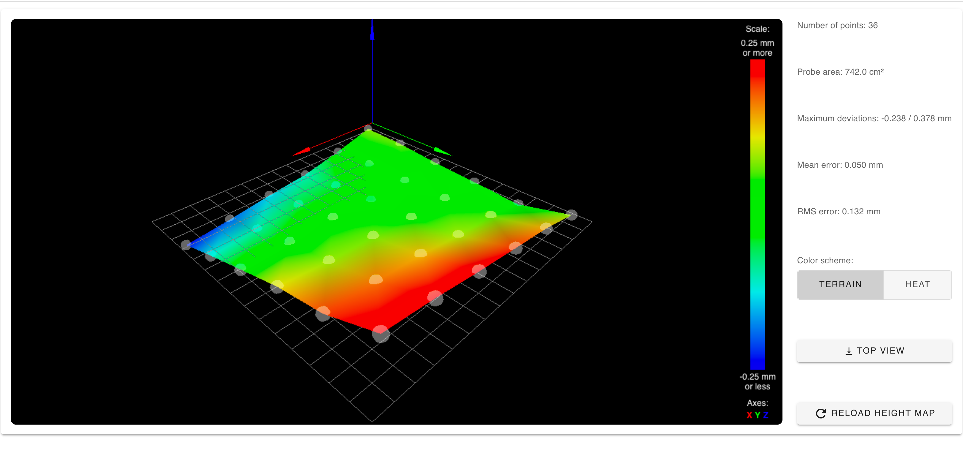
9/18/2020, 11:00:53 AM Bed Traming Cycle: 1 - Difference was 0.004mm 9/18/2020, 11:00:53 AM Leadscrew adjustments made: 0.163 0.171 0.158, points used 3, (mean, deviation) before (0.164, 0.004) after (0.000, 0.000) but when I do a G29 afterwards, the heightmap looks like

I'm wondering if I assembled the three bed holder at the right positions. Currently it looks like this:

Left Front:
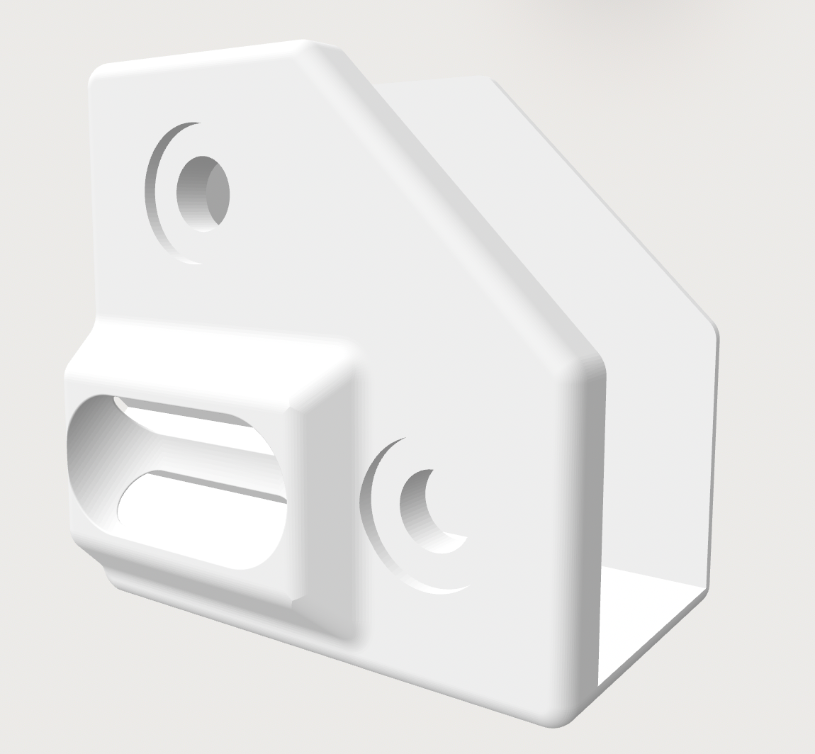
Left rear:

BTW: this is not the final bed setup. Just reused some old parts to check if that all works out
")
-
You have an apparent twist in your height map. Typical causes of this:
- If it's a CoreXY printer, check that the gentry is flat and not twisted. My E3D tool changer suffers from this if I don't put padding under one of the feet.
- If the print carriage rotates about the X axis as it moves along it, this rotation will change the distance between the nozzle and the bed. If the X axis uses two parallel linear rods, check that there is no relative twist between them.
- Or of course the bed could be twisted.
-
Gantry and bed are not twisted.
I just levelled the bed with a digital leveler and ran a G32. Although the bed should be in level it was set down on the right side, where the roll screw is located.
-
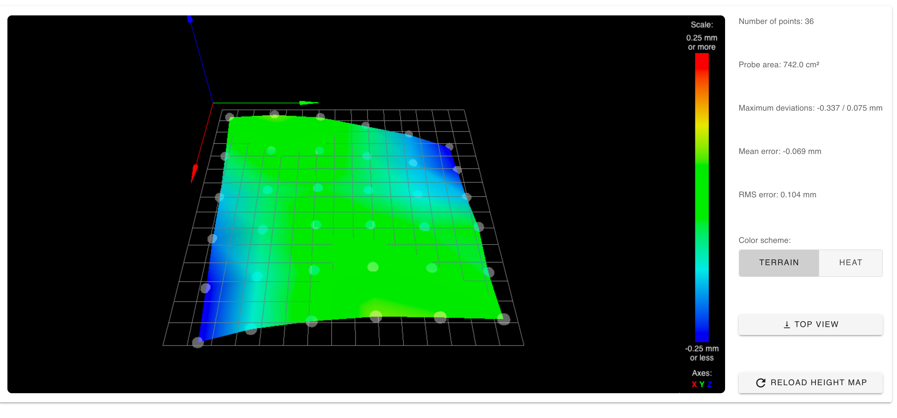
Found out, that I forgot to change the steps after changing the Z axes to SFU1204. At least it looks a little bit better now.
9/18/2020, 1:33:08 PM Bed Traming Cycle: 1 - Difference was 0.010mm 9/18/2020, 1:33:08 PM Leadscrew adjustments made: 0.068 0.043 0.066, points used 3, (mean, deviation) before (0.059, 0.010) after (-0.000, 0.000) 
Any other ideas?
-
@MartinNYHC check how level your two guide rails are for the Y axis. Check both along their lengths individually and for any height difference between them.
From you height map, it looks like the three points you probed for the auto tramming are all at the same height, give or take. This means that it has correctly levelled the bed based on these three points. I'm assuming here that the 0,0 point is at the front left in the photo of your bed (where I'd expect it).
Looking at the heightmap, it seems that your y-rail on the right hand side (at your x-max side) is not flat compared to the left hand one, leading to the twist you are seeing in your height map.
-
@engikeneer Just measured and the front end of the right extrusion is 1mm higher. How the hell shall one assemble the frame that it is 100% square?

-
@MartinNYHC build it on a surface plate.
 I’m actually lobbying for our maker space to get one so I can use it for my next build...
For my BLV I printed off two copies of the jigs and used those to hold both sides simultaneously. Still don’t have it up and running again though!
-
@MartinNYHC if you find an answer to that, please let me know! I don't have a digital level gauge so just kept adjusting mine, redoing the mesh, then repeating until I gave up

One other thought. You can probe more than three points if you like and anywhere on the bed. It will then do least squares to get the average bed plane and auto tram to that (thats why it gives a std dev before adjustments). Might be worth considering when you've done what you can with mechanicals to minimise the bed mesh?
-
@engikeneer Yes, I already added some additional probing points. Will try it out tomorrow.
-
Since I don't want to reassemble the frame once again before I'm sure what exactly the problem is, I just placed a washer between the bed frame and the bed holder on the right side. Looks better...