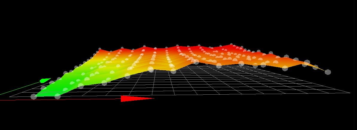
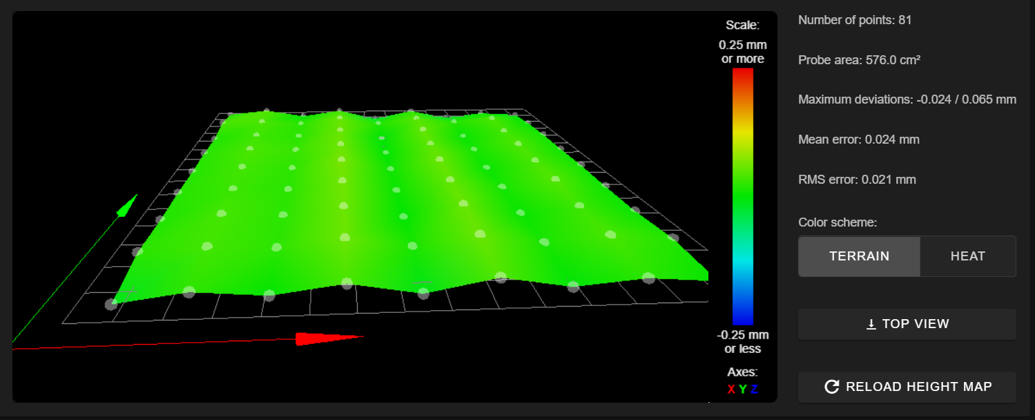
Triangular wave and print area
-
The motors are Quimat Nema 17 Stepper Motor 1.7 A 0.59 Nm 84 oz.in 47mm
-
@Leblond said in Triangular wave and print area:
1.7 A
so running them at 75% rounding to nearest 100 is 1300.
-
ok I took them to 1.3 and I'm doing the test again later
-
25/10/2020, 20:56:11 G32 bed probe heights: 0.198 0.195 0.195 0.198 0.195 0.200 0.195 0.200 0.192 0.195, mean 0.196, deviation from mean 0.002
25/10/2020, 20:55:37 G32 bed probe heights: 0.183 0.180 0.180 0.183 0.183 0.183 0.183 0.180 0.180 0.183, mean 0.181, deviation from mean 0.001
25/10/2020, 20:55:04 G32 bed probe heights: 0.183 0.178 0.173 0.170 0.178 0.173 0.173 0.178 0.178 0.173, mean 0.175, deviation from mean 0.004
25/10/2020, 20:54:31 M98 P"0:/macros/Calibrazione a punto singolo/Calibrazione x 10"
G32 bed probe heights: 0.195 0.192 0.192 0.195 0.192 0.195 0.195 0.195 0.188 0.195, mean 0.194, deviation from mean 0.002 -
I'm retrying cold-meshing the plate to see if we've made any improvements
-

-
no improvement
-
it seems to be very consistent.
can you turn the glass 90 degrees?
-
Is the X carriage on wheels?
I'm not familiar with the printer and can't tell from the photos I've seen,
Almost looks like an eccentric wheel causing the nozzle to rise & fall with each rotation -


-
Yes, the trolley is on rails and has eccentrics
-

I've had the same problem once , it was the x axis wheels and stopped the ripple with linear rails , but I guess getting better would have fixed it too.
-
@Veti yes I have already tried to rotate it 90 degrees, but no improvement
-
@peter247 in practice they had?
-
@Leblond said in Triangular wave and print area:
Yes, the trolley is on rails and has eccentrics
I don't think he's talking about eccentric nuts to adjust wheel tension, I think he means the wheel itself may be out of round.
Is the spacing between the peaks equivalent to a full rotation of the wheel?
-
@Phaedrux ok, but I tried to move it manually without the belt to see if it was free and so it was, do you think the bearings need to be changed?
-
Well the real question is does mesh compensation work to produce a good first layer?
Do a test print once with mesh enabled and another with it disabled. You should be able to tell if the mesh is accurate or not.
-
@Phaedrux ok I will try in the meantime I disassembled the x axis turned the bearings
"just to give it a try while I was waiting for some advice from you" and now I've reassembled it and put it back to making a cold mesh to see if anything has changed, then I'll try to print to see if the mesh works or not, tomorrow I will post the results with and without mesh, for the moment thanks @Phaedrux. -
@Phaedrux looking at the graphic mesh and checking the coordinates of X which are spaced by 20mm, in 60mm the wheel should make a full turn, I did a free test: I lowered the probe stem I raised the Z axis until it touches the flat, at this point I moved the X axis by 60mm and about 30mm it raised and then lowered in the remaining 30mm, you know you were right the bearings are gone
-
have you decided what to do about it?
new bearings or linear rail conversion?