Duet3D Logo Duet3D
    • Tags
    • Documentation
    • Order
    • Register
    • Login

    Need help! G29 mesh bed compensation over compensation

    Scheduled Pinned Locked Moved
    Tuning and tweaking
    7
    33
    1.5k
    Loading More Posts
    • Oldest to Newest
    • Newest to Oldest
    • Most Votes
    Reply
    • Reply as topic
    Log in to reply
    This topic has been deleted. Only users with topic management privileges can see it.
    • Jaysonundefined
      Jayson
      last edited by

      I'm New the the duet world and I'm building a corexy machine with a 500x500 bed.

      I can't get a good first layer. I run G28 and home with the z probe in the center of the bed. Then I run the G29 command and it starts printing.

      The parts of the bed that are low it really grinds the filament into almost touching the nozzle to the build platform. Then the parts that are high it doesn't stick at all and lifts z way too high.

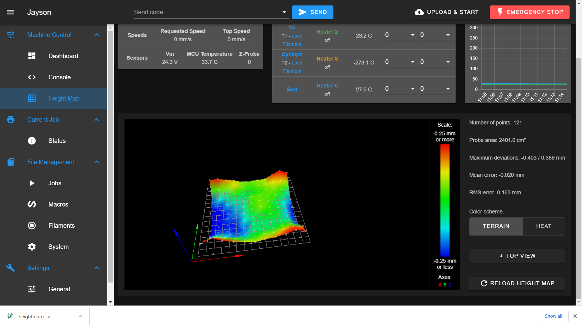
      I have probed the bed multiple times in a row with 121 points and the mesh on the web interface is vary consistent and the first layer has the same issues in the same areas every time

      I'm running the latest firmware.

      1 Reply Last reply Reply Quote 0
      • PCRundefined
        PCR
        last edited by

        Please Post your config.g and a Sample gcode aswell as the heighmap.csv

        1 Reply Last reply Reply Quote 0
        • Jaysonundefined
          Jayson
          last edited by

          config.g
          heightmap.csv

          1 Reply Last reply Reply Quote 0
          • Jaysonundefined
            Jayson
            last edited by

            my bed is warped and I have plans to fix it but g29 shouldnt have any trouble compensating that.

            here is the start of the gcode i was using. it came from the teaching tech websight.

            ; G-Code originally generated by Simplify3D(R) Version 4.1.2, based on proposed code by vector76
            ;M80 ; power supply on
            G90
            M82
            M106 S0
            M140 S60 ; custom bed temp
            M190 S60 ; custom bed temp
            M104 S200 T1 ; custom hot end temp
            M109 S200 T1 ; custom hot end temp
            G28 ; home all axes
            G29 ; probe ABL
            ;M420 S1 ; restore ABL mesh
            ; custom start gcode
            ; process Color1
            ; layer 1, Z = 0.200
            ;T1
            G92 E0.0000
            G1 E-1 F2400 ; custom retraction

            1 Reply Last reply Reply Quote 0
            • PCRundefined
              PCR
              last edited by

              What Kind of probe are you using?

              The negative value in the G31 looks strange.

              Have you done the offset calibration?

              https://duet3d.dozuki.com/Wiki/Test_and_calibrate_the_Z_probe#Section_Calibrate_the_Z_probe_trigger_height

              The Offset is different than for marlin.

              Jaysonundefined 1 Reply Last reply Reply Quote 0
              • Jaysonundefined
                Jayson @PCR
                last edited by

                @PCR I did an offset calibration.
                My printer is tool changing so I mounted a simple micro switch to my carriage.
                When I pick a tool the nozzle hangs down about 4mm below the trigger hight.
                So it's a negative value of around 4mm

                Vetiundefined 1 Reply Last reply Reply Quote 0
                • PCRundefined
                  PCR
                  last edited by

                  Ah ok then this make Sense!

                  1 Reply Last reply Reply Quote 0
                  • Vetiundefined
                    Veti @Jayson
                    last edited by

                    @Jayson

                    M350 X256 Y256 Z128 I0 ; configure microstepping without interpolation

                    this will overload the cpu. unless there is a specific reason, you should go with x16 and interpolation.

                    G31 P500 X0 Y50 Z-4.09 ; set Z probe trigger value, offset and trigger height

                    as jason said, negative values this big would bean the nozzle goes 4mm into the bed before the probe activates

                    also make sure what the offset is correct. is you probe really 50mm behind the nozzle?

                    M558 P5 C"^zprobe.in" H2 F900 T24000 ; set Z probe type to switch and the dive height + speeds

                    P8 is preferred to P5 unless you really need the filtering

                    Jaysonundefined 1 Reply Last reply Reply Quote 0
                    • Jaysonundefined
                      Jayson @Veti
                      last edited by

                      @Veti you lost me at interpolation....
                      I would really appreciate it if you could type out the replacement command for M350 X256 Y256 Z128 I0. Then I can just copy, paste and call you a genius 😁

                      I can handle switching P5 and P8.

                      And yes my probe it really 50mm behind and 4.09mm above my nozzle. I just have to make sure that no tool is mounted when I probe.

                      Vetiundefined 1 Reply Last reply Reply Quote 0
                      • Vetiundefined
                        Veti @Jayson
                        last edited by

                        @Jayson said in Need help! G29 mesh bed compensation over compensation:

                        And yes my probe it really 50mm behind and 4.09mm above my nozzle. I just have to make sure that no tool is mounted when I probe.

                        can you post a picture of the assembly?

                        change the steps like this

                        M350 X16 Y16 Z16 I1 ; configure microstepping without interpolation
                        M92 X80 Y80 Z900 E420.00:1888.21:420.00:420.00 ; set steps per mm

                        However. when converting the numbers back i realized the Z900 is very strange.
                        What kind of z setup do you have?
                        Common values are 400 (most printers tr8x8)
                        800 (sfu1204)
                        1600 (tr8x2)

                        Jaysonundefined 1 Reply Last reply Reply Quote 0
                        • Jaysonundefined
                          Jayson @Veti
                          last edited by

                          @Veti I implemented your changes and it solved a few problems. Something was holding back my top speeds and I guess it was an over loaded cpu.

                          Trying a test print now.

                          The few extra z steps are from a slight gear reduction by a belt from my z stepper to my lead screws

                          Thanks a lot for the help. I will post again when the test print is completed

                          1 Reply Last reply Reply Quote 0
                          • Jaysonundefined
                            Jayson
                            last edited by

                            IMG_20201113_093229.jpg IMG_20201113_091147.jpg

                            here is a picture of what I'm going to refer to as my chuck, without a tool and ready for probing.

                            the second picture is with a custom machined water cooled cold end with a v6 and zesty nimble. (still vary much a work in progress)

                            1 Reply Last reply Reply Quote 0
                            • Jaysonundefined
                              Jayson
                              last edited by

                              still having the problem.... 😢

                              this picture is from my most recent test.
                              as you can see two are too close and three are too far.IMG_20201113_101604.jpg

                              1 Reply Last reply Reply Quote 0
                              • gloomyandyundefined
                                gloomyandy
                                last edited by

                                Are those the actual locations where the cubes were printed or did you move them?

                                1 Reply Last reply Reply Quote 0
                                • Vetiundefined
                                  Veti
                                  last edited by

                                  post a picture of your heightmap

                                  1 Reply Last reply Reply Quote 0
                                  • Jaysonundefined
                                    Jayson
                                    last edited by

                                    I kept the same orientation, just moved them in close for the picture

                                    1 Reply Last reply Reply Quote 0
                                    • Jaysonundefined
                                      Jayson
                                      last edited by

                                      I have tried the print with the heat bed off at room temperature to eliminate thermal expansion but still the same result.

                                      I have also shimmed the low side of the bet up 3 mm to drastically alter the bed mesh and the prints come out looking the exact same.

                                      1 Reply Last reply Reply Quote 0
                                      • Jaysonundefined
                                        Jayson
                                        last edited by

                                        Screenshot (1).png

                                        it is a 500x500 bed with a silicone heater and buildtak flex plate.
                                        it has a 1/4" T6 6061 aluminum plate that I sheared from a piece of scrap at work. It defiantly has some warp that I am working to physically straighten now.

                                        Vetiundefined 1 Reply Last reply Reply Quote 0
                                        • Vetiundefined
                                          Veti @Jayson
                                          last edited by Veti

                                          @Jayson said in Need help! G29 mesh bed compensation over compensation:

                                          it has a 1/4" T6 6061 aluminum plate that I sheared from a piece of scrap at work.

                                          that is not thick enough for a 500x500 build plate. as you can see from the sagging heightmap.
                                          see this recent discussion
                                          https://forum.duet3d.com/topic/19398/height-map-500mmx500mmx4mm-aluminium-build-plate

                                          your testprint is not even good in the center. so you have not dialed in the z trigger height well enouch.
                                          adjust with babystepping while printing until you get a good first layer, then adjust the offset with the babystep value.

                                          also measure the z probe trigger heigh in each of the corners.
                                          i would assume for your build they are different.
                                          this can be due different factors.
                                          one possibility for your printer with such a large print area is sagging axis due to its own weight, which introduces rotation of the carriage. this causes varying probing offset.

                                          one way to compensate for that is use a probe that uses the nozzle like a precision piezo

                                          jay_s_ukundefined Jaysonundefined 3 Replies Last reply Reply Quote 0
                                          • jay_s_ukundefined
                                            jay_s_uk @Veti
                                            last edited by

                                            I would suggest moving your z probe to be X0, Y0 and Z0.
                                            From there, you can set the tool offsets using G10.
                                            It makes working everything out so much easier.
                                            You can than use TAMV to calculate the X and Y offsets of each tool in relation to the z probe.
                                            That's how I have my toolchanger set up.

                                            Owns various duet boards and is the main wiki maintainer for the Teamgloomy LPC/STM32 port of RRF. Assume I'm running whatever the latest beta/stable build is

                                            Jaysonundefined 1 Reply Last reply Reply Quote 0
                                            • First post
                                              Last post
                                            Unless otherwise noted, all forum content is licensed under CC-BY-SA