Duet3 -> SBC wiring (without the ribbon cable)
-
we mainly wire up the SBC on the LPC/STM port stuff.
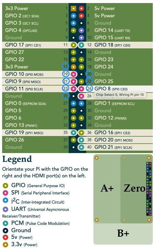
All the correct pins on the pi are detailed here
https://github.com/gloomyandy/RepRapFirmware/wiki/SKR-SBCpretty picture
-
@jay_s_uk said in Duet3 -> SBC wiring (without the ribbon cable):
we mainly wire up the SBC on the LPC/STM port stuff.
All the correct pins on the pi are detailed here
https://github.com/gloomyandy/RepRapFirmware/wiki/SKR-SBCThat's interesting: You use pin 6 for GND instead of pin 20. Is there a particular reason? (My reasoning for using pin 20 was so that it'd be clustered with the other 5 required pins, allowing the use of two 1x3 or one 2x3 housing(s.)
"I'm not saying that you are wrong - I'm just trying to fit it into my real world simulated experience."
-
@garyd9 no reason at all.
I should probably change it to 20. They all do the same thing. -
I'm kind of curious: what kind of board is that diagram wiring to? If resistors are needed on the signal lines, I'm guessing it's not electrically identical to a duet3 board...
"I'm not saying that you are wrong - I'm just trying to fit it into my real world simulated experience."
-
@garyd9 said in Duet3 -> SBC wiring (without the ribbon cable):
I'm kind of curious: what kind of board is that diagram wiring to?
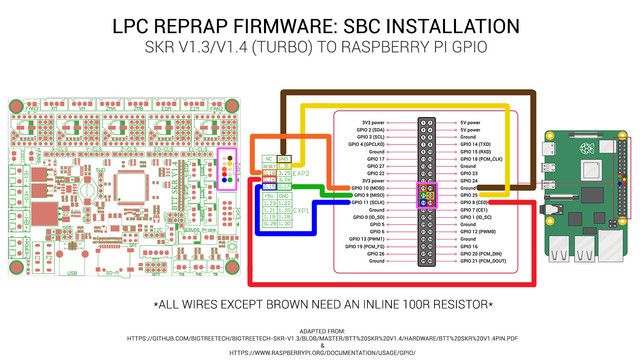
BigTreeTech SKR V1.3
-
@garyd9 yep, an SKR 1.3. It was just the quickest thing I had to hand that showed the pi pins.
We have resistors on the SPI lines as on the duet they're built in whereas they aren't for us. Just adds a bit more protection. -
@garyd9 said in Duet3 -> SBC wiring (without the ribbon cable):
That's interesting: You use pin 6 for GND instead of pin 20. Is there a particular reason? (My reasoning for using pin 20 was so that it'd be clustered with the other 5 required pins, allowing the use of two 1x3 or one 2x3 housing(s.)
which pin used for ground shouldn't matter, I used pin 20 along with the 5 signal lines and pin 6 & 9 along with the 5V for power. (i guess in theory more ground lines are more better from a signal integrity point of view but never had any issues with the SPI speed used at the time)
-
@bearer said in Duet3 -> SBC wiring (without the ribbon cable):
which pin used for ground shouldn't matter, I used pin 20 along with the 5 signal lines and pin 6 & 9 along with the 5V for power. (i guess in theory more ground lines are more better from a signal integrity point of view but never had any issues with the SPI speed used at the time)
Maybe I'm just unlucky but tried to use my own cable a number of times and got random disconnections between SBC and Duet.
Have tried incorporating two ground connections instead of just pin 20 and also made a lead a short as possible.
The reason for using my own cable was that I needed some free gpio pins on the pi.
Back on the ribbon cable now without any problems and got access to the gpio pins by cutting back the appropriate cables on the ribbon. -
I suggest using at least two ground wires, the two closest to the SPI signals. Run all the wires close together. Duets need the 3.3V connection too, except for MB6HC version 0.6.
Duet WiFi hardware designer and firmware engineer
Please do not ask me for Duet support via PM or email, use the forum
http://www.escher3d.com, https://miscsolutions.wordpress.com -
@dc42 said in Duet3 -> SBC wiring (without the ribbon cable):
I suggest using at least two ground wires, the two closest to the SPI signals. Run all the wires close together. Duets need the 3.3V connection too, except for MB6HC version 0.6.
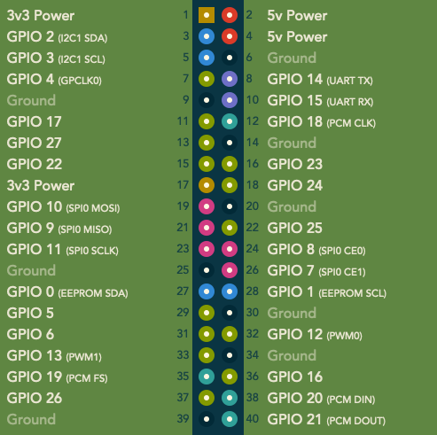
So pin1 (and/or pin 17?) also needs a connection for v1.0.x DHC boards? Can I suggest that the image shown on the wiki (https://duet3d.dozuki.com/Wiki/Duet_3_Mainboard_6HC_Wiring_Diagram) updated to include that pin in the "SBC 26 Pin Header" list?
-
@garyd9 Thanks for pointing that out, I have updated the diagram.
-
@T3P3Tony said in Duet3 -> SBC wiring (without the ribbon cable):
@garyd9 Thanks for pointing that out, I have updated the diagram.
Thank you. Thank you also for clarifying in the diagram that it's pin 17 (not pin 1) that needs the connection.
That suggests that I can run a 5x2 covering pins 17-26 on a (much) smaller ribbon cable which would cover all the SPI related pins, 3.3vdc on 17, and the GND's on 20 and 25.
It just so happens that I have a few 300mm 5x2 ribbon cables that I purchased for a duet/wifi to paneldue connection (that I later changed to a simple 4 wire connection.) I'll have to give one of them a try for a duet3/SBC connection and see what happens. (I'm not assuming success due to it being 300mm, but duet3d stuff tends to be over-engineered, so it might work fine.)
Again - thank you!
-
Could somebody confirm the latest pin outs for the sbc ribbon connects on a Mini 5 and Pi4B please?
-
-
@Phaedrux got it thanks
")
-
@carcamerarig For Raspberry Pi pinout, see https://pinout.xyz/#
For Duet 3 Mini 5+ pinout, see https://duet3d.dozuki.com/Wiki/Duet_3_Mini_5plus_WiringBasically, the Duet SBC port is the same pinout as the Raspberry Pi, with the Duet replicating pins 1 to 26. The top of each header is pin 1 (on the top left) and pin 2 (top right).
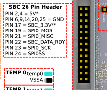
You need to connect, pin to pin, pins
17 (3.3V), 19 (SPIO MOSI), 20 (GND), 21 (SPIO MOSI), 22 (SBC_DATA_RDY), 23 (SPIO_SCK), 24 (SPIOSS) and 25 (GND).Ian
Bed-slinger - Mini5+ WiFi/1LC | RRP Fisher v1 - D2 WiFi | Polargraph - D2 WiFi | TronXY X5S - 6HC/Roto | CNC router - 6HC | Tractus3D T1250 - D2 Eth
-
5 x 2 Dupont block.
-
 undefined TRATOON referenced this topic