IDEX CoreXY, With Only 2 Motors.
-
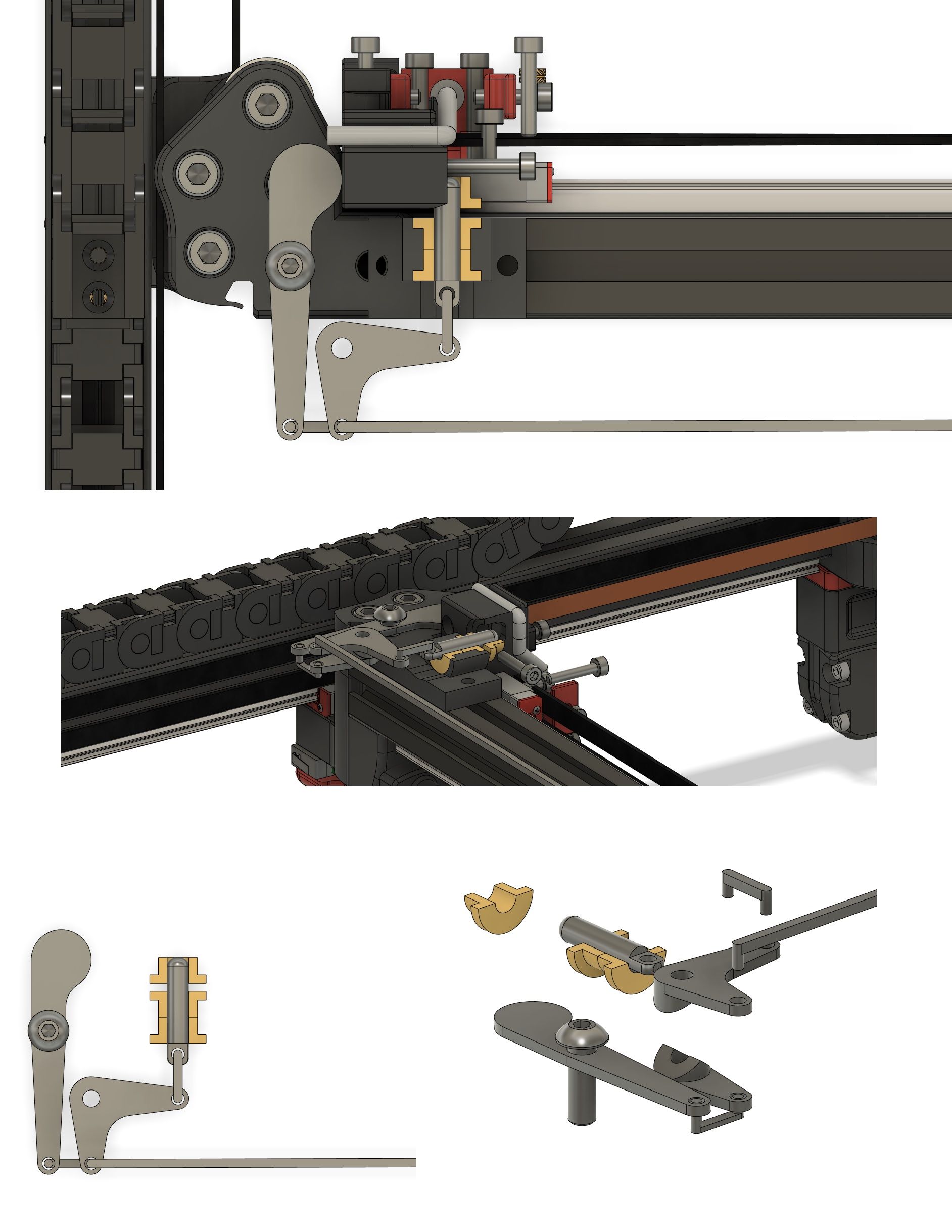
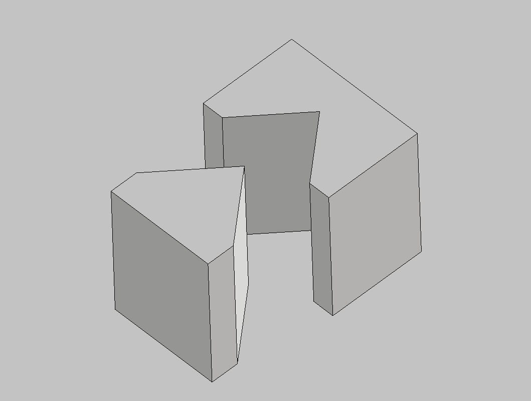
Alrighty, been a busy day, haven’t had much chance to ponder things, but here is my rough idea. It needs a lot more refinement and maybe it can be simplified further but hopefully this is good enough to portray the idea.
There is a brass bush in the carriage where a piece of linear rod can be inserted into to lock it in place.
The far left arm is actuated by the carriage moving to the park position. The secondary idler arm is similar to a servo saver, two seperate arms cut with a v groove allowing the lower arm that’s connected to the carriage actuator to rotate, while the upper arm connected to the locking pin stays in place until the lock pin meets the carriage hole, and snaps into place. A long connecting rod is attached to a mirrored assembly at the other end. Once the lock pin snaps into the parked carriage, it is released simultaneously at the other end.

-
@RichardDuke
If that would work, it had a great advantage over my idea. The beam wouldn't have to travel to the far end, but switch carriers where it is.
But there is one thing, I have doubts. A Servo Saver would store a certain amount of energy, before it can move the pin in the brass bush.
The energy would release, the very moment when the pin fits in the bushing. But at the same time, it tries to pull out the other pin from the bushing. This is only possible by twisting the other Servo Saver because the other side is still locked.
Assuming both Servo Savers have the same spring tension applied, where does the extra energy come from? In my mind, both Servo Savers would stop in the middle, where the forces are equal.
Another point is the push action of the long connecting rod. That's never a good idea, but can be modified to a pull action with a different arm-setup.I hope, I'm wrong. Let's find out by building a Proof_of_Concept thing.
Is there a way to avoid printing the Servo Saver V-grooves? -
@o_lampe ahh yes your right about the energy thing at both ends, it will be equal so it will probably bind up and freeze. But I think it can be altered to accomodate. It is a little bit of a complex system though, electric servos are sounding pretty good at the moment haha
Richard
-
Nice graphics!
Do you do that sort of work professionally?
Frederick
Printers: a E3D MS/TC setup and a RatRig Hybrid. Using Duet 3 hardware running 3.4.6
-
looks like solidworks to me
-
@RichardDuke said in IDEX CoreXY, With Only 2 Motors.:
@o_lampe ahh yes your right about the energy thing at both ends, it will be equal so it will probably bind up and freeze. But I think it can be altered to accomodate. It is a little bit of a complex system though, electric servos are sounding pretty good at the moment haha
My design also failed. Because it has to be symetric in both directions, it doesn't push the switch over the hump.
I watched some videos (for kids) Subject: How a ballpen works. Ran them in slowmotion to see every bit of it. There is a trick how to overcome our dilemma. But I don't see the light yet. Some kind of rotating excenter...a triangle if you will. Let me sleep over it, I have best ideas when I wake up.BTW: Did you know it took 66 engineers to invent the ballpen 1965?
-
A pin in a hole requires clearance, any slop is going to cause the active extruder to overtravel when changing direction which would give the same effect as ringing.
I would consider a tapered pin, or a wedge would be better. Then you don't have to worry about vertical alignment. However a tapered pin or wedge might require a spring because otherwise it would be hard on your servo.
-
@fcwilt said in IDEX CoreXY, With Only 2 Motors.:
Nice graphics!
I believe he is using Voron's stp files.
-
@fcwilt said in IDEX CoreXY, With Only 2 Motors.:
Nice graphics!
Do you do that sort of work professionally?
Frederick
These are the Voron .step files. Someone has put a lot of work into creating them with all the correct colours. I am just building on it in Fusion 360.
I guess you could call what I do a profession haha. I quit my job in the Automotive trade to pursue my 3D printing business from what started out as a hobby 7 years or so ago. I mostly focus on engineering related 3d printing, but the bulk of what I print is PLA investment casting patterns (I dont do the castings, just supply the patterns). Before you ask, yes we print a lot of cool sh!t that gets cast in metal, but I generally cant share most of it. But one of the coolest ones was this public sculpture, all of the spheres and the bendy straw collars were 3d printed and investment cast in bronze, the straight pipe is off the shelf. We went big straight out the gate as this was the first thing we ever investment cast with 3d printing.

Another cool one was this motorbike Cylinder head. Any my ugly mug holding the very intricate printed pattern.
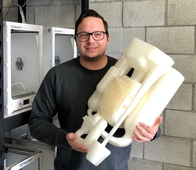
Richard
-
I've found a way to add a spring between locked carrier and the beams end.
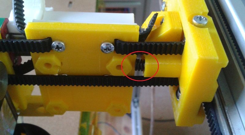
I made some ringing single-wall testprints with upto 90mm/s and acc. 2500mm/s^2, but there was no ringing or overshooting.
I saw other creepy stuff, but that's another thread. Just a little glimps...
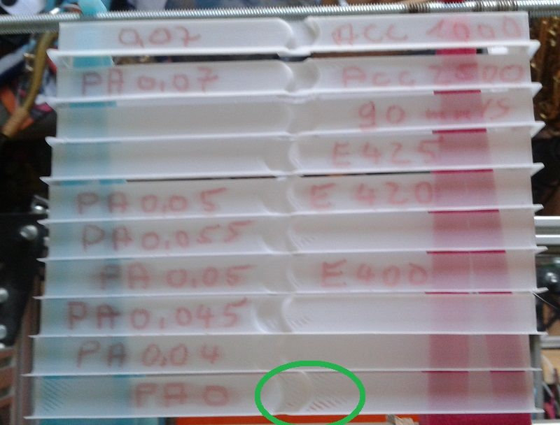
"PA" means pressure advance.
-
@RichardDuke
I dreamt about printing a mold to make silicone-rubber tracks for a garden truck, but now I want a radial engine-modell cast in aluminum. (Bronce is easier to cast?) -
I think, I'll put my brain on the real task and get the toolchanging to work.
For now I'll use a servo mounted on the far side to switch the locks. No added weight, and easy to implement.
I will also redesign the switches. No spring/ball but a piece of PTFE tube will execute both tasks. That will make the whole switch thinner. -
In another thread I found a link to @mrehorstdmd blog, where he used a digital dial indicator to check for unwanted axis-movement. I'll make a bracket to fit my analog dial to the locked (and springloaded) carrier to figure out how much more ringing I'll see with the spring vs. locked by a screw.
-
Here's a simple dual extrusion system to tilts the unused extruder away from the print:
https://hackaday.com/2021/03/07/this-dual-extrusion-system-rocks/ -
@mrehorstdmd
Hmm, the ramps used to tip over the extruders are clever!
Maybe in the next project. Or I might add a dual extruder to each carrier? 4 tools are better than 2! But then the printable area would be even smaller...
But first off all, I want to get to the ground with the possibilities of this hack. -
Q: Can I home my XU axis during tool changes (frequently)?
I have one side of the servo controlled lock-switches done and wanted to work on the toolchange macro.
Turns out, the springload of the carriers is hard to predict and the steppers pulling the carrier into the spring might loose steps.
It would be helpful, if I could use a homeX/homeU command with sensorless endstops to cope with lost steps during toolchange.
Is it possible to home axis' during toolchanges mid-print?
Especially, because of the frequently changing drive mapping, it could confuse the FW which driver reports lost steps for which endstop. -
@o_lampe said in IDEX CoreXY, With Only 2 Motors.:
Is it possible to home axis' during toolchanges mid-print?
Don't see why not. @mrehorstdmd did a test homing X and Y ever layer.
-
@Phaedrux said in IDEX CoreXY, With Only 2 Motors.:
Don't see why not.
@o_lampe said in IDEX CoreXY, With Only 2 Motors.:
it could confuse the FW which driver reports lost steps for which endstop
Because of the sensorless homing with varying stepper mappings?
-
I guess I don't follow the concern. Either because there isn't a real concern or I just don't understand it. I'm not sure which.
What would your gcode sequence look like? Script it out and maybe we can spot anything suspect.
-
@RichardDuke
hello, great achievement. do you have a site where we can download the stl?