Duet3D Logo Duet3D
    • Tags
    • Documentation
    • Order
    • Register
    • Login

    connecting a BLDC controller to duet2

    Scheduled Pinned Locked Moved
    Duet Hardware and wiring
    6
    21
    1.3k
    Loading More Posts
    • Oldest to Newest
    • Newest to Oldest
    • Most Votes
    Reply
    • Reply as topic
    Log in to reply
    This topic has been deleted. Only users with topic management privileges can see it.
    • tekstyleundefined
      tekstyle
      last edited by

      wondering how I am supposed to connect this to a fan output for PWM control on a Duet2wifi + duex5

      alt text

      so here is what I plan on doing.
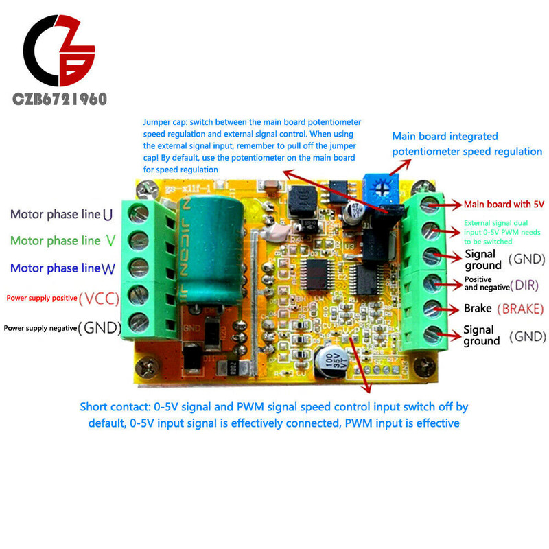
      Connect the GND on the controller to main GND on the board.
      Connect the VCC on the controller to the 24V PSU (this thing runs on 9-60V).

      put JUMPER across the "JUMPER INT 5V EN pins".
      connect the EXTERNAL SIGNAL INPUT (PWM) on the controller to the FANx (+) pin.
      connect the signal GND on the controller to the FANx(-) pin.
      connect the main board 5Vinput on the controller to a 24-5V step down voltage regulator that can supply the required Amperage (30mA). or perhaps an always on FAN input on the duet2

      I have a Duex5 and I have 24V fans that I run with my hotend thermostatically. Do I just keep the JUMPER on the VIN on the "V Fan jumper select"?

      alankilianundefined dc42undefined o_lampeundefined 3 Replies Last reply Reply Quote 0
      • alankilianundefined
        alankilian @tekstyle
        last edited by

        @tekstyle

        I would connect signal ground on the BLDC board to the Duet ground.

        Then, connect a 4.7 K Ohm resistor from FAN- to FAN+ and connect FAN- to the PWM input on the BLDC board. This should produce a signal on FAN- that goes from 0 Volts to whatever you have your fans set to. Which should be set to 5 Volts.

        I would also just connect the BLDC 5 Volt input to a 5 Volt output on the Duet, but of course you need to make sure the current required by the BLDC board is not more than the current available on the Duet 5 Volt signal.

        What are you trying to do with this?

        SeemeCNC Rostock Max V3 converted to V3.2 with a Duet2 Ethernet Firmware 3.2 and SE300

        tekstyleundefined 1 Reply Last reply Reply Quote 0
        • dc42undefined
          dc42 administrators @tekstyle
          last edited by dc42

          @tekstyle it would be simpler to connect ground, +5V and INPUT to one of the five PWM outputs of the DueX. I am assuming that you are not using all five heater outputs on the DueX, because the PWM outputs share control signals with those heaters.

          Duet WiFi hardware designer and firmware engineer
          Please do not ask me for Duet support via PM or email, use the forum
          http://www.escher3d.com, https://miscsolutions.wordpress.com

          tekstyleundefined 1 Reply Last reply Reply Quote 0
          • o_lampeundefined
            o_lampe @tekstyle
            last edited by

            @tekstyle
            Does it really need a negative voltage on the DIR pin? I always get nervous, reading those chinglish descriptions. Especially when my expensive Duet board is at risk.
            Cant you try it with a cheaper Arduino board first?

            1 Reply Last reply Reply Quote 0
            • dc42undefined
              dc42 administrators
              last edited by

              @o_lampe said in connecting a BLDC controller to duet2:

              Does it really need a negative voltage on the DIR pin?

              I don't think so, I think it means positive and negative motor direction.

              Duet WiFi hardware designer and firmware engineer
              Please do not ask me for Duet support via PM or email, use the forum
              http://www.escher3d.com, https://miscsolutions.wordpress.com

              o_lampeundefined 1 Reply Last reply Reply Quote 0
              • o_lampeundefined
                o_lampe @dc42
                last edited by

                @dc42
                I agree, but there is also the confusing description of the onboard solder bridge....

                1 Reply Last reply Reply Quote 0
                • tekstyleundefined
                  tekstyle @alankilian
                  last edited by tekstyle

                  @alankilian
                  I have a CPAP blower I plan to use as a remote parts cooler. what is the point of a 4.7K ohm resistor across the Fan- and Fan+ ports? to me, it seems like it would just short it out but I am no electrical guru. Looking at the board, I thought the "external signal PWM 5V input must be from a (+) source" so I am confused why you would connect the Fan- to it.

                  o_lampeundefined tekstyleundefined 2 Replies Last reply Reply Quote 0
                  • o_lampeundefined
                    o_lampe @tekstyle
                    last edited by

                    @tekstyle said in connecting a BLDC controller to duet2:

                    I am confused why you would connect the Fan- to it.

                    The 4.7k is a pullup resistor. The fan- pin isn't actually connected to GND, but switched to GND with a FET.

                    tekstyleundefined 1 Reply Last reply Reply Quote 0
                    • tekstyleundefined
                      tekstyle @tekstyle
                      last edited by tekstyle

                      @tekstyle

                      i think i figured it out.

                      the main 5V is actually an output. for this application, it is useless.
                      if brake and/or direction is connected to ground, it will stop the impeller and switch from CW to CCW direction respectively.

                      signal gnd needs to be on the same 5V circuit as PWM (+). the signal gnd pin and the main GND pin are connected internally. i do not think it draws a lot of current here. basically, if there is 0-5V across external signal PWM pin and signal gnd, the motor turns on.

                      I got this thing working to power my blower on the breadboard. so the only pins in question now are just the PWM (0-5V) and signal GND pins to the duet. the fan port would do just fine I think. I plan on using up all my heater channels.

                      o_lampeundefined 1 Reply Last reply Reply Quote 0
                      • tekstyleundefined
                        tekstyle @o_lampe
                        last edited by

                        @o_lampe

                        got it. and thank you for all your guys help

                        1 Reply Last reply Reply Quote 1
                        • o_lampeundefined
                          o_lampe @tekstyle
                          last edited by

                          @tekstyle
                          I'd be careful with the brake. We don't know if there are flyback diodes on the controller. If not, braking the motor can feed voltage spikes back into the power supply. (and Vin of the Duet)

                          tekstyleundefined 1 Reply Last reply Reply Quote 0
                          • tekstyleundefined
                            tekstyle @o_lampe
                            last edited by tekstyle

                            @o_lampe

                            i don't plan on using the brake function but that is a very good point. thank you for mentioning that.

                            I did an initial test and the fan port does turn it on. however, it turns on the blower even when the fan is set to 0 on DWC. i changed the frequency to 0 from 500. currently my config.g is M950 F0 c"fan0" Q0. it still wants to turn on at full power. is this where the 4.7K ohm resistor comes in?

                            I checked the fan pin with a DMM. when fan is set to 0% in DWC, voltage is around .6V. When set to anything but 0%, i see it pulse from .6 to 4.5V .

                            I am not sure why it is doing this when it tested fine on the breadboard. on the breadboard, a supply of 2V would spin slower than a supply of 3.3V.

                            o_lampeundefined 1 Reply Last reply Reply Quote 0
                            • tekstyleundefined
                              tekstyle @dc42
                              last edited by

                              @dc42

                              on second thought. wondering if it is possible to free up a heater channel on the duet2 for PWM? i dont see the pins but just want to be sure? it would make wiring a little cleaner.

                              dc42undefined 1 Reply Last reply Reply Quote 0
                              • o_lampeundefined
                                o_lampe @tekstyle
                                last edited by

                                @tekstyle said in connecting a BLDC controller to duet2:

                                i changed the frequency to 0 from 500

                                Don't confuse the frequency of the PWM output with the duty cycle. Changing the frequency does not change the duty cycle.
                                To disable the fan output, you can use M106 P0 S0

                                1 Reply Last reply Reply Quote 0
                                • dc42undefined
                                  dc42 administrators @tekstyle
                                  last edited by

                                  @tekstyle why don't you follow the advice I gave in my first reply in this thread?

                                  Duet WiFi hardware designer and firmware engineer
                                  Please do not ask me for Duet support via PM or email, use the forum
                                  http://www.escher3d.com, https://miscsolutions.wordpress.com

                                  tekstyleundefined 1 Reply Last reply Reply Quote 0
                                  • tekstyleundefined
                                    tekstyle @dc42
                                    last edited by tekstyle

                                    @dc42

                                    i just did what you recommended. works great. i didn't earlier because i needed a heater port but i just remembered i configured a fan port as a heater output to an external SSR in the past which works fine so now I just do that with a second fan port. thanks David.

                                    dc42undefined 1 Reply Last reply Reply Quote 0
                                    • dc42undefined
                                      dc42 administrators @tekstyle
                                      last edited by

                                      @tekstyle, were you using all 5 heater outputs on the DueX then?

                                      Duet WiFi hardware designer and firmware engineer
                                      Please do not ask me for Duet support via PM or email, use the forum
                                      http://www.escher3d.com, https://miscsolutions.wordpress.com

                                      1 Reply Last reply Reply Quote 0
                                      • Cassiopeiaundefined
                                        Cassiopeia
                                        last edited by

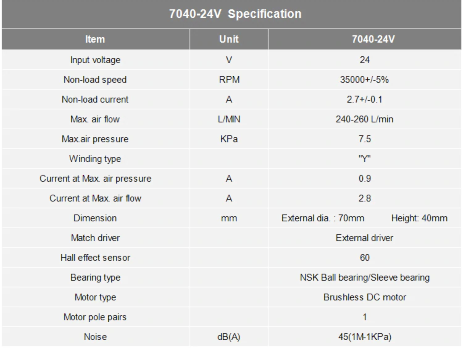
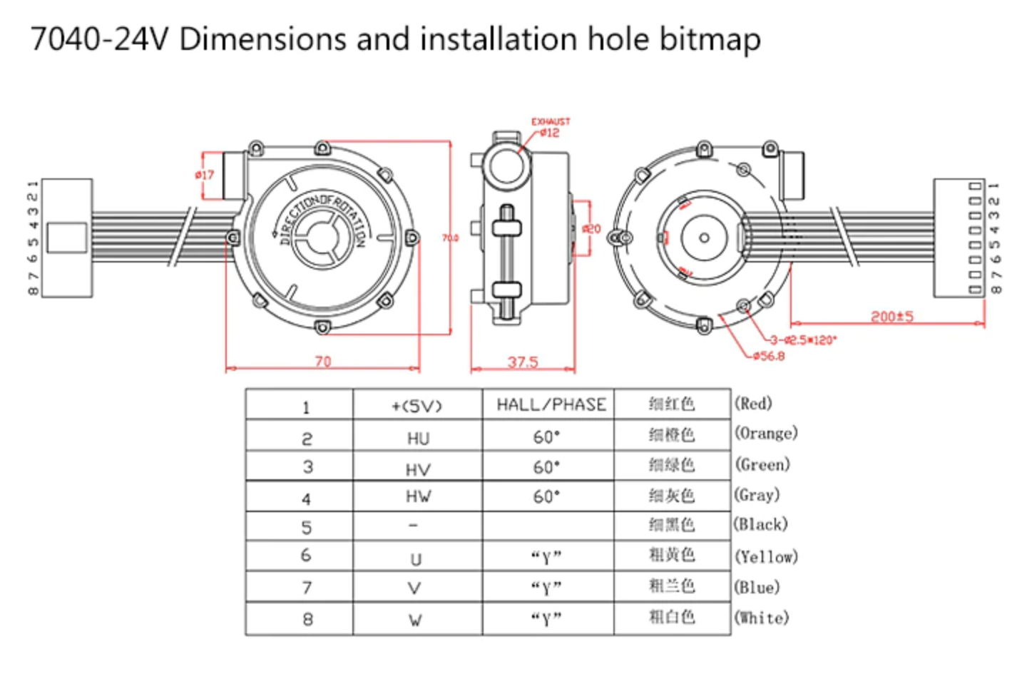
                                        HI all. so i have finished my first CoreXY printer with an duet3 6hc controller and id like to install a big centrifugal fan/blower as part cooling fan. Its a brushless 7040 fan (https://www.aliexpress.com/item/10000048326249.html?spm=a2g0o.cart.0.0.45413c00nJsmPg&mp=1) which needs to be connect with an extra driver.

                                        So I have 2 questions
                                        (I started with an Ender 3 V2 a year ago and well I have constantly been learning 🙂 )

                                        1. Do i need any extra precautions connecting the driver and blower to the duet3 board? (its rated max. 3A /peak 6A which should be covered by out_1-out_3 right? (Please screenshots for specs)

                                        2. is the wiring correct? (Please screenshots for specs)
                                          a) 24v from either OUT_1,OUT_2 or OUT_3
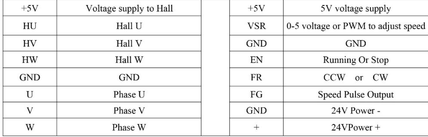
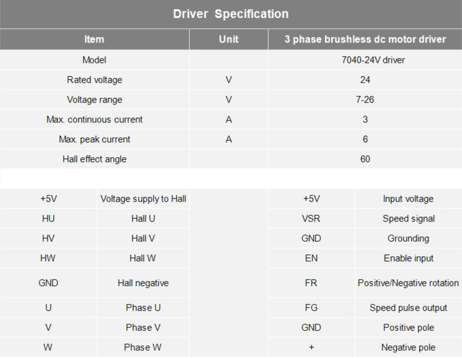
                                          b) driver control from 5v PWM (out9)
                                          driver --> Duet3 (5V PWM(out9))
                                          +5V --> 5V_EXT
                                          VSR --> out9
                                          GND --> GND

                                        What do i need to add to the config.g anything special or just like every other fan?

                                        Your help is appreciated. Thanks

                                        Screenshot 2021-06-02 at 18.56.52.png Screenshot 2021-06-02 at 18.57.01.png Screenshot 2021-06-02 at 18.57.13.png

                                        dc42undefined 1 Reply Last reply Reply Quote 0
                                        • dc42undefined
                                          dc42 administrators @Cassiopeia
                                          last edited by

                                          @cassiopeia that looks OK, assuming that the VSR input accepts a PWM signal.

                                          Duet WiFi hardware designer and firmware engineer
                                          Please do not ask me for Duet support via PM or email, use the forum
                                          http://www.escher3d.com, https://miscsolutions.wordpress.com

                                          Cassiopeiaundefined 1 Reply Last reply Reply Quote 0
                                          • Cassiopeiaundefined
                                            Cassiopeia @dc42
                                            last edited by Cassiopeia

                                            @dc42
                                            thanks for your quick response. upon further research the VSR pin takes 0-5V or PWM for the speed input of the fan. so i guess this will work with out9?!
                                            Screenshot 2021-06-02 at 21.23.50.png

                                            akuma211undefined 1 Reply Last reply Reply Quote 1
                                            • First post
                                              Last post
                                            Unless otherwise noted, all forum content is licensed under CC-BY-SA