Duet3D Logo Duet3D
    • Tags
    • Documentation
    • Order
    • Register
    • Login

    12864 display (ST7920) on Duet 3 Mini5+

    Scheduled Pinned Locked Moved
    Duet Hardware and wiring
    10
    31
    3.6k
    Loading More Posts
    • Oldest to Newest
    • Newest to Oldest
    • Most Votes
    Reply
    • Reply as topic
    Log in to reply
    This topic has been deleted. Only users with topic management privileges can see it.
    • DIY-O-Sphereundefined
      DIY-O-Sphere @DIY-O-Sphere
      last edited by

      @dc42
      Can you please take a short look at the wiring diagram?
      The LCD works fine now, but I can't get the SD card reader to work.
      My best guess is, it has someting to do with SPI2_CS0 on the output.
      I already tried connecting to SPI2_CD and SPI2_CS3, but no success.
      (I don't use the external SD Card, but I would like to have the wiring right.)

      (UTC+1)

      dc42undefined 1 Reply Last reply Reply Quote 0
      • dc42undefined
        dc42 administrators @DIY-O-Sphere
        last edited by dc42

        @DIY-O-Sphere, are you really saying that the LCD works if you use F1999999 in the M918 command, but not if you use F2000000 ? That sounds most unlikely.

        Three comments:

        1. The level shifter IC should be 74HCT08, not 74HC08.
        2. You should ground the unused 1A and 1B inputs of the 74HCT08, or connect them to +5V.
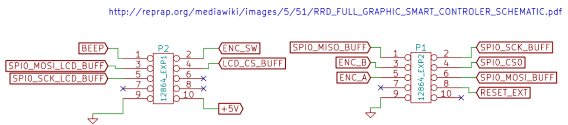
        3. The Duet 3 Mini has a card detect input, SPI2_CD in your diagram. You should connect that to the card detect output of your LCD if it has one. It's probably EXP2 pin 7 on your LCD. Caution, you must not apply 5V to SPI2_CD. So check that EXP2 pin 7 is connected to ground when the SD card is inserted, and is floating when it is not. If the LCD doesn't support the card detect output, ground the SPI2_CD pin instead.

        HTH David

        Duet WiFi hardware designer and firmware engineer
        Please do not ask me for Duet support via PM or email, use the forum
        http://www.escher3d.com, https://miscsolutions.wordpress.com

        DIY-O-Sphereundefined 1 Reply Last reply Reply Quote 0
        • DIY-O-Sphereundefined
          DIY-O-Sphere @dc42
          last edited by

          @dc42 said in 12864 display (ST7920) on Duet 3 Mini5+:

          The level shifter IC should be 74HCT08, not 74HC08.

          It's a typo IC is 74HCT08

          You should ground the unused 1A and 1B inputs of the 74HCT08, or connect them to +5V.

          I will do this later in a soldered pcb board

          The Duet 3 Mini has a card detect input, SPI2_CD in your diagram. You should connect ............

          782439d4-5201-4fa9-bf77-b8454ad82495-grafik.png

          You are briliant
          It is not shown in the diagram but it is present. (The Maestro didn't have the connector).
          When the card is inserted it changes from 0.4V to 0V. I think that should be fine.
          I have currently connected SPI2_CD to ground and it works.
          Thanks a lot.

          I still have one final question.
          I have an accelerometer that I want to connect to the PanelDue connector.
          b8390d27-ae24-4740-83af-0a849ee55e9e-grafik.png
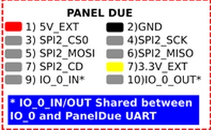
          Will this work in combination with the LCD sd card reader (same SPI bus)?
          I will not run both at the same time.

          (UTC+1)

          dc42undefined 1 Reply Last reply Reply Quote 0
          • dc42undefined
            dc42 administrators @DIY-O-Sphere
            last edited by dc42

            @diy-o-sphere the accelerometer is normally connected to the temperature daughter board connector. I think it should be possible to use the PanelDue connector instead, but I haven't tested that. It should work OK with the LCD card reader if the cables are short.

            Duet WiFi hardware designer and firmware engineer
            Please do not ask me for Duet support via PM or email, use the forum
            http://www.escher3d.com, https://miscsolutions.wordpress.com

            DIY-O-Sphereundefined 1 Reply Last reply Reply Quote 0
            • DIY-O-Sphereundefined
              DIY-O-Sphere @dc42
              last edited by

              @dc42

              the accelerometer is normally connected to the temperature daughter board connector.

              My pIan was, that by using IO.0 only one plug is required.
              But it's just to play around.
              I will buy the new toolboard as soon as it is available here.
              Thanks for the announcement👍
              I don't feel disadvantaged, quite the opposite.

              (UTC+1)

              1 Reply Last reply Reply Quote 0
              • PCRundefined
                PCR
                last edited by

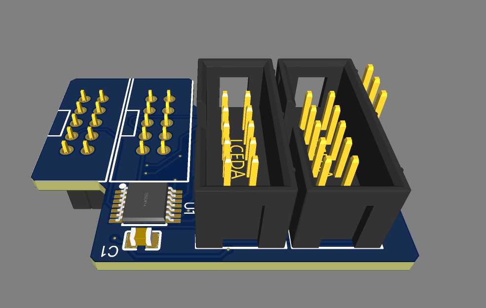
                Hello i am in the process of making a small Production run based on @DIY-O-Sphere schematic. IT will be Board which will be directly olugged Into the Mini;)
                Please upvote If you want one!

                PCRundefined 1 Reply Last reply Reply Quote 6
                • PCRundefined
                  PCR @PCR
                  last edited by

                  @pcr

                  7127750a-6cba-4566-904d-cb953a1097cb-grafik.png

                  7c3b49b7-9907-4405-b353-81a89670e9d4-grafik.png

                  PCRundefined kgolgerundefined 2 Replies Last reply Reply Quote 3
                  • PCRundefined
                    PCR @PCR
                    last edited by PCR

                    @pcr

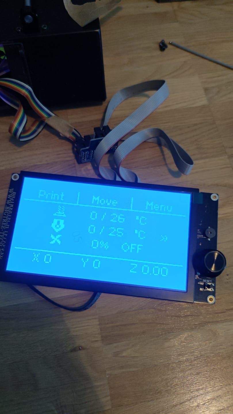
                    The adapters are here and they work. I tested it with the classic Display, the BTT 35 and the BTT 70.

                    Please PN if you want one! You can choose between a plugin type or a "extension" one 😉 For plugin see the image above

                    WhatsApp Image 2021-07-05 at 10.41.58.jpeg WhatsApp Image 2021-07-05 at 10.41.584.jpeg WhatsApp Image 2021-07-05 at 10.41.585.jpeg

                    MatixYoundefined 1 Reply Last reply Reply Quote 3
                    • MatixYoundefined
                      MatixYo @PCR
                      last edited by

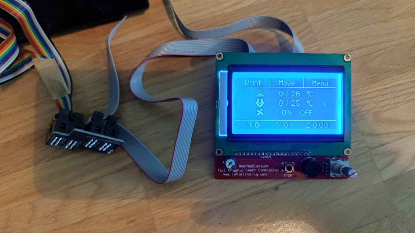
                      @pcr how much is it?

                      PCRundefined 1 Reply Last reply Reply Quote 0
                      • PCRundefined
                        PCR @MatixYo
                        last edited by

                        @matixyo

                        6€ with connectors.

                        4€ untracked shipping. 7€ tracked

                        MatixYoundefined Giannivoxundefined 2 Replies Last reply Reply Quote 0
                        • MatixYoundefined
                          MatixYo @PCR
                          last edited by

                          @pcr not bad

                          1 Reply Last reply Reply Quote 0
                          • Giannivoxundefined
                            Giannivox @PCR
                            last edited by

                            @pcr Hi, adapters in compatible with mks mini12864 v2.1?
                            thanks

                            DIY-O-Sphereundefined 1 Reply Last reply Reply Quote 1
                            • DIY-O-Sphereundefined
                              DIY-O-Sphere @Giannivox
                              last edited by

                              @giannivox
                              If the LCD has a ST7567 chip, the adapter is not required.

                              (UTC+1)

                              1 Reply Last reply Reply Quote 1
                              • kgolgerundefined
                                kgolger @PCR
                                last edited by

                                @pcr

                                Does the adapter also work with a Duet2 Wifi (Ref. 1.04, Firmware 3.3)?

                                DIY-O-Sphereundefined 1 Reply Last reply Reply Quote 0
                                • DIY-O-Sphereundefined
                                  DIY-O-Sphere @kgolger
                                  last edited by

                                  @kgolger
                                  The input will not match directly by plug. You have to wire them pin by pin.
                                  @PCR also provides a wired version

                                  (UTC+1)

                                  DIY-O-Sphereundefined 1 Reply Last reply Reply Quote 0
                                  • DIY-O-Sphereundefined
                                    DIY-O-Sphere @DIY-O-Sphere
                                    last edited by

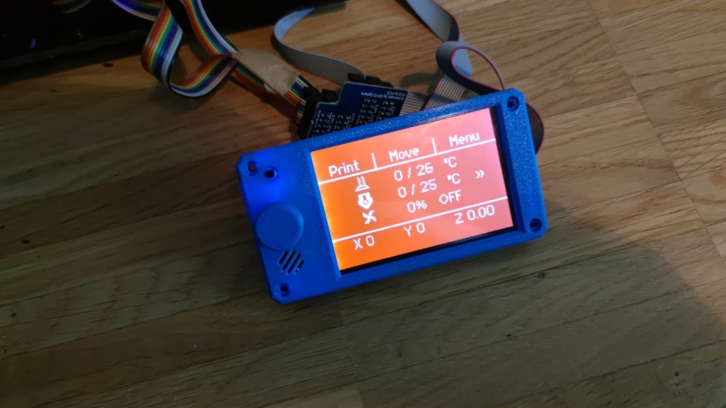
                                    Thanks to the support of @pcr i was able to replace my prototype board.
                                    Finally a clean wiring!

                                    7f176749-8ae2-49dc-b9bf-5452a27f8f4d-grafik.png

                                    (UTC+1)

                                    tecnoundefined 1 Reply Last reply Reply Quote 1
                                    • DIY-O-Sphere
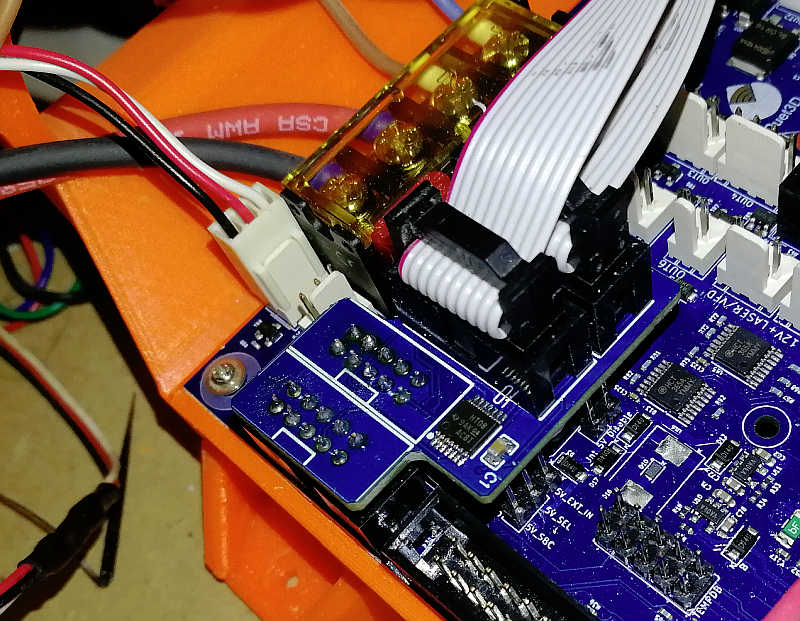
undefined DIY-O-Sphere referenced this topic
                                    • tecnoundefined
                                      tecno @DIY-O-Sphere
                                      last edited by

                                      @DIY-O-Sphere

                                      Hello , just got adapterboards from PCR and I can not get things to work OK here.
                                      Connected as below picture No shorts on 3-pin.

                                      DSC_0406.JPG

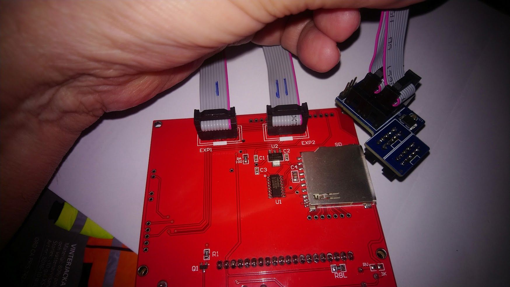
                                      ; General preferences
                                      M918 P1 E-4 F1999999
                                      M575 P1 S0 B57600 ; enable support for PanelDue
                                      G90 ; send absolute coordinates...
                                      M83 ; ...but relative extruder moves
                                      M550 P"BigDelta"

                                      DIY-O-Sphereundefined 1 Reply Last reply Reply Quote 0
                                      • DIY-O-Sphereundefined
                                        DIY-O-Sphere @tecno
                                        last edited by DIY-O-Sphere

                                        @tecno
                                        As far as I can tell, the cables on the display are plugged in backwards. I think the noses on the plugs are under the cable and look upwards. But the noses must be above the white boxes.

                                        (UTC+1)

                                        tecnoundefined 1 Reply Last reply Reply Quote 0
                                        • tecnoundefined
                                          tecno @DIY-O-Sphere
                                          last edited by tecno

                                          @DIY-O-Sphere
                                          No go that way either. (Funny thing is that the display had the nose notches the other way! from factory)

                                          S O R R Y MY BAD Now working

                                          DIY-O-Sphereundefined 1 Reply Last reply Reply Quote 0
                                          • DIY-O-Sphereundefined
                                            DIY-O-Sphere @tecno
                                            last edited by DIY-O-Sphere

                                            @tecno
                                            The jumper is only required to enable the sd-card reader.

                                            (UTC+1)

                                            tecnoundefined 1 Reply Last reply Reply Quote 0
                                            • First post
                                              Last post
                                            Unless otherwise noted, all forum content is licensed under CC-BY-SA