Duet3D Logo Duet3D
    • Tags
    • Documentation
    • Order
    • Register
    • Login

    Vertical lines vs. geared extruders

    Scheduled Pinned Locked Moved
    Tuning and tweaking
    vertical banding
    26
    89
    9.7k
    Loading More Posts
    • Oldest to Newest
    • Newest to Oldest
    • Most Votes
    Reply
    • Reply as topic
    Log in to reply
    This topic has been deleted. Only users with topic management privileges can see it.
    • CCS86undefined
      CCS86 @ajdtreyd
      last edited by

      @ajdtreyd said in Vertical lines vs. geared extruders:

      @donstauffer

      If you want to determine if it's the extruder then do several test prints changing ONLY the extrusion width. This way the motion system does exactly the same thing every time, but the extruder is moving filament faster as the EW increases. If it's the extruder, the period of your sine wave will decrease (or if you prefer, the frequency will increase) as the extrusion rate increases. If the sine wave stays the same the issue is somewhere in the motion system.
      I had the vertical line artifact on my delta in the past and resolved it by replacing the smooth bearing idlers and belt with genuine Gates belt and toothed idlers.
      Of course once those artifacts were gone I was able to see the next set of subtler artifacts. And on it goes ...

      You would have to make large changes in flow to have observable changes in drive gear speed.

      zaptaundefined ajdtreydundefined 2 Replies Last reply Reply Quote 0
      • zaptaundefined
        zapta @CCS86
        last edited by

        Stumbled recently upon this video that claim that the meshing of the two gears of dual gear drives creates extrusion artifacts.

        https://www.youtube.com/watch?v=32dTLRNIYmw

        botundefined 1 Reply Last reply Reply Quote 1
        • ajdtreydundefined
          ajdtreyd @CCS86
          last edited by

          @ccs86

          He did say he was observing that sine wave pattern in "microscopic pictures". I assume he meant he had taken the pics through a microscope and not that the pics themselves were microscopic. Anyway, I assume he has the means to distinguish those small changes (a microscope) and the simple, quick test would be worth doing if only to eliminate the extruder.

          CCS86undefined 1 Reply Last reply Reply Quote 0
          • CCS86undefined
            CCS86 @ajdtreyd
            last edited by

            @ajdtreyd said in Vertical lines vs. geared extruders:

            @ccs86

            He did say he was observing that sine wave pattern in "microscopic pictures". I assume he meant he had taken the pics through a microscope and not that the pics themselves were microscopic. Anyway, I assume he has the means to distinguish those small changes (a microscope) and the simple, quick test would be worth doing if only to eliminate the extruder.

            Fair point.... and especially if it was a single wall print, you could definitely run a pretty large flow modifier without consequence.

            1 Reply Last reply Reply Quote 0
            • botundefined
              bot @zapta
              last edited by

              @zapta read up a few posts we've been discussing that.

              I've confirmed a very faint wood grain pattern on my printer with bondtech gears and non-bowden extruder.

              *not actually a robot

              mrehorstdmdundefined 1 Reply Last reply Reply Quote 0
              • mrehorstdmdundefined
                mrehorstdmd @bot
                last edited by

                rq3 at has a couple threads on an extruder he built that is very light and propels the filament by rolling threads into it. See:

                https://reprap.org/forum/read.php?424,883786
                and
                https://reprap.org/forum/read.php?424,885022,885049

                https://drmrehorst.blogspot.com/

                1 Reply Last reply Reply Quote 2
                • hackinistratorundefined
                  hackinistrator
                  last edited by

                  i have yet to see any "perfect" extruder drive , all current extruders have drawbacks .
                  i think the current best would be to use large (like lgx) hobbed gear without the dual drive .

                  this extruder looked interesting
                  https://www.youtube.com/watch?v=OVhw3XlrDuY

                  but mechanical tolerances on it need to be perfect .

                  i have stratasys fortus machine at work and it is also generating extrusion artifacts .

                  mrehorstdmdundefined 1 Reply Last reply Reply Quote 0
                  • mrehorstdmdundefined
                    mrehorstdmd @hackinistrator
                    last edited by

                    @hackinistrator at 49 seconds into the video there's a close-up of the print that seems to have the same vertical lines we've been talking about here (or maybe they are defined by the segment length in the STL file?).

                    https://drmrehorst.blogspot.com/

                    Phaedruxundefined 1 Reply Last reply Reply Quote 0
                    • Phaedruxundefined
                      Phaedrux Moderator @mrehorstdmd
                      last edited by

                      @mrehorstdmd Looks a bit like STL segmentation to me.

                      Z-Bot CoreXY Build | Thingiverse Profile

                      Notepadundefined 1 Reply Last reply Reply Quote 0
                      • kb58undefined
                        kb58
                        last edited by kb58

                        On my printer, I see faint vertical lines on the sides of a printed test cube, but only in the Y direction, not the X, so suspect printer frame deflection/ringing in the Y axis.

                        Are you guys seeing the patterns being discussed irrespective of print direction? If it really is an extruder issue, print direction would not matter. If it does, then frame stiffness may be contributing.

                        Scratch-built 350mmx350mm coreXY, linear rails, ballscrews, 3 Z axis, Duet3 6HC, v3.3, Tool Board v1.1, BondTech LGX + Mosquito hot end

                        1 Reply Last reply Reply Quote 0
                        • DonStaufferundefined
                          DonStauffer @bot
                          last edited by

                          @bot I replaced the belt even though it was only very slightly frayed.

                          The vertical artifact didn't go away, but may have faded some. But the flatness of my walls improved pretty significantly. So I think you're right that belts need to be replaced more frequently than it seems. It really made a difference. Just not the one I was looking for. But it's still good.

                          botundefined 1 Reply Last reply Reply Quote 0
                          • botundefined
                            bot @DonStauffer
                            last edited by

                            @donstauffer I think I need to try the same thing! Thanks for the feedback.

                            *not actually a robot

                            1 Reply Last reply Reply Quote 0
                            • Notepadundefined
                              Notepad @Phaedrux
                              last edited by

                              @phaedrux Im unfortunately having that issue on straight walls. so I can confirm its not STL deresolution. honestly pulling my hair out trying to find out why I get vertical lines so blatant on straight walls.

                              The real bamboo printer manufacturer

                              1 Reply Last reply Reply Quote 0
                              • DonStaufferundefined
                                DonStauffer
                                last edited by

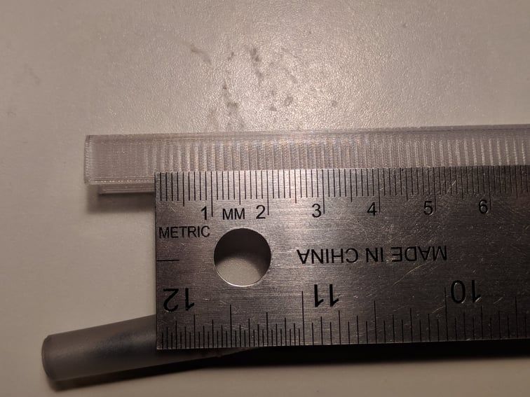
                                This is a first layer, in Hatchbox transparent PETG, printed at 12 mm/sec, showing the vertical artifact. I have now replaced all hot end parts and all movement parts, with the only exception being the linear rails, which are smooth as silk. I have not been able to solve this problem, at all, but I have concluded it is not likely to be a mechanical problem.

                                f01739a4-d284-4517-b40d-6fa1dfb3d1ed-image.png

                                1 Reply Last reply Reply Quote 0
                                • DonStaufferundefined
                                  DonStauffer
                                  last edited by

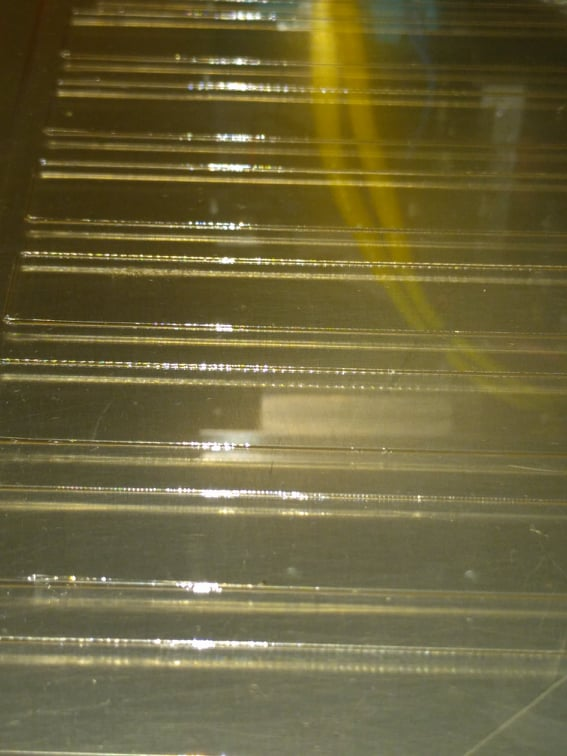
                                  Another remarkable example in transparent PETG, printed at about 45 mm/sec:
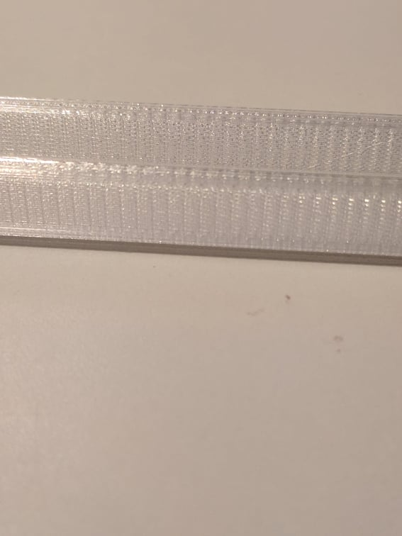
                                  56c92f28-9074-4006-bab2-64f7384e8527-image.png

                                  DonStaufferundefined 1 Reply Last reply Reply Quote 0
                                  • DonStaufferundefined
                                    DonStauffer @DonStauffer
                                    last edited by

                                    @donstauffer Artifact.jpg

                                    o_lampeundefined droftartsundefined 3 Replies Last reply Reply Quote 0
                                    • o_lampeundefined
                                      o_lampe @DonStauffer
                                      last edited by o_lampe

                                      @donstauffer
                                      those lines are pretty impressive. 😦
                                      I can't see what the printdirection was, but I guess it was "left-right"? Otherwise it indicates your nozzle isn't exactly true to the bed and more filament is squished to one side then the other..The cross section would look like a seesaw

                                      DonStaufferundefined 1 Reply Last reply Reply Quote 0
                                      • o_lampeundefined
                                        o_lampe @DonStauffer
                                        last edited by

                                        @donstauffer
                                        some math wizard should be able to calculate what part of the equation is synchron with that line distance.
                                        We'd need to calculate the amount of extrusion ( layer height, layerwidth, nozzle) and correlate it with the extruder drive train.
                                        Is it a wobbling drive gear or a current control issue of the stepper driver or what?

                                        1 Reply Last reply Reply Quote 0
                                        • droftartsundefined
                                          droftarts administrators @DonStauffer
                                          last edited by

                                          @donstauffer I think you have missed out on a large part of this thread. See from here: https://forum.duet3d.com/post/240216
                                          Watch these two videos, particularly the second one:
                                          https://www.youtube.com/watch?v=dL6u0UwPJOQ
                                          https://www.youtube.com/watch?v=32dTLRNIYmw

                                          Print this object and see if you get the 'woodgrain' effect: https://mihaidesigns.com/pages/inconsistent-extrusion-test

                                          If you get the woodgrain effect, then you'll know if the issue is the extruder. If the lines line up, it's something in your X and Y movement.

                                          If you do get a woodgrain effect, he explains calculating the extrusion distance between artefacts in the second video from about 1:50, which can help pinpoint what's causing the issue. It looks like you have 13 artefacts in 20mm, which is quite a lot shorter than the extruder gear cogging issue, but depends on extrusion width. It may be the extruder motor full step distance, or the extruder gear teeth distance. Maybe post the response to M115 and config.g, too.

                                          Ian

                                          Bed-slinger - Mini5+ WiFi/1LC | RRP Fisher v1 - D2 WiFi | Polargraph - D2 WiFi | TronXY X5S - 6HC/Roto | CNC router - 6HC | Tractus3D T1250 - D2 Eth

                                          DonStaufferundefined 1 Reply Last reply Reply Quote 0
                                          • DonStaufferundefined
                                            DonStauffer @o_lampe
                                            last edited by

                                            @o_lampe I don't really understand. It's symmetrical, so it doesn't matter what the print direction was.

                                            1 Reply Last reply Reply Quote 0
                                            • First post
                                              Last post
                                            Unless otherwise noted, all forum content is licensed under CC-BY-SA