PWM to 10V via e0heater always gives 10V
-
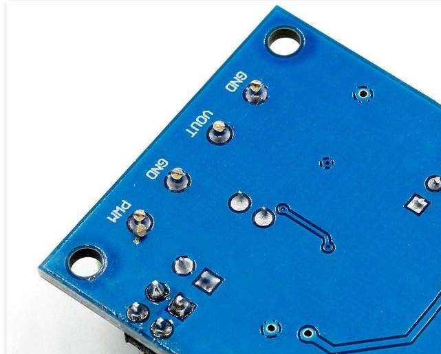
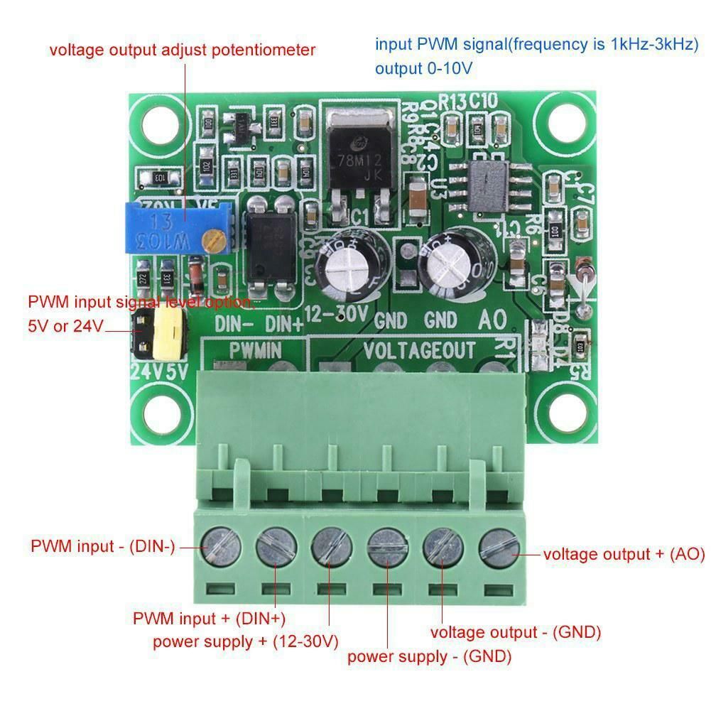
@cjm I agree, from the photo it appears that it has an opto isolator for the input. So why is there continuity between the PWM input ground and the output ground?
Duet WiFi hardware designer and firmware engineer
Please do not ask me for Duet support via PM or email, use the forum
http://www.escher3d.com, https://miscsolutions.wordpress.com -
@dc42 I think I found a picture of the back of the board, and indeed, both the input and output GND connections are to the same net!
Ref: Link.
(And in this photo, PWM might also be shorted to ground Ha ha)
SeemeCNC Rostock Max V3 converted to V3.2 with a Duet2 Ethernet Firmware 3.2 and SE300
-
@larsw I tried to use a similar type for an older CNC controller of mine and didn't have any luck. I eventually found and used this type which worked:
Available from the usual places. -
As a side note, this board reminds me of a similar project by egon.net https://forum.duet3d.com/topic/21680/designing-a-pwm-to-analog-mini-board-for-fans
-
@cjm I tried the pull resistor (4.7k) and it worked perfectly.
Only issue now is, that the 0-10V output max'es out at 8.6V, but I read somewhare that the converter - even though the specs says VIN 12V to 24V needs least 14,6V to reach 10V in output signal, and my powersupply is 12,8V.
8,6V is close enough - my spindle reaches to max speed at 9V.
-
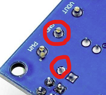
@alankilian they've made a mistake with that design IMO, by sharing the ground plane with both ground pins even though the input is optically isolated.
I would be tempted to cut the 4 fingers that join each of the pins I have marked to the ground plane, and connect them together with a wire instead.
-
@larsw said in PWM to 10V via e0heater always gives 10V:
@cjm I tried the pull resistor (4.7k) and it worked perfectly.
Only issue now is, that the 0-10V output max'es out at 8.6V, but I read somewhare that the converter - even though the specs says VIN 12V to 24V needs least 14,6V to reach 10V in output signal, and my powersupply is 12,8V.
8,6V is close enough - my spindle reaches to max speed at 9V.
That's GREAT news!
Thanks for keeping up with our ideas and letting us know you got it working.
If you want to get to 9 Volts, you can try adjusting the potentiometer on the board.
SeemeCNC Rostock Max V3 converted to V3.2 with a Duet2 Ethernet Firmware 3.2 and SE300
-
@larsw Good news! Glad to hear it’s all working now…
-
@alankilian said in PWM to 10V via e0heater always gives 10V:
Thanks for keeping up with our ideas and letting us know you got it working.
I hope somebody else can use these findings. The converter seems to be pretty common.
If you want to get to 9 Volts, you can try adjusting the potentiometer on the board.
This is with the potentioneter at max, but as I said - good enough.
-
@educatingsavvas
I just wired up one of these and it works too.One thing to note is that using less than 3000hz seems to result in the generation of a 0-10v signal that the VFD sees as oscillating and then it changes frequencies a lot. It ramps up and down 10’s of hertz.