Help with new custom printer - Prints have ringing around them
-
If haven't PID tuned your bed heater yet, now is the time. Bang bang controlled heating can cause enough expansion and reduction of the bed heater that you will get z banding artifacts.
-
This post is deleted! -
@mrawesome987 well this type of linear guide uses C shaped bushings and as far the rods are mounted on Aluprofile that is not straight in terms of hundreds of millimeter , so they can go slightly out of alignment .
-
@mrawesome987 glad you found the problem, it is looking a lot better
") do the lead screws still appear bent as they move on the machine? or has that gone now? as @oliof has suggested a bed PID tune is next it`s easy and most importantly free to do!
do the lead screws still appear bent as they move on the machine? or has that gone now? as @oliof has suggested a bed PID tune is next it`s easy and most importantly free to do! -
@jumpedwithbothfeet said in Help with new custom printer - Prints have ringing around them:
@mrawesome987 glad you found the problem, it is looking a lot better
do the lead screws still appear bent as they move on the machine? or has that gone now? as @oliof has suggested a bed PID tune is next it`s easy and most importantly free to do!The lead screws are definitely still looking bent. I'd like to replace them.
I am looking at the Misumi lead screws, but I'm having a hard time speccing what I need. The lead on my current screws is 2.54 mm, which is probably a bit low, right? They offer carbon steel and stainless. Any advantage to carbon steel?
Edit: I did PID tune the bed when I first configured it, although I PID tuned it for 60C, and I've been running it at 90C. Is that an issue?
-
@mrawesome987 now check this video on fixing the Z surface smoothness:
https://www.youtube.com/watch?v=a3oQy6v3MrA -
@mrawesome987, here is a printer that also has that Z sync belt so probably the idea is feasible if you make it right.
-
That z sync belt is interesting, but I'm not sure why you'd want to use that instead of a single motor driving both screws, which would eliminate any potential problems with the motor interactions. If getting sufficient torque to lift the bed is the issue, one higher torque motor would probably cost less than two smaller motors, and then you'd only need one cable and driver.
-
@mrehorstdmd said in Help with new custom printer - Prints have ringing around them:
but I'm not sure why you'd want to use that instead of a single motor
Lower backlash since each motor holds on the exact microstep?
Possibly could keep the belt loose and use it to avoid large skew when the motors are off, with automatic two points bed leveling on print start to get the motors in perfect sync.
-
@zapta I have a machine with two Z screws that uses a single drive motor to lift the X axis. It absolutely never tilts. Over the last 6 or 7 years that the printer has been in use I've had to re tram the X axis two or three times after taking the X axis off the machine for modifications.
If you use two motors and leave the belt loose, you're allowing the motors to move independently, a small amount (a backlash amount?). If you have to run a sync routine to force the screws back into sync, what did you gain by adding the belt?
-
@mrehorstdmd I agree with this I think.
My original thinking with the sync belt and two motors was that it would be beneficial in two ways:
- More torque to move the bed frame
- Sync the two lead screws so that they can't skip steps (or at least can't skip steps individually)
- Remove the possibility of turning one side without the other accidentally
The more I think about it, the more I am interested in moving to a single motor setup, with a much smaller pulley on the motor. Mostly for the reasons below:
- Probably more consistent that two motors?
- Remove the weight from directly on top of the motors, as it is now. Is this a huge issue? I'm not sure. Does anyone know what kind of force a Nema 23 can withstand long-term directly on the shaft?
As for the bent lead screw issue, I have reached out to the supplier I purchased them from a few months ago, and they seem to be willing to replace them. If that doesn't work out, I'll purchase new ones from a different, more reliable source.
While I wait for the issue above to resolve, I have been working to try to tune it to print decently. This has been causing some headache, but that's expected.
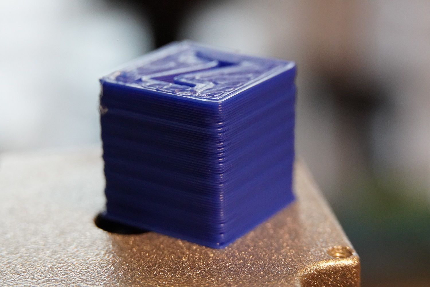
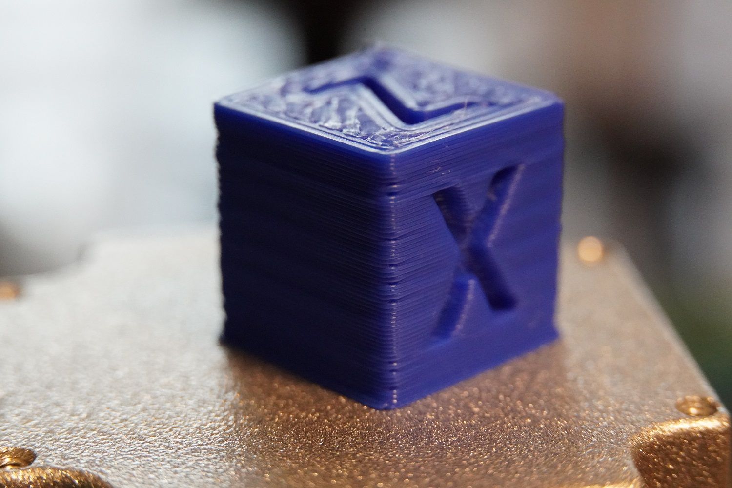
I have been testing by printing an XYZ 20mm cube, and the extrusion seems to be inconsistent. Most obviously is the corners.
The block on the left had PA set to .025, and the block on the right had PA set to .075. This produced a noticeable improvement, but does this sound like too much? I'm using a Hemera with Volcano, at .8mm nozzle.

Of course, I forgot to get the config.g and I'm at work now. I'll try to upload that later this afternoon.
Thanks for your help guys.
-
Here's my most recent config:
; Configuration file for Duet WiFi (firmware version 3.3) ; executed by the firmware on start-up ; ; generated by RepRapFirmware Configuration Tool v3.3.4 on Sat Oct 09 2021 23:56:58 GMT-0400 (Eastern Daylight Time) ; General preferences M575 P1 S1 B57600 ; enable support for PanelDue G90 ; send absolute coordinates... M83 ; ...but relative extruder moves M550 P"500x500" ; set printer name M669 K1 ; select CoreXY mode ; Network M552 S1 ; enable network M586 P0 S1 ; enable HTTP M586 P1 S0 ; disable FTP M586 P2 S0 ; disable Telnet ; Drives M569 P0 S0 ; physical drive 0 goes backwards M569 P1 S0 ; physical drive 1 goes backwards M569 P2 S1 ; physical drive 2 goes backwards M569 P4 S1 ; physical drive 4 goes forwards M584 X0 Y1 Z2 E4 ; set drive mapping M350 X16 Y16 Z16 E16 I1 ; configure microstepping with interpolation M92 X80.00 Y80.00 Z1259.84 E420.50 ; set steps per mm M566 X900.00 Y900.00 Z100.00 E2000.00 ; set maximum instantaneous speed changes (mm/min) M203 X8000.00 Y8000.00 Z120.00 E3500.00 ; set maximum speeds (mm/min) M201 X1200.00 Y1200.00 Z400.00 E5000.00 ; set accelerations (mm/s^2) M906 X1800 Y1800 Z2000 E1330 I30 ; set motor currents (mA) and motor idle factor in per cent M84 S30 ; Set idle timeout ; Axis Limits M208 X0 Y0 Z0 S1 ; set axis minima M208 X490 Y490 Z875 S0 ; set axis maxima ; Endstops M574 X1 S1 P"xstop" ; configure switch-type (e.g. microswitch) endstop for low end on X via pin xstop M574 Y2 S1 P"ystop" ; configure switch-type (e.g. microswitch) endstop for low end on Y via pin ystop M574 Z1 S2 ; configure Z-probe endstop for low end on Z M591 D0 P1 C"e1stop" S1 ; configure filament endstop for e1 extruder on low end ; Z-Probe / Compensation M950 S0 C"exp.heater3" ; create servo pin 0 for BLTouch M558 P9 C"^zprobe.in" H5 F120 T6000 ; set Z probe type to bltouch and the dive height + speeds G31 P500 X0 Y-35.56 Z2.650 ; set Z probe trigger value, offset and trigger height M557 X25:475 Y25:450 S25 ; define mesh grid M376 H5 ; Heaters M308 S0 P"bedtemp" Y"thermistor" T100000 B4138 ; configure sensor 0 as thermistor on pin bedtemp M950 H0 C"bedheat" T0 ; create bed heater output on bedheat and map it to sensor 0 M307 H0 B1 S1.00 ; enable bang-bang mode for the bed heater and set PWM limit M140 H0 ; map heated bed to heater 0 M143 H0 S120 ; set temperature limit for heater 0 to 120C M308 S1 P"e1temp" Y"thermistor" T100000 B4138 ; configure sensor 1 as thermistor on pin e1temp M950 H1 C"e1heat" T1 ; create nozzle heater output on e1heat and map it to sensor 1 M307 H1 B0 S1.00 ; disable bang-bang mode for heater and set PWM limit M143 H1 S280 ; set temperature limit for heater 1 to 280C ; Fans M950 F0 C"fan0" Q500 ; create fan 0 on pin fan0 and set its frequency M106 P0 S0 H-1 ; set fan 0 value. Thermostatic control is turned off ; Tools M563 P0 S"Extruder 1" D0 H1 F0 ; define tool 0 G10 P0 X0 Y0 Z0 ; set tool 0 axis offsets G10 P0 R0 S0 ; set initial tool 0 active and standby temperatures to 0C M572 D0 S0.025 ;set pressure advance ; Custom settings are not defined M501 -
@mrawesome987 said in Help with new custom printer - Prints have ringing around them:
@jumpedwithbothfeet Just wanted to make sure both steppers are always synced. Is that a problem? It made sense when I designed it, is it overkill?
Coupling them with a belt like that is generally fine but I don't like to do it above a flexible coupler as it puts sideways forces on them they may not be designed to handle.
Have you tried it without the belt?
As to lead screws there can be a large difference between cheap Chinese ones and ones from other sources.
Notice in the chart from the link above they specify things like the accuracy of movement per turn.
Also this company has "good, better, best" offerings. - so to speak.
Frederick
-
@fcwilt said in Help with new custom printer - Prints have ringing around them:
@mrawesome987 said in Help with new custom printer - Prints have ringing around them:
@jumpedwithbothfeet Just wanted to make sure both steppers are always synced. Is that a problem? It made sense when I designed it, is it overkill?
Coupling them with a belt like that is generally fine but I don't like to do it above a flexible coupler as it puts sideways forces on them they may not be designed to handle.
Have you tried it without the belt?
As to lead screws there can be a large difference between cheap Chinese ones and ones from other sources.
Notice in the chart from the link above they specify things like the accuracy of movement per turn.
Also this company has "good, better, best" offerings. - so to speak.
Frederick
Yes, one of my images above shows the difference with and without the belt tensioned. It was definitely a huge part of the problem, but the issue is still not 100% cured, which I attribute to the massively bent lead screws. I have ordered some solid couplers and am also getting replacement lead screws from the place I originally ordered them from. I am hopeful that they will be better, but if not, I'll order some from elsewhere. Thanks!
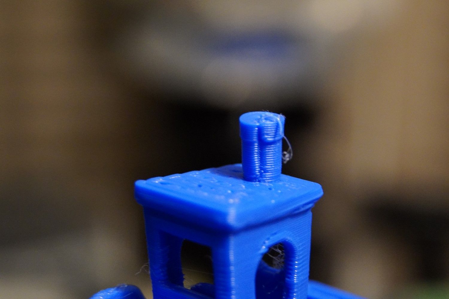
On my most recent XYZ cubes, I am still fighting the same quality issues, ignoring the Z wobble issue for now (since that's to blame on the lead screws). This is one of the most recent cubes:
I cant seem to get rid of the bad corners. I have tried both Pressure Advance (.025 up to .1), more retraction (currently at 2.5mm @ 3000mm/m), rotating the print on the bed (no real change), slower print (no change), etc.
Any suggestions?
Thanks!
-
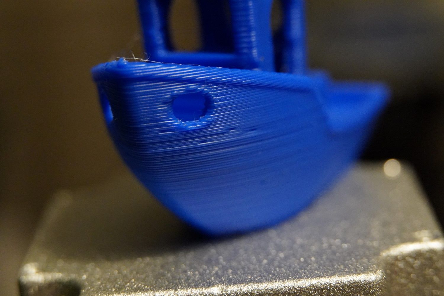
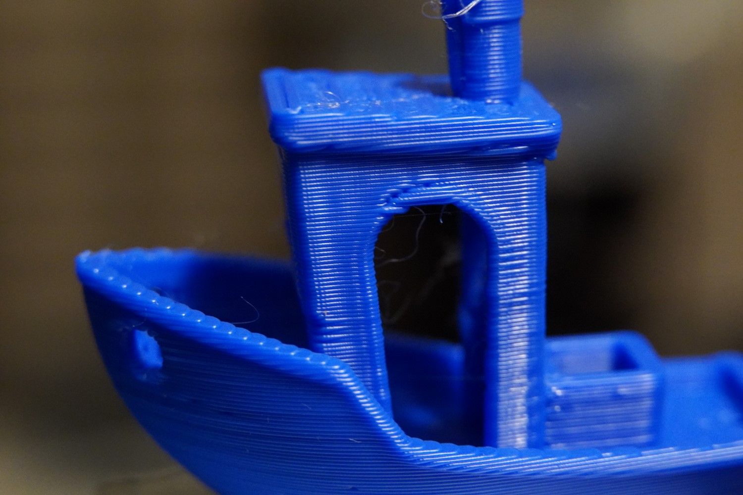
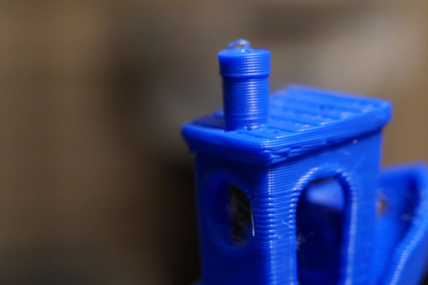
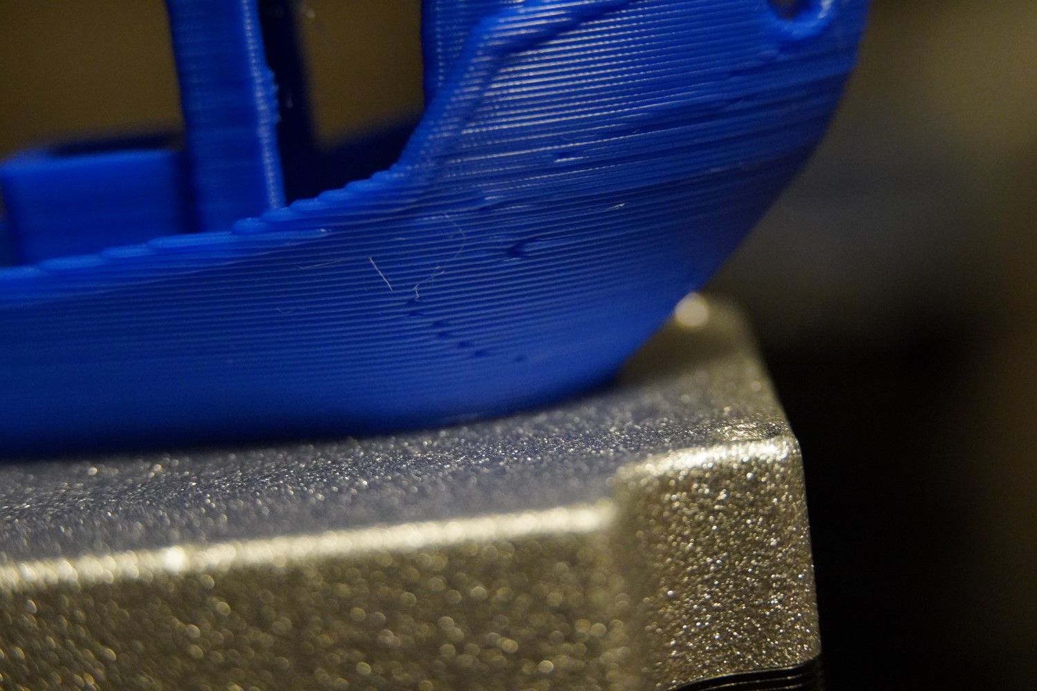
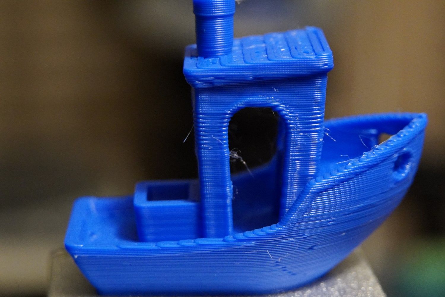
Benchy for reference:
-
@mrawesome987 did you remove the leadscrews to check them for straightness?