Want input on frame design
-
@mikeabuilder very cool. I haven't really thought about doing it all metal.
3030 vs 2040, which is stiffer?
-
@gnydick if your going big 4040, having built a core xy with 4040 its very ridged but heavy
-
I know of one self sourced ratrig build using 6060s even ... that's quite chonky, but for a large frame printer, why not overdo it a bit?
-
@oliof said in Want input on frame design:
I know of one self sourced ratrig build using 6060s even ... that's quite chonky, but for a large frame printer, why not overdo it a bit?
The trouble is, you lose XY travel unless you build the frame even bigger. 6060 will give you 40mm less travel in X and Y than say 4040, for a given outside frame size. Using mostly 2040 on my 600mm X 600mm frame, I only have about 370mm of travel in X and Y. 4040 would reduce that to around 330mm and 6060 would reduce it to 290mm. So if 2040 gives the requisite rigidity, then larger extrusion only has a downside by losing print volume but no upside.
-
@gnydick said in Want input on frame design:
3030 vs 2040, which is stiffer?
Depends how you load it.
Openbuilds show their section properties to be (all mm^4) (pdf from https://openbuilds.com/projectresources/how-to-calculate-v-slot
 -deflection.175/ but you need to be registered to download it)
- 20x20: 6.988E3
- 20x40: 48.163E3 and 12.305E3
- 20x60: 149.336E3 and 17.602E3
- 20x80: 336.24E3 and 22.938E3
Misumi show their section properties to be
- 20x20: 7.42E3 (https://uk.misumi-ec.com/vona2/detail/110302683830/)
- 20x40: 51.3E3 and 13.58E3 (https://uk.misumi-ec.com/vona2/detail/110302684350/)
- 30x30: 26.8E3 to 34.7E3 depending on section type (https://uk.misumi-ec.com/vona2/detail/110302686450/)
So, 20x40 in major axis bending is about 1.7x as stiff as 'standard' 30x30. In minor axis bending it's about 0.4x as stiff.
I can't find anyone quoting cross-sectional area, but axial stiffness will just be in proportion to cross-sectional area.
I can't find anyone quoting torsional parameters, but I'd expect the 20x40 to be significantly stiffer torsionally than the 30x30 because of the big central cell (tubes are good in torsion, and a large diameter thin-wall tube is much better than a small diameter thick-walled tube with the same quantity of material).
This all assumes like-for-like material. However, typical aluminium alloys are generally within about 5% of each other, so won't change the conclusion. There's much more variation in strength, so if you were worried about that you would need to think about the alloy.(https://www.engineeringtoolbox.com/properties-aluminum-pipe-d_1340.html)
-
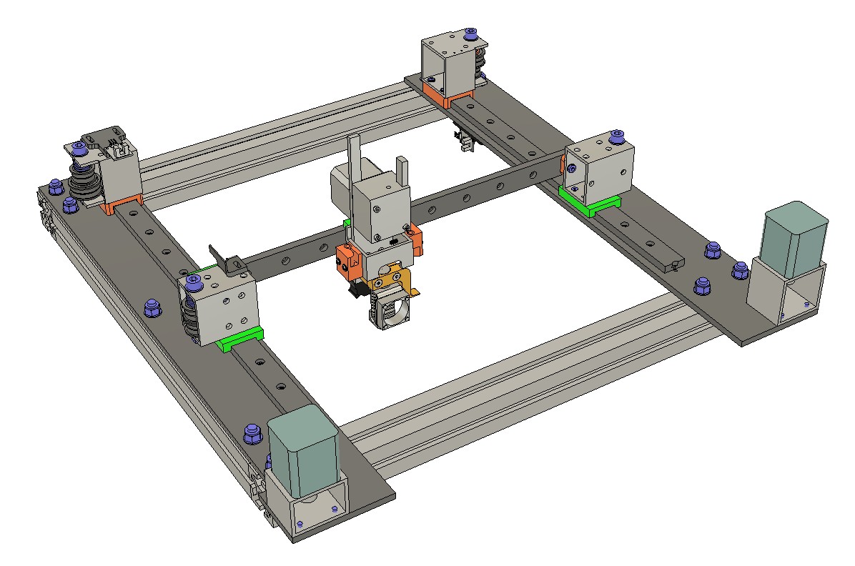
I took a slightly different approach to my corexy build. I wanted to design the XY stage to make it easy to align the Y axis guide rails, and that's easiest if they start in the same plane, so I built a 4040 square subframe, bolted on two pieces of cast tooling plate, and then the guide rails. This method ensures that the Y axis rails start in the same plane so I only had to align them in XY and not XYZ. Motor and pulley mounts are made from rectangular aluminum tubing, minimizing the machining required, and acting as heat sinks for the motors (but probably not important as the motors don't get hot anyway).
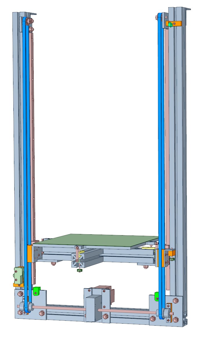
I used a belt lifted Z axis, about 700 mm long, with a 30:1 worm gear drive that doesn't move at all when Z motor power is cut. The bed assembly weighs about 3.5 kg and I have loaded the bed with 4 kg extra weight and the worm drive has no trouble lifting it.
The bed is a piece of 8mm cast tooling plate on a kinematic mount. The print surface is a piece of 0.7 mm PEI. The bed plate, heater, and PEI are all 300x300 but the plate has "ears" for the kinematic mount. I don't use mesh compensation because it isn't needed. The plate is flat and stays flat when heated, and the kinematic mount is stable. I only have to retram the bed if I take the Z axis apart- last time was over a year ago. It just works, every time, even after I transport the machine laying on its back in my car.
In many designs enclosure seems to be an afterthought and becomes difficult, especially when the XY stage is sitting on top of the frame. I used to print a lot of ABS so I designed the frame to allow easy enclosure by making it large enough that the XY stage can fit inside the printer's frame. Adding PC or plywood panels to the sides of the frame can increase rigidity, but I used double walled PC sheet commonly used to make greenhouses. It fits in the t-slot, provides thermal insulation, and allows light in and out of the printer but does nothing to improve rigidity of the frame. Front doors are polycarbonate sheet, the larger one held onto the frame by magnetic tape. I also installed white and UV lighting.
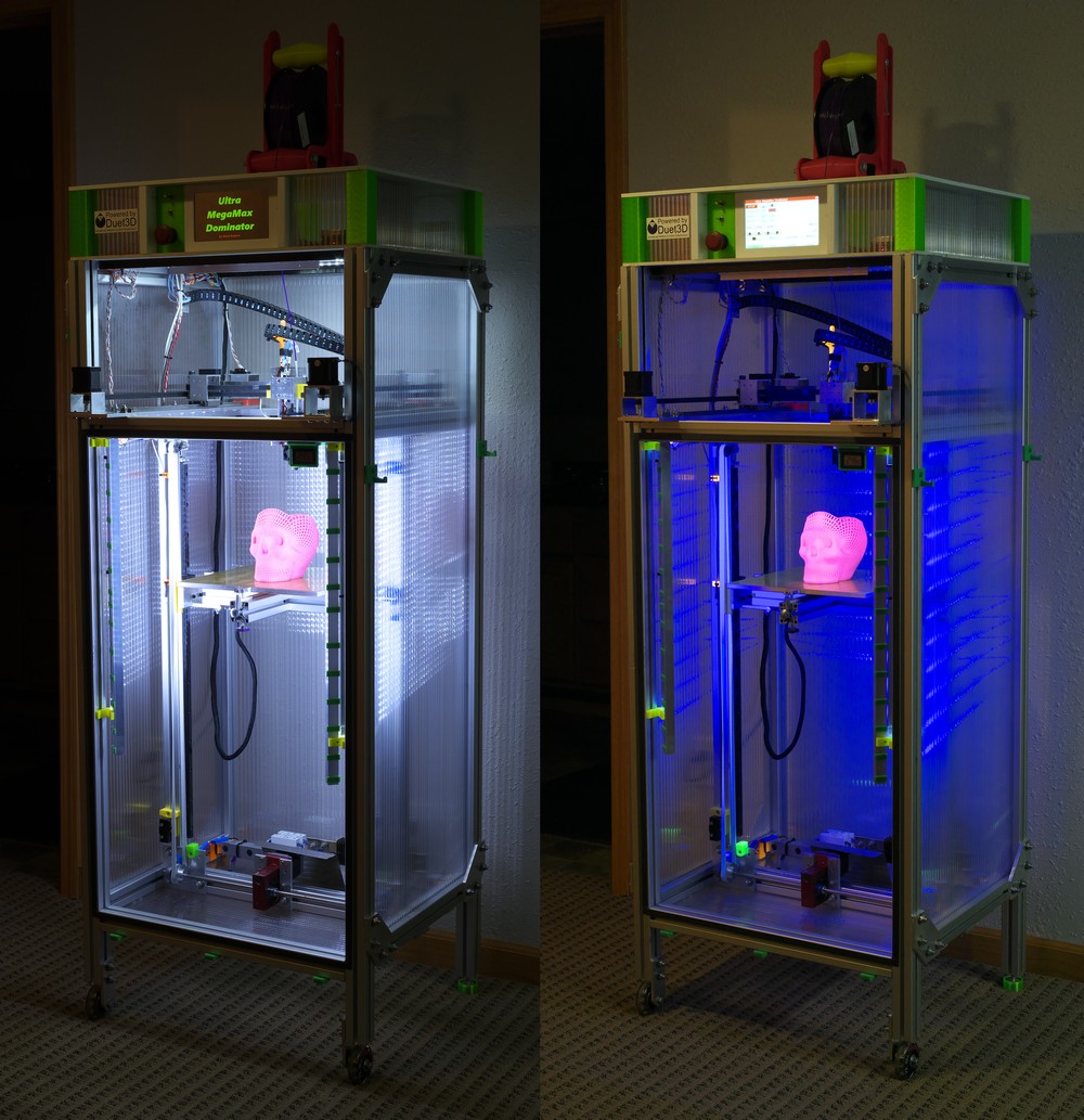
In a corexy machine, most of the wiring connects to the printer at the XY stage, so I put the electronics at the top to minimize cable lengths and to make it easy to access the electronics without having to crawl on the floor or turn the printer over.
-
@mrehorstdmd d,d,d,d,damn. That's impressive.
I'm trying to design it very simply, minimal machining if any. I'd like to use geometry to the utmost as the source of rigidity.
-
@gnydick Machining in UMMD (the corexy printer) was limited to cleaning up the edges of the bed and making the hole and slot for the kinematic mount, milling and drilling the teflon blocks for the kinematic mount, cleaning up edges of the rectangular tubing and drilling holes accurately, and squaring and matching lengths of the 4040 t-slot so the frame would squarely bolt together. There were probably one or two other simple operations on other parts as well, but nothing difficult, even on a manual milling machine.
-
most of my frame is 2040 and some 2020 , main cube is made of 500x500x1000 2040 with a few reinforcement in middle and other place , with a mix of 2040 and 2020 , this screenshot aint up to date fully unfortunately , i need one of these days to update everything !
-
A couple more random thoughts. Aluminium is preferable to plastic parts of you have access to the necessary machining capabilities. If you do need to print any parts, avoid PLA like the plague, especially if you live somewhere that has warm summers or if you want to use a heated enclosure. Use a more heat tolerant filament. In any case, I'd highly recommend using aluminium for all motor mounts. It's a good conductor of both heat and electricity so the entire frame will act as giant heat sink and the motors will run so much cooler. Also, it'll act as a ground plane for any static that might build up. On that topic, earth the frame - preferably in several places. Tie the frame to PSU gnd and make sure that the print head is also tied to gnd.
I'd also highly recommend that anything that carries idler pulleys or wheels is supported at both ends. Otherwise they'll twist under tension.
-
@deckingman yeah, the only access I have is if I use a CNC mail order service.
-
I designed my bulldog printer to not use any custom machined parts (and no structural 3D printed parts either). All custom metal was designed to be lasercut. I primarily used 1/8" (3mm) plate, with a few thicker parts. I've had very good service from a place in the US (Reno Nevada) called sendcutsend.com. I'm not affiliated, just a happy customer. Good prices, fast service, and instant quotes on uploaded DXF files. I've had some orders shipped in less than 3 days.
-
@mikeabuilder Sendcutsend is getting awesomer by the day. Documentation has gotten even better, great value with the insert/stud capabilities, finishing turns out great. Both personal project and work related parts have all turned out fantastic.
-
@sebkritikel I've played with their quoting tool, IIRC, it was prohibitively expensive. Worth looking again though.
-
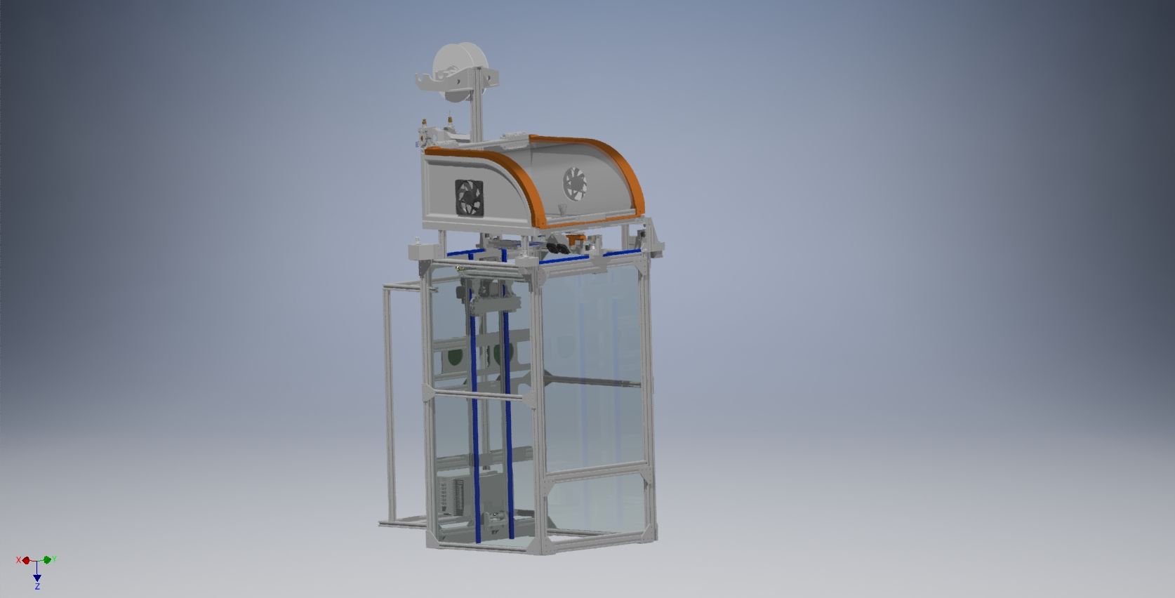
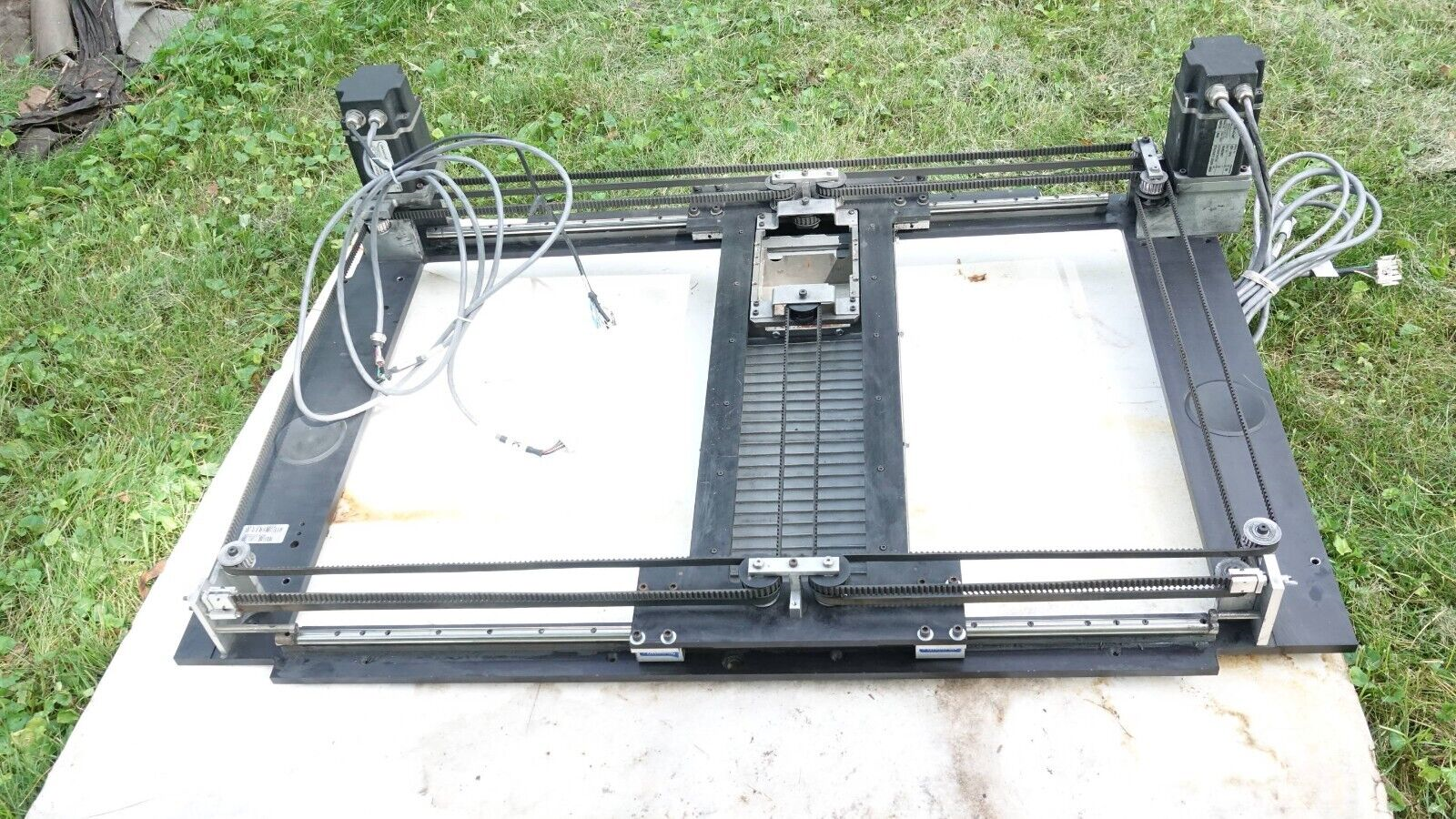
Playing around. I've done double gantry rails before, was super rigid. Thoughts?
It's a 6x6.

-
@gnydick Honestly I think the combination of the aluminum frame assembly, double gantry rails for the X and Y axes, and the associated belt pathing is unnecessarily complicated and would be really tough to assemble (and maintain).
I think sticking to a single linear rail profile of a beefier profile for the Y-axis is a better option than the double stack you have shown. I'm thinking something greater than a rail width of 15mm (vs the 9mm or even 12mm thats common for DIY printer builds).
For the X axis segment, I also thing the double stacked system is overly complicated. You could do a similar setup as my below image where two rails are arrayed horizontally rather than vertically, but if your goal is tool changing, this might not be feasible.
I think the aluminum profile can be a really good option for vertical members of the build, but I think for a CoreXY (or really any sort of motion system where the bed does NOT move horizontally) a large, flat surface with limited vertical beams gives you the best chance to have a quality mechanical layout.
-
@sebkritikel I know what you mean. If I was to go this route, each stacks would be joined in a block. Otherwise there'd be a lot of potential for problems.
-
@gnydick I use double X rails but side by side, just so that I can sling my heavy, multi input hot ends between the rails. But the downside is that I lose potential Y travel. I'm working on a design which will have just a single input hot end - probably a Bondtech LGX Ace with Slice Engineering Mosquito but that will just use a single rail - probably 2040 on it's side so the 20 will be in the Y direction and the 40 being the depth. That should give me the Y travel I'd like whilst being stiff enough.
-
I'm also not a big fan of doubling up the rails. If you are contemplating doing it, you need to think about how you'll keep both rails perfectly aligned. If they are slightly off, they can easily jam instead of rolling smoothly. You'll certainly get experience with this effect when you work to align just two Y-rails. If you do pursue this, mounting both on the same piece of material is a good solution. That way, the pair of rails can be aligned one time and should stay that way.
I also recommend thinking hard about what forces those additional rails are counteracting. Usually, this means some mass that's located away from the sliding block, or belts that are connected far from the sliding block. These can put torques on the block during a fast stop or start and those torques can lead to undesired movement of the nozzle. Does the added rail counteract the torque well? Why is there so much torque in the first place? Why is this helping?
My personal design direction in this case was to design the belt fastenings to be as close to the sliding blocks as possible and to try to keep the mass of the print head also as close to the sliding block as possible. If the moment arm is short the torque will be lower.
-
@mikeabuilder yep. pretty much the toolhead is not going to be centered because it's a tool changer.