8mm Cast Tool Plate Design Advice
-
@dc42, the Jubilee has it's z sensor on the carriage and the bed map is done without a tool head mounted. I doubt that it the weight is much more than 50 gr. Now once a tool head is mounted, I can see a bit of deflection even though the gantry on the Jubilee seems very sturdy.
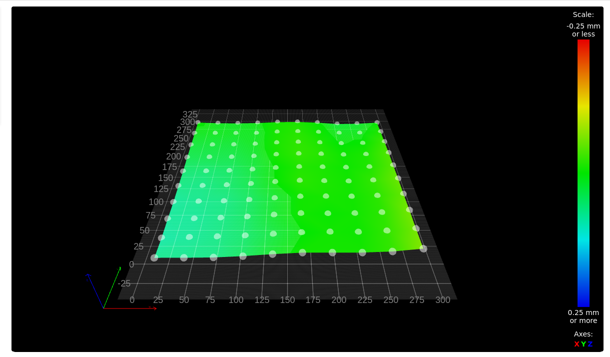
As it turned out, loosening all the screws on the crossbar and tightening them ever so carefully from the center out got me a much improved picture. At the back things are out +- 0.02 mm and at the front it varies between +0.072 and - 0.073 mm. Very much improved. I am gobsmacked that the mounting screws of the x rail could cause so much distortion ... I guess when you are dealing with tiny dimensions, normal ways of thinking do not apply.Next I will go back to my original build plate which is not a cast tooling plate and see how that looks. I will run it both hot and cold, just for the heck of it.
-
@jens55 said in 8mm Cast Tool Plate Design Advice:
I am gobsmacked that the mounting screws of the x rail could cause so much distortion ...
Maybe there was a different room temp when you tightened them the 1st time?
If possible, I leave one end of the crossbar floating to be able to compensate fluctuations. -
Thanks all for the advice, this is very timely... I'm about to rebuild my TronXY as a VzBoT, but with a Jubilee-style kinematic bed.
Ian
-
Okay, thank you.
Pertinax, just looked this up. It's apparently a Trade Name for FR-2, or in other-words a PCB without the copper layer.
I do remember seeing a video from Makers Muse a while back and he recommend FR-2 or something similar.Regarding using these stick-on magnetic sheets. I was under the impression that these could cause undulations, and this was the reasoning behind milling pockets on the underside of the tool plate for neodymium magnets.
I don't know weather to go with neodymium magnets now or not. You've got to get the correct strength in force, at the correct depth, and have enough of them strategically placed.
@droftarts said in 8mm Cast Tool Plate Design Advice:
I'm about to rebuild my TronXY as a VzBoT, but with a Jubilee-style kinematic bed
Do you have any idea on what magnets are used on the jubilee bed and at what depth?
@mrehorstdmd said in 8mm Cast Tool Plate Design Advice:
everything sticks to PEI
Do you not bother with any adhesives, and would adhesives not help to save the PEI sheet?
I know I'm going to do as @deckingman has previously advised and drill a 3mm hole from one edge, as deep as I can towards the centre for the thermistor and also screw a TCO to the edge as well.
-
@Dizzwold I don't use any adhesives on the PEI at all. Everything I print with sticks. I sometimes have trouble getting larger TPU prints to let go. That's where a few drops of IPA help the print to release. I use a very sharp Olfa scraper to pry prints up. The PEI surface gets scratched up a bit, so I occasionally smooth it with a melamine sponge and frequently clean it at room temperature with IPA. The PEI that's on the bed now was installed when I built the machine, so 4 or 5 years ago. It lasts. The adhesive that holds it down is good for about 2 years, then it let's go of the PEI. So you just clean off the bed plate and the PEI and reassemble with a fresh sheet of adhesive. Then just a tram check/set and z=0 set and you're done. I suspect that sealing the edges of the PEI/adhesive with silicone would prevent the adhesive from letting go of the PEI. I'll be replacing the adhesive on my printer in the next week or two and will try it and see.
If you have the heater secured to the bed plate in a reliable mechanical way, you can mount the TCO on the plate. But if you use adhesive to mount it on the underside of the bed plate, the TCO should be fastened to the heater, not the bed plate. If the adhesive fails and the heater drops away from the bed plate, the plate mounted TCO won't do its job. I mounted the TCO on the heater in my printer using high temperature silicone, the same stuff I used to mount the heater on the bed plate.
-
@Dizzwold said in 8mm Cast Tool Plate Design Advice:
I don't know weather to go with neodymium magnets now or not. You've got to get the correct strength in force, at the correct depth, and have enough of them strategically placed.
I used 6mm plain ordinary aluminium sheet (I didn't specify grade to my supplier, they supplied 5083 grade, apparently). It's not machined or cast or flatted, with a magnetic-held spring steel plate. It's flat enough for me:
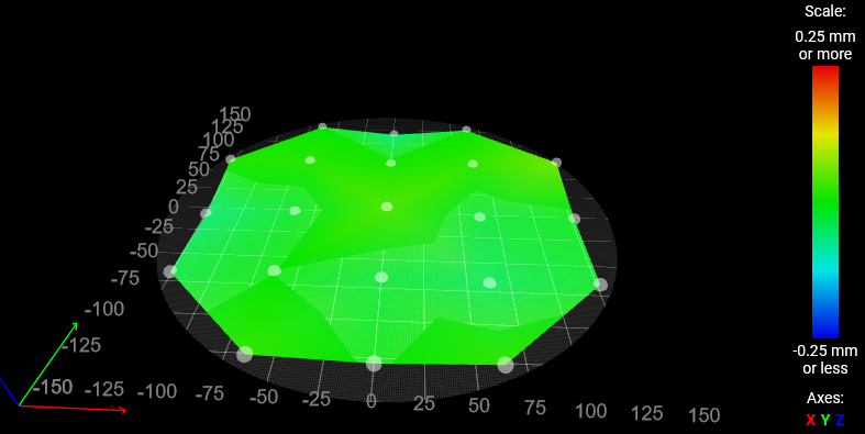
The print bed plate is 'floating' on cork insulation. That is, there's an aluminium plate bolted down on the printer frame (actually, it has a thin PETG isolator to limit thermal conduction), then a stack of cork tiles with the print bed plate on top. The whole stack is lightly (ie, snug but not torqued down hard) clamped together with 3mm bolts at three points, but they are relatively flexible so I don't expect them to restrict plate expansion. I've never detected any bowing or warping as it heats.

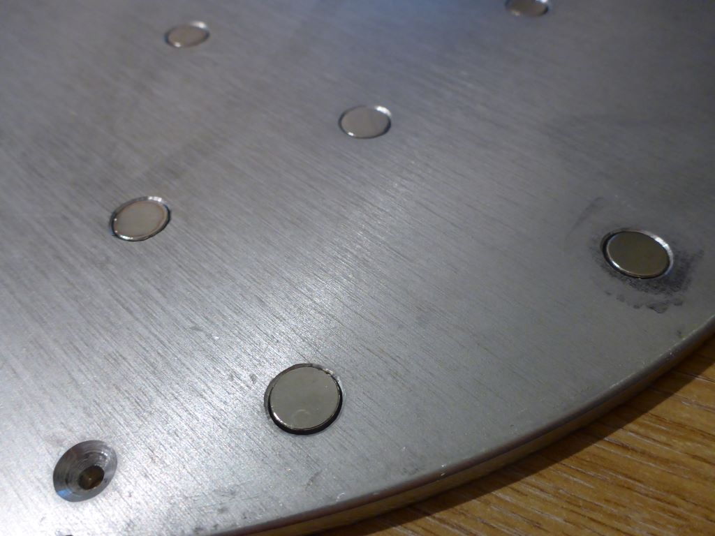
I only decided to do magnets after getting the plate cut, so the magnet holes are drilled by me with a hand-held electric drill, straight through (i.e. giving a hole all the way through the plate). That means the magnets are in (pretty much) direct contact with the steel plate. Top surface:
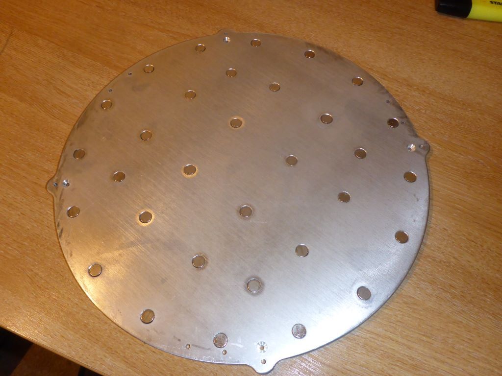
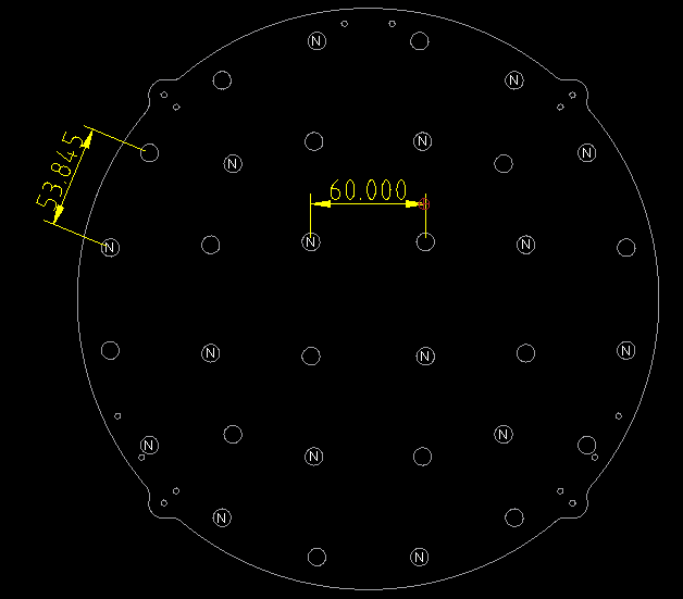
Magnets are 9mm dia, 3mm thick Samarium Cobalt, nominally 1kg pull (when in contact with a large steel plate 3mm thick). There are 32 magnets on a 300mm diameter bed. The central ones are spaced at 60mm. The layout and number was decided by eye and some playing around with different layouts held by sticky tape before drilling the plate. They alternate in pole orientation:
They are glued in place with a high temperature epoxy. Specifically MG Chemicals 8329TFS which is claimed good for 150C service indefinitely, lowish viscosity (similar to 'ordinary' araldite - flows, but slowly) so it fills up the holes, long pot life (4 hours) so I wasn't rushed.
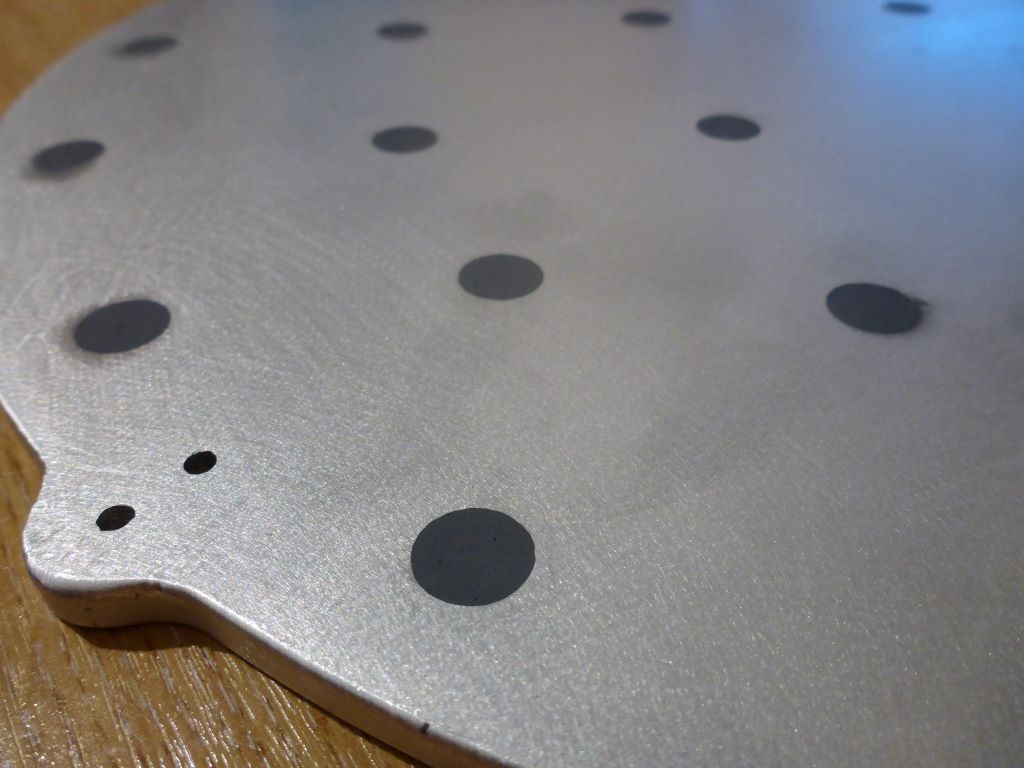
tds-8329tfs-2parts.pdfIt needs a heated cure. I just clamped the plate face-down on a glass sheet, dropped magnets in holes (they are a very loose fit - holes are probably 0.5 to 1mm larger diameter than the magnets), filled up the hole behind the magnet with epoxy, put the whole assembly in my (ordinary kitchen domestic) oven to cure. I gave it 90 minutes at 80C and then switched oven off and left it to cool in situ. This has a high shrinkage (even for an epoxy). I over-filled the holes and sanded down the back afterwards so the heater mat could be stuck on.
Bottom:
(Side note on oven - I ran some test cycles with thermocouples in it - my oven does massive overshoot on the first cycle, then much smaller variations subsequently, so I preheated the oven to avoid the massive overshoot.)
In service, one magnet has come loose (almost immediately - within a couple of weeks), leaving the epoxy in place. I refixed it with a drip or two of loctite 648 and it has stayed in place since.
I use a 0.5mm spring steel plate with PEI.
If I did it again I'd want a little more grip - I've never had a problem, but the plate doesn't grip as well as on my Prusa i3. I'd ideally go for about 50% more grip, so either close magnets up to 40mm or more powerful magnets. Obviously, if your magnets are actually set away from the surface, you'd need more powerfual and/or closer magnets too.
Note that this bed does grip a Prusa spring steel sheet as strongly as the Prusa printer - the Prusa plates are thicker, and possibly a more magnetic grade of steel.
Do you not bother with any adhesives, and would adhesives not help to save the PEI sheet?
I never put any adhesives on the PEI. For PETG I clean it first with 'Windowlene' (UK clear bluish spray not the pink cream), for PLA I wipe over with isopropanol. For flexibles I would use masking tape on the bed because otherwise it sticks too well and I can't get the print off without tearing it (but that's actually experience from a different printer - this one is a long bowden and I haven't tried soft flexibles) . The only problem I've had was with some other filament type I've forgotten, which bonded too tightly and pulled a lump of PEI out of the middle of the surface (so I replaced the sheet).
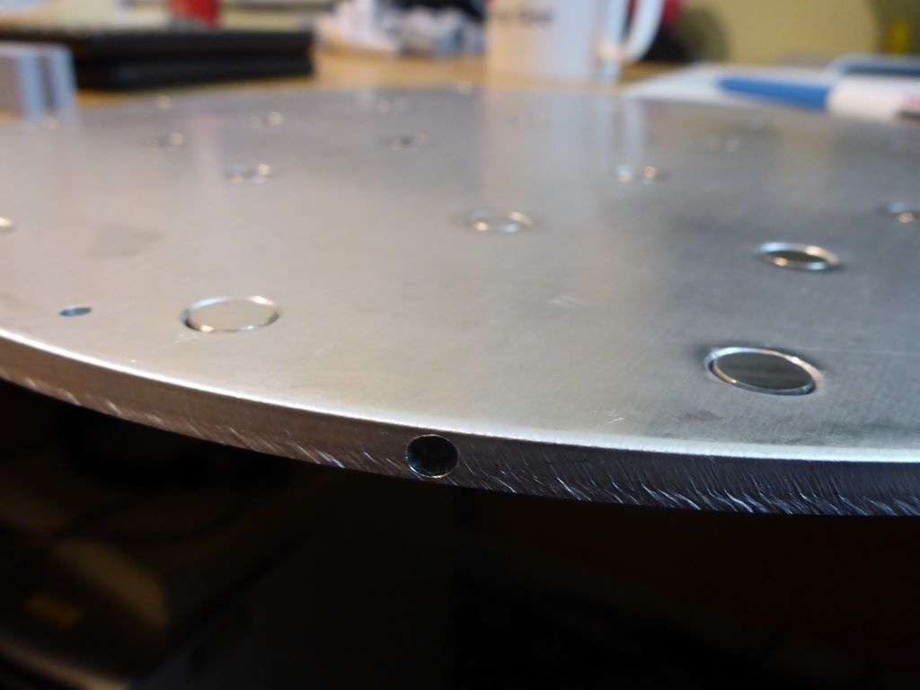
I know I'm going to do as @deckingman has previously advised and drill a 3mm hole from one edge, as deep as I can towards the centre for the thermistor and also screw a TCO to the edge as well.
Works well for me, though mine's a 4mm hole in a 6mm plate. Hole is about 40mm deep, again just drilled by hand-held electric drill, but slowly and with a printed guide / jig:
-
@mrehorstdmd said in 8mm Cast Tool Plate Design Advice:
the TCO should be fastened to the heater, not the bed plate. If the adhesive fails and the heater drops away from the bed plate, the plate mounted TCO won't do its job.
Wow, that I missed. That could've be a very serious mistake in a worse case scenario. Thank you for correcting me with this.
@achrn
What can I say other than Thank You. Very informative and gives me a greater idea of where I'm possibly going with this.
A great blueprint to work from -
@achrn @mrehorstdmd @droftarts @o_lampe @jens55 @dc42 @deckingman @Lo-Fi @jay_s_uk
Hi Guys,
Right then after all this time the tool plate is in the machine shop.
For the moment I've decided not use magnets and go with the full 1 x 400 x 400mm PEI sheet.
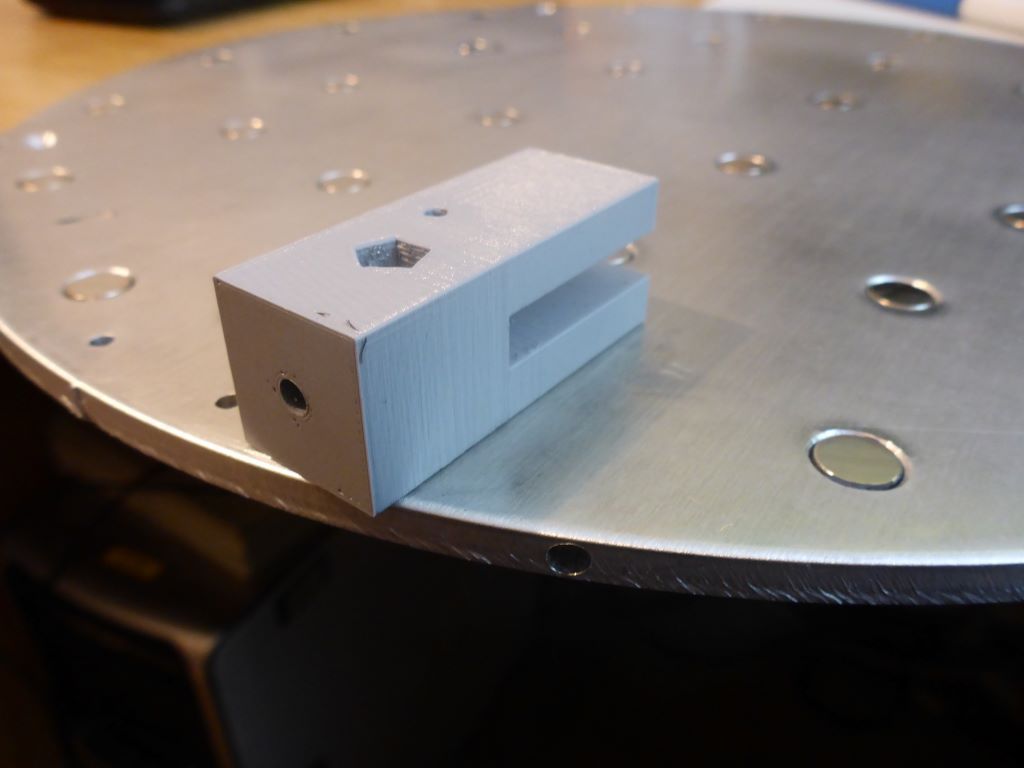
The bed will be fastened to the bed frame using 4 x 25mm M4 PEEK screws from High Performance Polymers, that will screw 4mm into the tool plate.
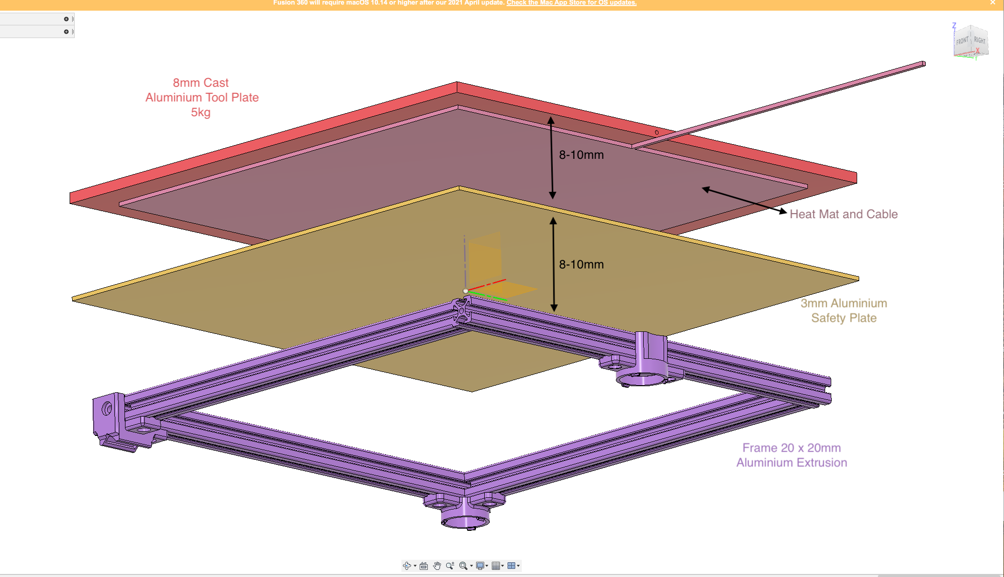
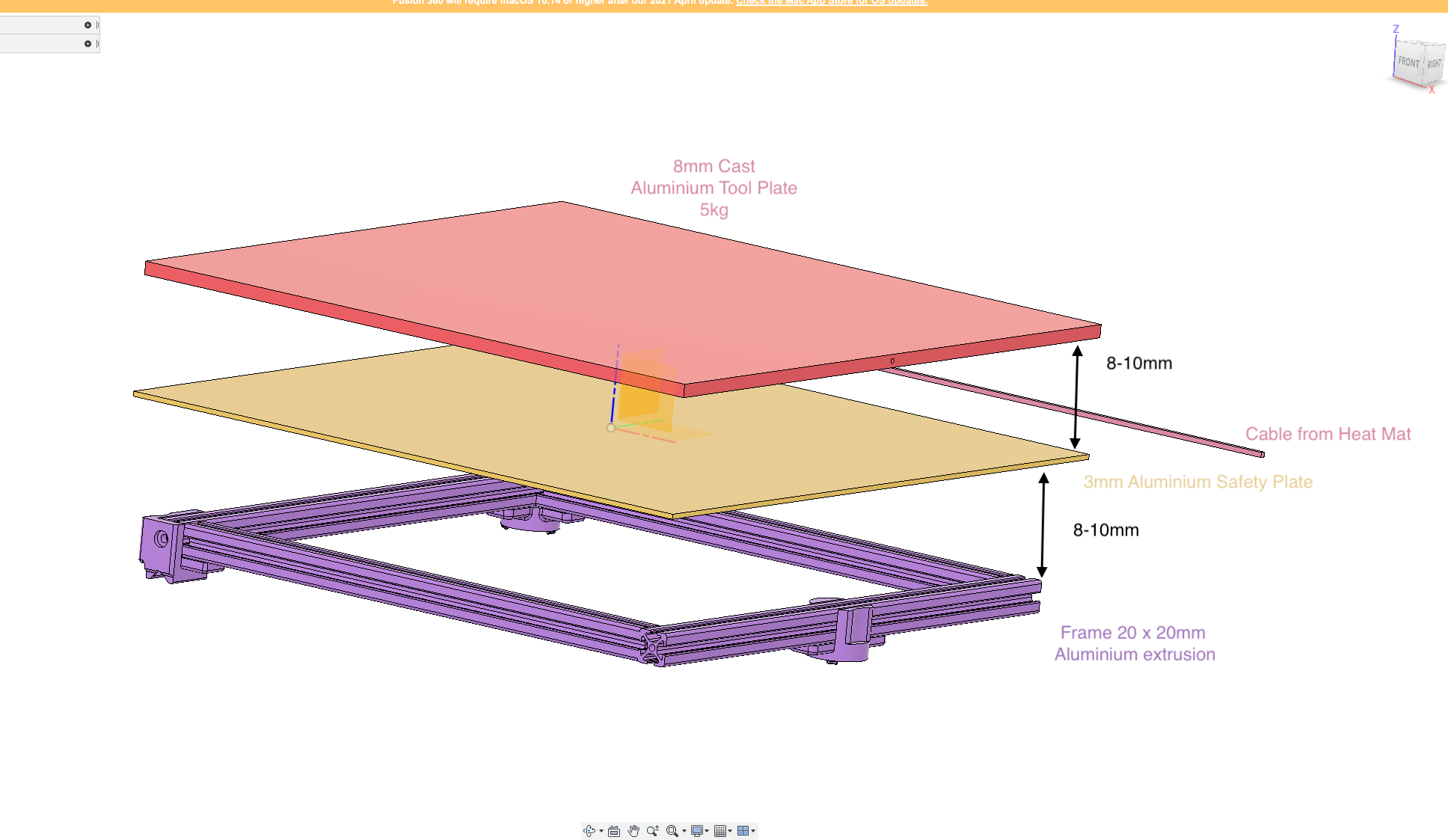
There will be a 3mm aluminium sheet held in place on the underside 'sandwiched' between the tool plate/heat mat and the bed frame, approximately 6mm under the silicone heat mat, to act as a safety feature should the high temp silicone adhesive fail. This silicone will also be used to hold a TCO in place on top of the heat mat.Please ignore the 8mm distance used in the following images. These where drawn more for illustration purposes.
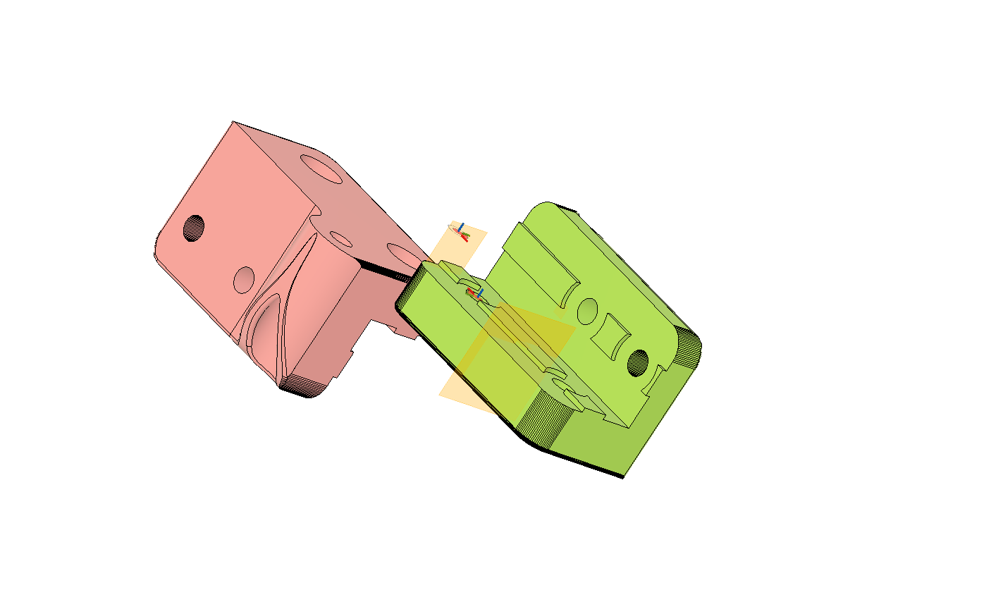
These are the brackets to hold the bed to the frame;
For the bed's temp sensor there will be 3mm wide channel milled out from one edge to the centre 3mm deep, to allow for replacements when needed.
Now to my question;
I'm looking for recommendations for an adhesive to bond the PEI sheet to the tool plate. I would prefer to avoid epoxies if possible due to if at any point the adhesive does fail, I'll still be able to salvage the tool plate. I also appreciate this may not be possible.
@achrn mentioned the MG Chemicals 8329TFS for the magnets but is an epoxy, and @mrehorstdmd mentioned the 3M 468MP giving up after a few years, although he did suggest placing mastic around the edges may increase it's longevity?
I do have a sheet of 3M 468MP, maybe this this the way to go as it can be replaced, with some work?I'd be grateful for your thoughts, although if any are regarding the tool plate this may already be machined. Hey-ho.
Dizzwold
-
@Dizzwold I think the 468MP is probably the way to go even though it may require replacement every couple years. I suspect longevity is partially a function of the temperature at which you're printing. The thickness of the 468MP sheet seems well controlled, so if the plate under the PEI is flat, the surface of the PEI will be, too, as long as you don't trap any big air bubbles under it. When it is time to replace the adhesive, you'll be cleaning it off the aluminum, not the PEI. I don't remember what I used to do it last time- I think it was paint stripper that worked very quickly and easily.
I am about to replace the adhesive in UMMD because the PEI is starting to lift again -it's been about 3 years since I changed it, IRIC. I used to print a lot of ABS with the bed at 100C but in the last year or two I've mostly been printing PETG at 70C.
-
Thank you for your advice.
I suppose 3 years is good mileage considering.
Regarding removing the 3M 468MP, do not try IPA. The heater I purchased came with this already fitted by mistake, so I first tried IPA. What a horrible gooey mess. I resulted in a scrapper and rubbing with my fingers. It took a few hours, but had to be done
For fitting my heater mat and PEI, I've purchased a small roller just for this job;
https://www.amazon.co.uk/gp/product/B094VCBCNW/ref=ppx_yo_dt_b_search_asin_title?ie=UTF8&psc=1Dizzwold.