Hollow shaft extruder
-
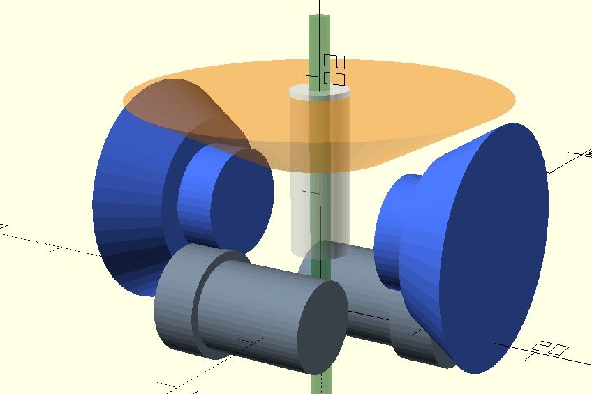
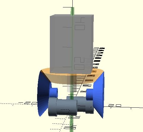
Based on @droftarts idea, I sketched a extruder drivetrain which requires a stepper motor with hollow shaft where the filament passes through.
It's just a raw concept. The gear ratio should be different than what is shown.
Maybe the main gear (orange) could be a planetary gear with additionally beveled orbit-gear?The dark grey parts are the small dual drive gears we know from Bondtech.
Have a nice sunday
Olaf//edit I think the title fits better now, since the thread drifts toward threading extruders which also require a hollow shaft stepper
-
-
-
I worked on something similar few years ago, but the filament path went through the bevel gears and was driven by left hand and right hand threaded nuts. See: https://drmrehorst.blogspot.com/2021/08/an-old-project-snakebite-extruder.html
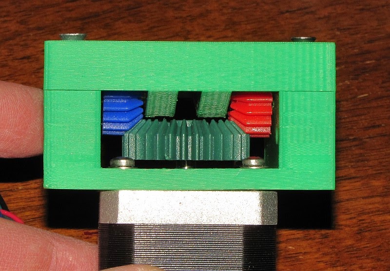
In the photo the two small bevel gears (blue and red) are mounted on 5 mm brass tubes with ball bearings, and the filament drive nuts are located on the ends of the tubes.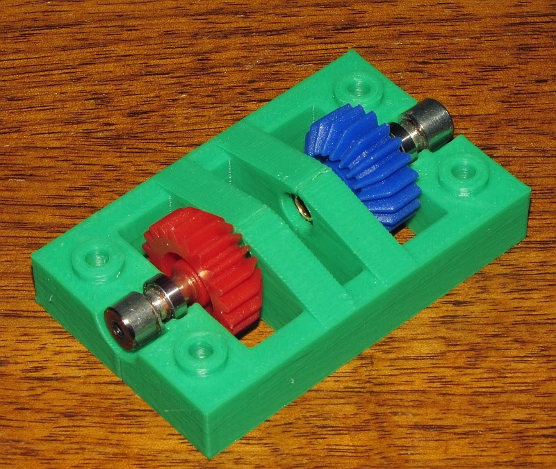
It was for 3mm filament- the drive nuts cut/rolled threads into the filament. It had several problems and I eventually abandoned it, but not before printing with it a few times.
Others have been making threading extruders. Here's one that looks like it works pretty well- a hollow motor shaft rotates a part that holds 3 ball bearings at a slight angle, with bearing flanges ground sharp so they cut into the filament. https://www.youtube.com/watch?v=YTADdWiFQnI
More here: https://reprap.org/forum/read.php?424,883786
Your concept is interesting, but I think it's going to be hard to mount those blue bevel gears and have them spin nicely with the filament path going right down the middle. Not much space for bearings in there... Then there's the dual drive problem that creates print artifacts (https://www.youtube.com/watch?v=32dTLRNIYmw).
-
@tecno I thought the same. The round Nema14 steppers we know from Orbiter & Co all come with a pressfit gear on a smaller shaft.
-
@tecno I find Nanotec a good company, so this may be interesting (second model)
https://en.nanotec.com/products/1269-hollow-shaft-motors -
Send a question to Jason at LDO motors and see if they can help.
-
@mrehorstdmd said in straight drive train extruder (needs renaming):
I think it's going to be hard to mount those blue bevel gears and have them spin nicely with the filament path going right down the middle. Not much space for bearings in there.
One of the dual drive gears runs on barrel bearings and a fixed 3mm shaft. IMHO there is enough room beween stepper shaft and the blue gears to guide the shafts.
-
@o_lampe said in straight drive train extruder (needs renaming):
Based on @droftarts idea
Oh dear, what have I started?! I was sitting waiting for my son at gymnastics when I thought of it. I imagined a relatively small bevel gear (the orange one) on the motor, and the first hobbed insert being drive directly off a large bevel gear (just one of the blue ones), a la Sherpa. This would give a high gear ratio, so a smaller stepper could be used, and the hobbed insert would be further from the exit of the motor shaft. With a 3mm (or possibly larger) hollow shaft, and the hobbed insert further from the motor, I'd have thought (as I sat there, with just the visualisation in my brain) there would be enough space to accommodate the small bend from the end of the motor shaft to the hobbed insert. The motor would need to be mounted at slight angle to the hobbed insert contact point.
A bend in the filament path isn't ideal, but I couldn't see a way of getting the filament path straight without the use of offset bevel gears, aka hypoid gears, which would be expensive to produce. Though 3D printed hypoid gears are a possibility!
Ian
-
@mrehorstdmd said in straight drive train extruder (needs renaming):
More here: https://reprap.org/forum/read.php?424,883786
After reading the SchnekenStruder thread, I think the cutting edge archimedes screw approach is much better. The only thing I don't like is grinding the edge manually.
I'm tempted to give it a try, if I can find (*) his NEMA11 pancake weighting only 28grams. The carrier for the bearing could be made of ABS-like resin.
Then designing an adapter that fits the smart effector....//edit it's this one, but I haven't found it in EU yet.... probably not, since the linked stepper only has a 3mm shaft. impossible to drill a 2mm hole through it?
//edit2 next best motor I found weights 60grams and has a 5mm shaft. It's similar to those used for orbiters, but without the pressfitted gear.
-
@o_lampe there is a Nema 8 here https://www.reichelt.de/hohlwellen-schrittmotor-nema-08-1-8-0-6-a-3-9-v-nema08-05hs-p335320.html?PROVID=2788&gclid=Cj0KCQjwwISlBhD6ARIsAESAmp5SVBd28tYQEtsDZDv-4GQtwyN0WT3fD8lBi6a7V1rBr5Z6D26vTaUaAkYVEALw_wcB
I don't think you can bore a hore through the steel shaft. Possible would be to disassemble the stepper and replace the shaft. Then you could use aluminium instead of steel, this spares weight (but I don't know whether the stepper's magnets need the steel as core).
-
@JoergS5 Good find! The actual weight is nowhere stated, but they mention package weight of 67grams..
Drilling through the shaft is mentioned a few times in the Schnekenstruder thread. Usually the shaft already has a center-drill and they are not hardened. -
@o_lampe I see no problem to bore the shaft, but disassembled from the stepper and using a lathe, boring half way from both sides. Rotating the shaft and using the drill non-rotating. With good cooling.
I have a lathe, I could try it for you, but I need multiple shafts because the first tries will probably fail *). 8mm would be much easier than 5 mm.
*) thinking about it, this doesn't need to be a stepper shaft. I have enough steel shafts...
Another idea, buy a normal nema 17 with hollow shaft and exchange the shafts
with a light stepper. -
@JoergS5 Another idea - clamp the motor in a drill dress press then rotate the shaft by driving the motor against a non-rotating drill bit
") (That wasn't really a serious idea but it would save disassembling the motor ..........).
(That wasn't really a serious idea but it would save disassembling the motor ..........). -
Hollow shaft stepper motors are commonly used in open source pick-and-place machines, with the suction to pick up the part fed through the shaft. You may be able to find out more about hollow shaft motors by asking at https://groups.google.com/g/openpnp.
-
@deckingman Let's see if a rotary axis limited to 2^31 angle degrees will be enough to drill through 13mm steel
")
-
@JoergS5 Don't waste your time with these experiments.
I disassembled a N17 pancake and the shaft is only pressfit into the rotor. Easy job to drill it hollow with a lathe. The hole doesn't have to be super centric. 2.5mm will do for sure. -
I played around with the beveled gear design and tried to figure out what gear ratio I could achieve.
The BMG dual drive gears are a real spoilsport, because the distance between the hobbed gear and the spur gear doubles up when mounted as shown.
The blue bevel gears can't be much larger, and the 2nd stage straight gear much smaller.
The estimated teethcount now is:
orange gear 64T
blue bevel 48T
blue spur 12T
BMG spur 17TThat sums up to a gear ratio of 1:4, that's less than any other geared extruder has.
 (unless I miscalculated, which is possible)
Q: why is the gap between hobbed and spur gear so big? Isn't there a better way to make them?
-
@o_lampe I was thinking more along the lines of the image below, using a hypoid gear.
The gear ratio is about 2:1. There's just about enough space between the larger gear and the driven hobbed insert (about 4mm) for the second hobbed insert to be in a lever housing, like in most other extruders. But you could increase the size of the gear on the motor shaft, and reduce the size of the large gear, all the way down to 1:1 (assuming the motor is strong enough for direct drive) if you needed more space. Or increase the distance between the motor and the hobbed inserts for a higher gear ratio and smaller, lighter motor.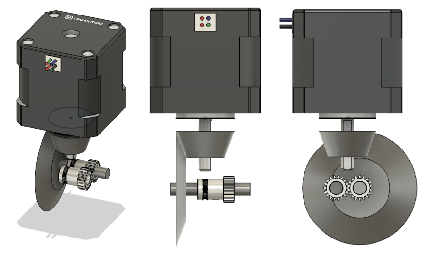
Ian
Bed-slinger - Mini5+ WiFi/1LC | RRP Fisher v1 - D2 WiFi | Polargraph - D2 WiFi | TronXY X5S - 6HC/Roto | CNC router - 6HC | Tractus3D T1250 - D2 Eth
-
Turns out my idea is pretty much the same as this one that @T3P3Tony posted about in the other thread, which looks pretty neat: https://youtu.be/eI0tD69wD18
That one uses a NEMA14. I saw pictures of it and assumed it was a NEMA17, so perhaps wouldn't be too top heavy.I think it would be worth contacting Jason at LDO to see if they have/can make any lighter pancake or round stepper motors with hollow shafts, for either the hypoid version or the Archimedes screw version.
I'd say the Archimedes screw version wins on compactness, at the expense of some concerns about the filament spinning and extrusion inconsistency, though these might be avoided with more refinement of the design and manufacturing process. Alternatively, fitting something like a filament monitor, but with a shaft encoder on it, and running the extruder in closed loop mode would help.
Ian
Bed-slinger - Mini5+ WiFi/1LC | RRP Fisher v1 - D2 WiFi | Polargraph - D2 WiFi | TronXY X5S - 6HC/Roto | CNC router - 6HC | Tractus3D T1250 - D2 Eth