Duet3D Logo Duet3D
    • Tags
    • Documentation
    • Order
    • Register
    • Login

    Duet 3 Scanning Z probe

    Scheduled Pinned Locked Moved
    General Discussion
    23
    88
    6.0k
    Loading More Posts
    • Oldest to Newest
    • Newest to Oldest
    • Most Votes
    Reply
    • Reply as topic
    Log in to reply
    This topic has been deleted. Only users with topic management privileges can see it.
    • zaptaundefined
      zapta @T3P3Tony
      last edited by zapta

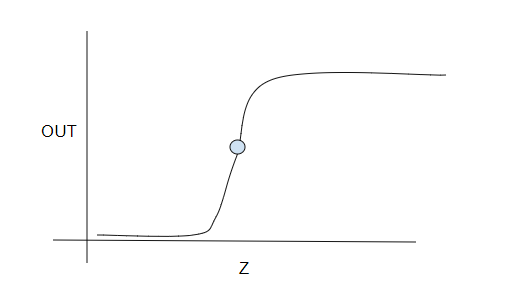
      @T3P3Tony, with the current approach, you rely of the scale calibration of the sensor, or the K1 in the linear approximation below:

      L[mm] = K0 + K1*SensorTicks

      With this approach you are K1 agonistic since the Z measurement is inherently calibrated by the Z steps which is also what the printing process uses. In other words, you relax the requirements from the sensor, and at the same time, can still mesh faster than the traditional stop-and-probe.

      Does this make sense?

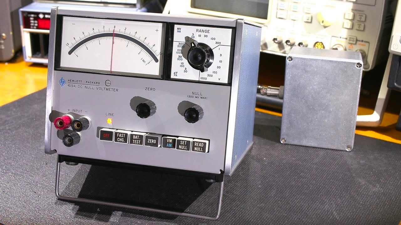
      EDIT: it's same concept as using a null meter instead of a volt meter. 99b26480-8a3f-476b-a6ed-7e1534bde4a2-image.png

      T3P3Tonyundefined 1 Reply Last reply Reply Quote 0
      • T3P3Tonyundefined
        T3P3Tony administrators @zapta
        last edited by

        @zapta I see what you mean. It would be slower than the scanning mesh on many machines (depending on Z speed) but would give the Z positions where the sensor reads the same all over the bed. I still don't think it will necessarily be any more accurate though.

        www.duet3d.com

        zaptaundefined 1 Reply Last reply Reply Quote 1
        • zaptaundefined
          zapta @T3P3Tony
          last edited by

          @T3P3Tony, I see.

          I am trying to find a way to speed up touch sensors such as BL Touch but this approach should apply also to other sensors types. My hypothesis is that if instead of a binary state they provide a small hysteresis-free continuous region around a known point, the meshing can be speed up significantly since it requires only minor Z adjustments during the scan to tack that point. Not much different from the mesh compensation during the actual printing.

          Will see how it goes.

          d16a5d72-5269-4d8f-ba08-5ada3002f8e3-image.png

          1 Reply Last reply Reply Quote 0
          • CR3Dundefined
            CR3D
            last edited by

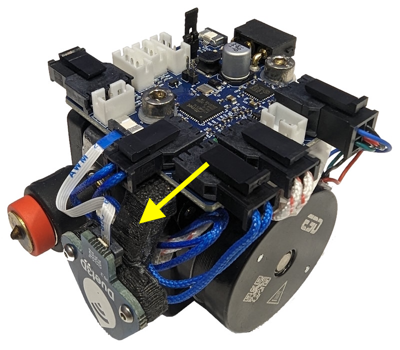
            I want to setup a Scanning Tool for our printers but can not find a wiring schematic in the documentation

            cc1a6515-d206-4c20-a0fb-862199c1fb32-image.png

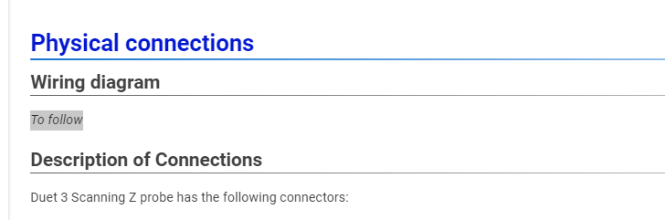
            Can you tell me how to connect pls?

            PXL_20240116_150402685.jpg

            Thank you in advance

            Christian from CR-3D
            Homepage:
            www.cr-3d.de

            Facebook:
            https://www.facebook.com/cr3d.official

            Our Discord Server
            https://discord.gg/SxRaPNuRdA

            Thingiverse Profile:
            https://www.thingiverse.com/cr-3d_official/about

            oliofundefined bricorundefined 2 Replies Last reply Reply Quote 0
            • oliofundefined
              oliof @CR3D
              last edited by oliof

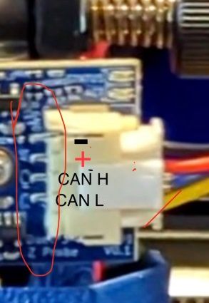
              @CR3D the PCB silkscreen points out what the pins are, I can see GND to the left, and C_L (CAN low) and C_H (CAN high) to the right. Second from the left is VCC then, this tracks with the connection description on the documentation page https://docs.duet3d.com/en/Duet3D_hardware/Duet_3_family/Duet_3_Scanning_Z_Probe#description-of-connections

              The source for 5V depends on the board you use, on the Duet 3 mini 5+ I would choose 5V and GND from IO 4 due to proximity to the CAN header.

              <>RatRig V-Minion Fly Super5Pro RRF<> V-Core 3.1 IDEX k*****r <> RatRig V-Minion SKR 2 Marlin<>

              1 Reply Last reply Reply Quote 1
              • bricorundefined
                bricor @CR3D
                last edited by bricor

                @CR3D

                Disregard this post
                see later post
                Wrong board version

                SZP-Pic.jpg

                droftartsundefined 1 Reply Last reply Reply Quote 0
                • droftartsundefined
                  droftarts administrators @bricor
                  last edited by droftarts

                  @bricor That is a V0.1 development board (see PCB bottom right corner). The silkscreen has the CAN_H and CAN_L the other way around.

                  @CR3D The V1.0 boards are:
                  GND - 5V - CAN_L - CAN_H
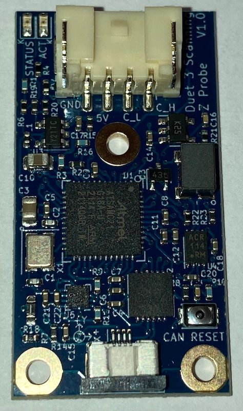
                  1705424743223.jpg

                  Ian

                  Bed-slinger - Mini5+ WiFi/1LC | RRP Fisher v1 - D2 WiFi | Polargraph - D2 WiFi | TronXY X5S - 6HC/Roto | CNC router - 6HC | Tractus3D T1250 - D2 Eth

                  bricorundefined 1 Reply Last reply Reply Quote 0
                  • bricorundefined
                    bricor @droftarts
                    last edited by

                    @droftarts
                    Thank you for the correction. I grabbed the pic from the current doc.

                    droftartsundefined 1 Reply Last reply Reply Quote 0
                    • droftartsundefined
                      droftarts administrators @bricor
                      last edited by droftarts

                      @bricor I know, I was going to do the same thing until I noticed it was different! So I took a picture of the one I had on my desk that I received earlier this week. @T3P3Tony will put up a proper wiring diagram soon, hopefully.

                      Edit: I've updated the documentation with the above picture: https://docs.duet3d.com/en/Duet3D_hardware/Duet_3_family/Duet_3_Scanning_Z_Probe#physical-connections

                      Ian

                      Bed-slinger - Mini5+ WiFi/1LC | RRP Fisher v1 - D2 WiFi | Polargraph - D2 WiFi | TronXY X5S - 6HC/Roto | CNC router - 6HC | Tractus3D T1250 - D2 Eth

                      CR3Dundefined 1 Reply Last reply Reply Quote 1
                      • CR3Dundefined
                        CR3D @droftarts
                        last edited by

                        Thanks to all! 🙂

                        Christian from CR-3D
                        Homepage:
                        www.cr-3d.de

                        Facebook:
                        https://www.facebook.com/cr3d.official

                        Our Discord Server
                        https://discord.gg/SxRaPNuRdA

                        Thingiverse Profile:
                        https://www.thingiverse.com/cr-3d_official/about

                        1 Reply Last reply Reply Quote 0
                        • Killercdsundefined
                          Killercds @ofliduet
                          last edited by

                          @ofliduet said in Duet 3 Scanning Z probe:

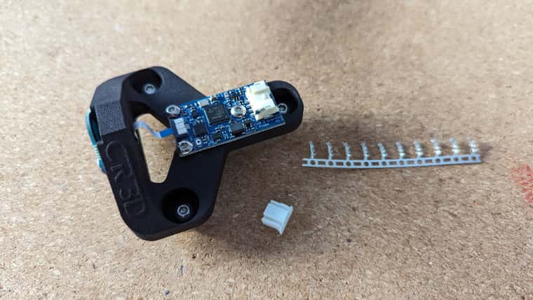
                          Is the STL / STEP for the probe holder availalbe that I see in the picture of the Revo toolboard?

                          9a2979a1-d4aa-4970-ba51-a0676c4f80d1-image.png

                          Any updates on the availability of this specific mount?
                          It seems like it's a modified version of the PCB spacer
                          I would really like to integrate it into my E3D ToolChanger setup

                          1 Reply Last reply Reply Quote 0
                          • First post
                            Last post
                          Unless otherwise noted, all forum content is licensed under CC-BY-SA