Duet3D Logo Duet3D
    • Tags
    • Documentation
    • Order
    • Register
    • Login

    Duet 3 Scanning Z probe

    Scheduled Pinned Locked Moved
    General Discussion
    23
    88
    6.0k
    Loading More Posts
    • Oldest to Newest
    • Newest to Oldest
    • Most Votes
    Reply
    • Reply as topic
    Log in to reply
    This topic has been deleted. Only users with topic management privileges can see it.
    • T3P3Tonyundefined
      T3P3Tony administrators @zapta
      last edited by

      @zapta I see what you mean. It would be slower than the scanning mesh on many machines (depending on Z speed) but would give the Z positions where the sensor reads the same all over the bed. I still don't think it will necessarily be any more accurate though.

      www.duet3d.com

      zaptaundefined 1 Reply Last reply Reply Quote 1
      • zaptaundefined
        zapta @T3P3Tony
        last edited by

        @T3P3Tony, I see.

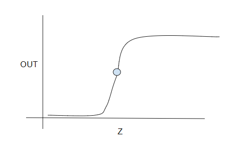
        I am trying to find a way to speed up touch sensors such as BL Touch but this approach should apply also to other sensors types. My hypothesis is that if instead of a binary state they provide a small hysteresis-free continuous region around a known point, the meshing can be speed up significantly since it requires only minor Z adjustments during the scan to tack that point. Not much different from the mesh compensation during the actual printing.

        Will see how it goes.

        d16a5d72-5269-4d8f-ba08-5ada3002f8e3-image.png

        1 Reply Last reply Reply Quote 0
        • CR3Dundefined
          CR3D
          last edited by

          I want to setup a Scanning Tool for our printers but can not find a wiring schematic in the documentation

          cc1a6515-d206-4c20-a0fb-862199c1fb32-image.png

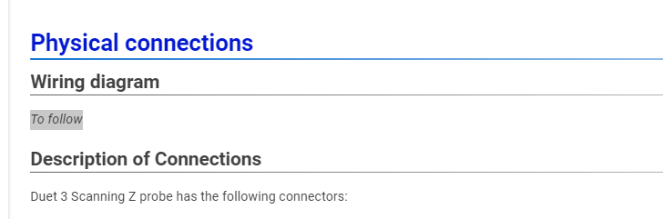
          Can you tell me how to connect pls?

          PXL_20240116_150402685.jpg

          Thank you in advance

          Christian from CR-3D
          Homepage:
          www.cr-3d.de

          Facebook:
          https://www.facebook.com/cr3d.official

          Our Discord Server
          https://discord.gg/SxRaPNuRdA

          Thingiverse Profile:
          https://www.thingiverse.com/cr-3d_official/about

          oliofundefined bricorundefined 2 Replies Last reply Reply Quote 0
          • oliofundefined
            oliof @CR3D
            last edited by oliof

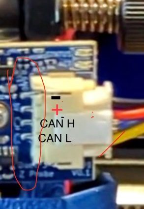
            @CR3D the PCB silkscreen points out what the pins are, I can see GND to the left, and C_L (CAN low) and C_H (CAN high) to the right. Second from the left is VCC then, this tracks with the connection description on the documentation page https://docs.duet3d.com/en/Duet3D_hardware/Duet_3_family/Duet_3_Scanning_Z_Probe#description-of-connections

            The source for 5V depends on the board you use, on the Duet 3 mini 5+ I would choose 5V and GND from IO 4 due to proximity to the CAN header.

            <>RatRig V-Minion Fly Super5Pro RRF<> V-Core 3.1 IDEX k*****r <> RatRig V-Minion SKR 2 Marlin<>

            1 Reply Last reply Reply Quote 1
            • bricorundefined
              bricor @CR3D
              last edited by bricor

              @CR3D

              Disregard this post
              see later post
              Wrong board version

              SZP-Pic.jpg

              droftartsundefined 1 Reply Last reply Reply Quote 0
              • droftartsundefined
                droftarts administrators @bricor
                last edited by droftarts

                @bricor That is a V0.1 development board (see PCB bottom right corner). The silkscreen has the CAN_H and CAN_L the other way around.

                @CR3D The V1.0 boards are:
                GND - 5V - CAN_L - CAN_H
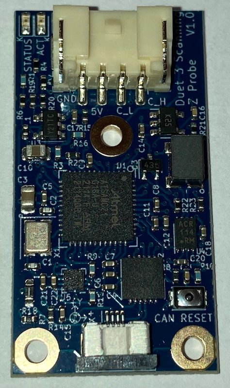
                1705424743223.jpg

                Ian

                Bed-slinger - Mini5+ WiFi/1LC | RRP Fisher v1 - D2 WiFi | Polargraph - D2 WiFi | TronXY X5S - 6HC/Roto | CNC router - 6HC | Tractus3D T1250 - D2 Eth

                bricorundefined 1 Reply Last reply Reply Quote 0
                • bricorundefined
                  bricor @droftarts
                  last edited by

                  @droftarts
                  Thank you for the correction. I grabbed the pic from the current doc.

                  droftartsundefined 1 Reply Last reply Reply Quote 0
                  • droftartsundefined
                    droftarts administrators @bricor
                    last edited by droftarts

                    @bricor I know, I was going to do the same thing until I noticed it was different! So I took a picture of the one I had on my desk that I received earlier this week. @T3P3Tony will put up a proper wiring diagram soon, hopefully.

                    Edit: I've updated the documentation with the above picture: https://docs.duet3d.com/en/Duet3D_hardware/Duet_3_family/Duet_3_Scanning_Z_Probe#physical-connections

                    Ian

                    Bed-slinger - Mini5+ WiFi/1LC | RRP Fisher v1 - D2 WiFi | Polargraph - D2 WiFi | TronXY X5S - 6HC/Roto | CNC router - 6HC | Tractus3D T1250 - D2 Eth

                    CR3Dundefined 1 Reply Last reply Reply Quote 1
                    • CR3Dundefined
                      CR3D @droftarts
                      last edited by

                      Thanks to all! 🙂

                      Christian from CR-3D
                      Homepage:
                      www.cr-3d.de

                      Facebook:
                      https://www.facebook.com/cr3d.official

                      Our Discord Server
                      https://discord.gg/SxRaPNuRdA

                      Thingiverse Profile:
                      https://www.thingiverse.com/cr-3d_official/about

                      1 Reply Last reply Reply Quote 0
                      • Killercdsundefined
                        Killercds @ofliduet
                        last edited by

                        @ofliduet said in Duet 3 Scanning Z probe:

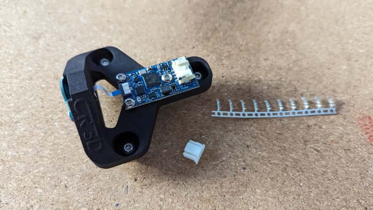
                        Is the STL / STEP for the probe holder availalbe that I see in the picture of the Revo toolboard?

                        9a2979a1-d4aa-4970-ba51-a0676c4f80d1-image.png

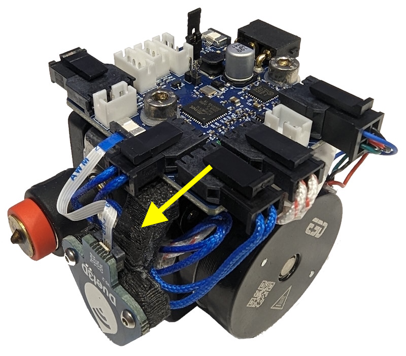
                        Any updates on the availability of this specific mount?
                        It seems like it's a modified version of the PCB spacer
                        I would really like to integrate it into my E3D ToolChanger setup

                        1 Reply Last reply Reply Quote 0
                        • First post
                          Last post
                        Unless otherwise noted, all forum content is licensed under CC-BY-SA