Duet Polargraph
-
A Polargraph is a 2D drawing machine, a vertically-mounted pen plotter with 2 motors in each top corner, and a pen suspended in a 'gondola' (or effector) in between. I've wanted to build one of these for a long time, but couldn't be bothered messing around with old-school Arduinos and RAMPS. Surely RepRapFirmware would support it? While there was the odd thread where it was suggested, there is no explicit Polargraph kinematics in RRF, so I shelved it for a long time, until @CNCModeller and @o_lampe in this thread https://forum.duet3d.com/topic/33992/control-for-maslow-style-cnc got me curious as to whether Hangprinter kinematics could actually support it. After looking at it for a bit, I thought it could...
Looking around, the Makelangelo seemed the best developed Polargraph around. I printed out the parts for the most up-to-date gondola, selected the largest MDF sheet I had under the stairs, then printed two motor mounts from this version, ordered some big bolts for weights, and put it all together with parts from the parts box and a pre-production white PCB Duet 2 WiFi, running RRF 3.4.6 (the last version to have the Hangprinter kinematics on Duet 2 WiFi/Ethernet).
After a bit of messing around with the config, and some initial tests, I realised that it was drawing curved horizontal lines towards the top of the print area. This was caused by the contact point on the motor pulley changing, the higher the pen was. To mitigate this, I added a standoff at the corner of each motor mount, that the belts touch against. This gives a more consistent 'anchor' point, as it now only wanders about 1mm in X and Y for the whole range of movement of the effector. Size is within 1mm of the A2 drawing area (420mm x 594mm, or 16.5" x 23.4" for users of freedom units), good enough for me. I added microswitch endstops at the same time, though I could probably have done homing with motor stalls. Also, tidying up the prints to remove seams dramatically improved smooth movement of the gondola. Currently, it looks like this:
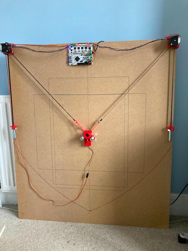
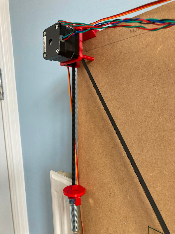
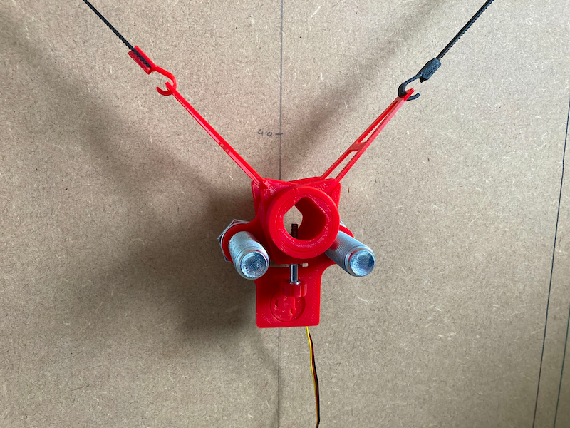
The landscape and portrait rectangles are A2 size. The lower arcs are the limit of where the pen can reach. I should have left the belts a bit longer, but these are the right size for the board, as the gondola homes at the bottom. Here's the current config.g:
; Configuration file for Duet WiFi (firmware version 3)
; executed by the firmware on start-up
;
; generated by RepRapFirmware Configuration Tool v2.1.6 on Tue Jan 14 2020 12:35:54 GMT+0000 (Greenwich Mean Time)

; General preferences
G90                                                ; send absolute coordinates...
M83                                                ; ...but relative extruder moves
M550 P"Polarian"                                  ; set printer name

; Network
M552 S1                                            ; enable network
M586 P0 S1                                         ; enable HTTP
M586 P1 S0                                         ; disable FTP
M586 P2 S0                                         ; disable Telnet

; Drives
M569 P0 S1 ; drive 0 (X motor output)
M569 P1 S1 ; drive 1 (Y motor output)
M569 P2 S1 ; drive 2 (Z motor output)
M569 P3 S1 ; drive 3 (E0 motor output)
M569 P4 S0 ; drive 4 (E1 motor output)

; For Polargraph, anchor A is dummy motor below effector, anchor B is using Z driver, anchor C is using E1 driver
; In M584 X= anchor A (dummy), Y= anchor B (Z driver), Z= anchor C (E1 driver)

M584 X0 Y2 Z4 U1 ; X=A, Y=B, Z=C and create U axis for the D dummy motor

M350 X16 Y16 Z16 U16 I1                            ; configure microstepping with interpolation
M92 X80.00 Y80.00 Z80.00 U80.00                  ; set steps per mm
M566 X300.00 Y300.00 Z300.00 U300.00                ; set maximum instantaneous speed changes (mm/min)
M203 X6000.00 Y6000.00 Z6000.00 U6000.00            ; set maximum speeds (mm/min)
M201 X3000.00 Y3000.00 Z3000.00 U3000.00                ; set accelerations (mm/s^2)
M906 X100 Y800 Z800 U100 I30                    ; set motor currents (mA) and motor idle factor in per cent
M84 S30                                            ; Set idle timeout

; Kinematics
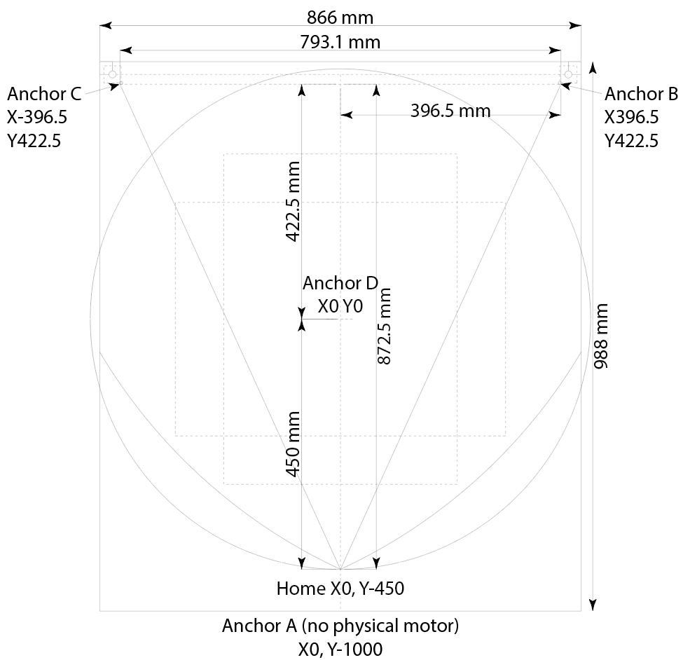
M669 K6 A0:-1000:0 B396.5:422.5:0 C-396.5:422.5:0 D0:0:1000 P450 ; configure hangprinter kinematics
;M669 K6 A396.5:-422.5:0 B396.5:422.5:0 C-396.5:422.5:0 D-396.5:-422.5:0 P450
M666 Q0.0001 R6.365:6.365:6.365:6.365 U1:1:1:1 L20:20:20:20 H20:20:20:20 J200:200:200:200

; Axis Limits
M208 S0 Z200                                                ; set maximum height
M208 S1 Z0                                                  ; set minimum height

; Endstops
M574 Y1 S1 P"zstop"                                ; configure active-high endstop for high end on X via pin xstop
M574 Z1 S1 P"e1stop"                                ; configure active-high endstop for low end on Y via pin ystop

; Tools
M563 P0 S"Pen"                                     ; define tool 0
G10 P0 X0 Y0 Z0                                    ; set tool 0 axis offsets
G10 P0 R0 S0                                       ; set initial tool 0 active and standby temperatures to 0C

; Servo
M950 S0 C"exp.heater3"

; Custom settings
M912 P0 S1.5                                       ; MCU temperature offset

; Miscellaneous
;M501                                               ; load saved parameters from non-volatile memory
M911 S11 R12 P"M913 X0 Y0" ; set voltage thresholds and actions to run on power loss
T0                                                 ; select first tool
A layout showing dimensions:
And finally, some things I've actually got it to draw! Mostly I've used the Makelangelo software, which has a good amount of features, allows for import of svg files, and a fair number of filters for pixel images. @jay_s_uk has recently put me on to DrawingBotV3, which I intend to try out too.
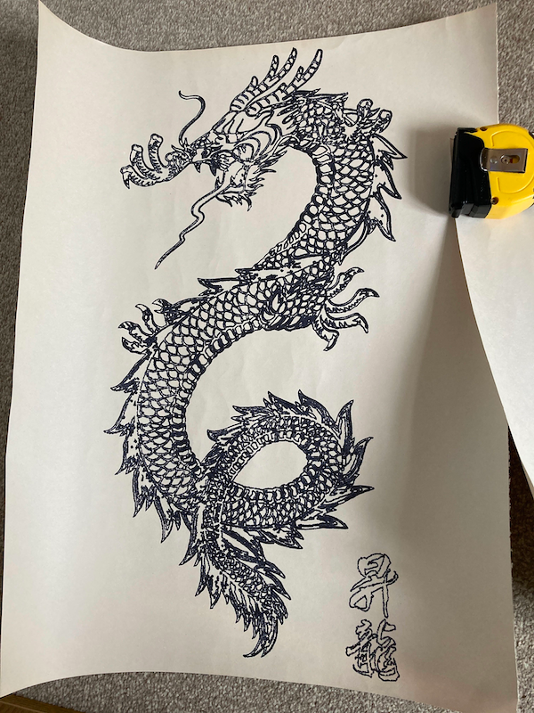
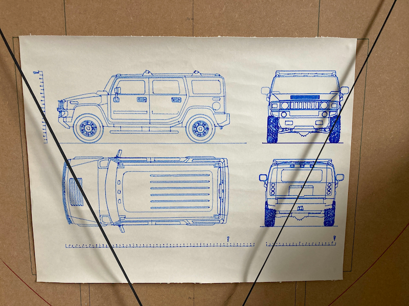
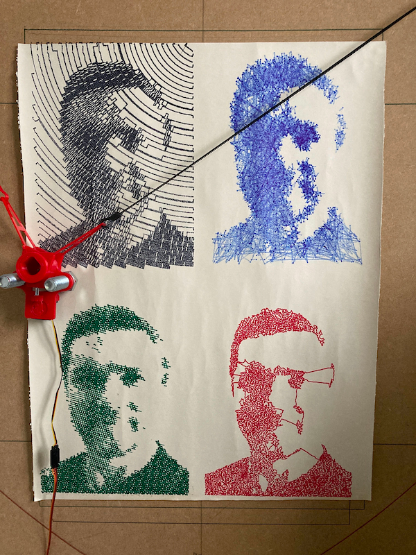
I asked @tobben on the Hangprinter Discord about the kinematics, and he thinks the four anchors that Hangprinter uses can be placed anywhere (the documentation says the D anchor needs to be over X0 Y0). This opens up the possibility of some other cable-based machines:
- Machines like the Maslow router, with a rigid rectangular frame and an anchor in each corner.
- For a vertically mounted 4-cable polargraph (which would help stabilise the effector), you could have two motors each side at the top corners, and an idler at the bottom corner each side for the lower cables. Then weights for each corner can be hung, and move up and down.
- For a roomcam/four point Hangprinter, you would have the 4 anchors on the ceiling, in the corners of the room. It wouldn't be as well constrained as a normal hangprinter, and I'd tend to have the motors in the corners, not on the effector. Or hanging off the lighting towers of a stadium, which is what they do with the Skycam, see https://en.wikipedia.org/wiki/Skycam
Feel free to ask if you have any questions, I'm happy to elaborate!
Ian
-
@droftarts nice write up. I'm looking forward to seeing some of the prints from drawingbotv3
-
@droftarts Awesome work, my hero!
So the accuracy lies in the details, like a constant angle at the motor pulley, but a varying angle at the effector. That's why my build was off the track for so much.
OTOH, I was happy with my belt tensioning system, using no weights but a BLDC motor in torque mode. Also good for horizontal use cases.In your case, I'd add rollers for the belt guides, as they might add friction and disturb smooth motion. The fish hooks look pretty flimsy, too as do the wings of the effector. But that's the original Makelangelo design.
I'm intrigued to try it again, especially now with your very helpful drawing. To know, what's what helps a lot to derive the right numbers for the kinematics.

PS: I'm currently watching lots of woodworking videos on YT and they always need a lot of time to sketch up their cutting lines and such.
A "strap-on" version of such plotter (as we discussed in the maslow thread) would be a huge help as they often have their plans in DXF format anyway. -
 undefined droftarts referenced this topic
-
@o_lampe said in Duet Polargraph:
So the accuracy lies in the details, like a constant angle at the motor pulley, but a varying angle at the effector. That's why my build was off the track for so much.
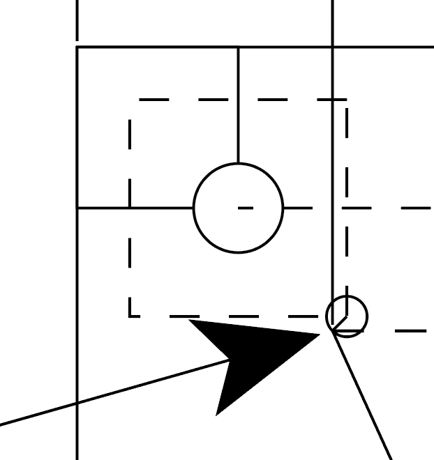
To make the triangles work, the line from the anchor point to the effector centre really needs to be as close as possible to being in a straight line. Otherwise you're going to get an error. The motor standoff that the belt runs around is only 5.8mm in diameter. I chose the point at 45° as the pivot point, which is roughly at the point the belt touches when the gondola is at the centre of the area, ie X0 Y0. As the gondola moves to the limits, the anchor point does move, but only about 0.8mm in the 'significant' direction. The 'less significant' direction error is around 1.5mm, but has less effect on the calculations, as it is the long side of the triangle.
Close up of the 'C' anchor (top left motor). The arrow points to the pivot point on the 5.8mm standoff:
I think it would be easy to 'do the math' to account for the anchor point movement, and it's possible that other firmwares already do that. I haven't looked at the Makelangelo code (it uses it's own branch of Marlin). Putting the motor centre as the initial anchor point, with the radius of the motor pulley, and the direction of rotation, it could be calculated and adjusted for.
Where you set X0 Y0, and making sure you accurately home to that point, so the anchor points are accurate, is also important.
OTOH, I was happy with my belt tensioning system, using no weights but a BLDC motor in torque mode. Also good for horizontal use cases.
That's cool. Maybe four BLDC motors in torque mode would be a better way to spool the cable/belt if you built something with a motor at each corner.
In your case, I'd add rollers for the belt guides, as they might add friction and disturb smooth motion. The fish hooks look pretty flimsy, too as do the wings of the effector. But that's the original Makelangelo design.
Adding rollers would make the diameter of the pivot point bigger, and increase the error. The back of the belt is sliding on the standoff, which is printed in PLA, so without much weight on the gondola, I think it's fine.
The effector wings are printed flat, so are actually pretty strong. The hooks are also printed with the layer lines along the hook, so should be okay. I did break one putting the belt in, but it had warped off the bed anyway, so was too tight. That did break across a layer line. Generally pretty happy with the printed parts, nothing I'd change.
Ian
-
 undefined droftarts referenced this topic
-
 undefined droftarts referenced this topic
-
@droftarts I was noticed, you've edited a post, but couldn't find any big news.
Did you add the drawings lately?THX
Olaf -
@o_lampe No, I just updated a link that I got wrong in the first post, to the motor mount. I'm updating it a little (moving it off the big board, onto a smaller bar like the original Makelangelo, to make it more portable) and fixing a couple of bits (the servo had broken loose), as I'm taking it to SMRRF in Manchester this weekend. Changing the motor mounts to make them shorter, too.
What drawings do you want?
Ian
-
@droftarts said in Duet Polargraph:
What drawings do you want?
No need for drawings, I was talking about the drawings you made with it. Didn't remember seeing the dragon before.
Good luck in Manchester
Olaf -
Polargraph Update...
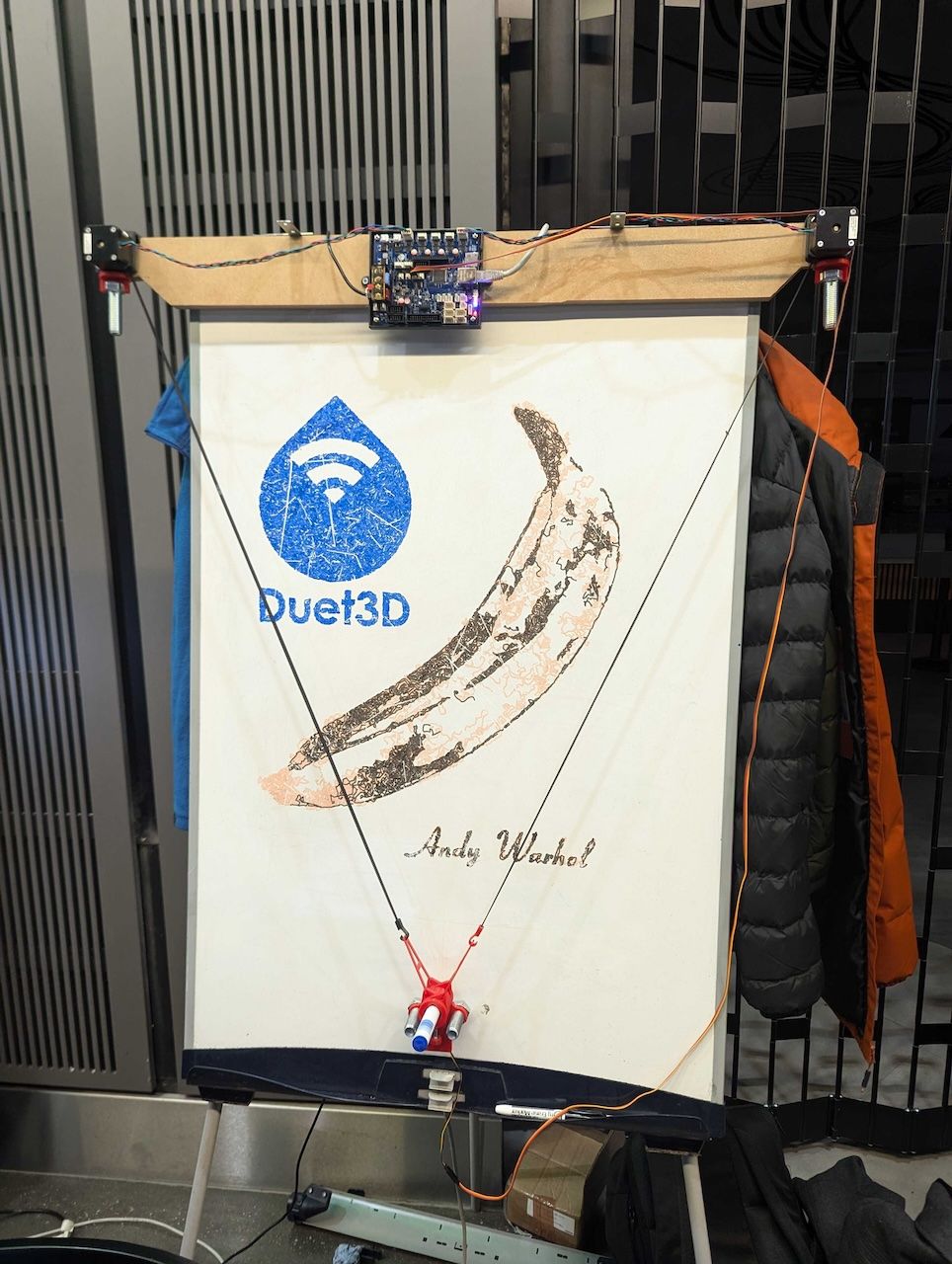
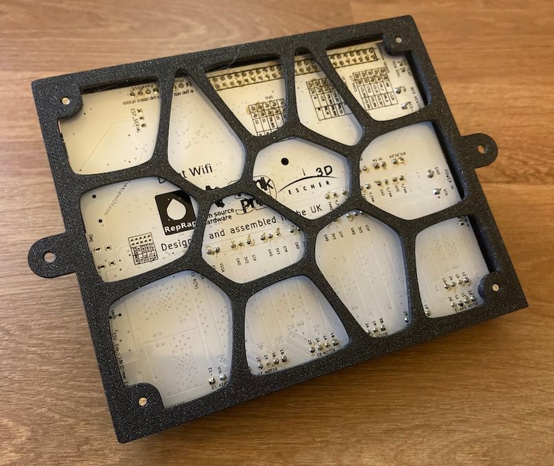
I took the Polargraph to SMRRF 2024 in Manchester last weekend. As it was mounted on a large MDF sheet, and I was travelling by train, this required a little bit of re-engineering. I re-mounted it on a strip of MDF, the same width as the original piece (so I didn't have to change the config), and updated the motor mounts so the belts hang closer to the wall, as there was now a step down from the motors to the drawing surface. I also did a nice Voronoi case for Duet boards (produced the Voronoi in Inkscape, which I spent far to long playing around with, see https://youtu.be/0fzJdGRzjf8 then extruded that in Fusion 360), but of course that was invisible as it was behind the Duet!
When I got to Manchester, @T3P3Tony insisted that I update it from the old, white PCB prototype Duet 2 WiFi, to a Duet 3 Mini 5+. This induced some headaches, as I eventually realised the comments in the config.g relating to anchor positions and motors was not correct in the original version. I have updated the config.g first post in this thread so it is now correct. I also removed the endstops, intending to make homing sensorless, but didn't get around to that, and just ended up homing manually. It was mounted on a white board, so easy to wipe off the board and draw something else. I'm sure that says something about the impermanence yet repeatability of art...
Apart from that, it ran smoothly for the weekend. It mostly drew things I'd created before, but I eventually got around to doing a couple of new things. There was a bit of an Andy Warhol/art theme (there were some impressive Hueforge prints), so I used DrawingBot to produce some of my own:
Here's the Voronoi case. Let me know if you want the stl.
Ian
-
@droftarts really fun to have it at SMRRF. Next stop pen changing?
-
@droftarts that looks fun. Please share the case.
-
@oliof said in Duet Polargraph:
Please share the case.
Here you go: Duet 3 Mini 5+ case.stl
It fits a Mini 5+ Ethernet or WiFi. I had to hack a bit out of the side around the WiFi module to get the Duet 2 WiFi to fit. Makes quite a nice bench test enclosure, though it's more of a board carrier than a full case. Doesn't use too much filament, so prints quite fast. Also mounting holes are for M3x8mm. I probably should have made the sides a tighter fit on the board, there's a 3mm gap all around between the board and side.I printed two, and put the Mini 5+ Ethernet in it that runs a demonstration closed loop linear axis, with a M23CL. Now it can sit on top of metal things without shorting out! We found out that our little server PC (that was collecting the data from the closed loop axis and displaying it in Graphana) had a metal band around the edge the hard way, fortunately no damage.
Ian
-
@T3P3Tony said in Duet Polargraph:
Next stop pen changing?
I guess the hard part of that is: keeping the unused feltpen tips fresh without drying out. (A wipe-zone is not an option, unless it's outside of the actual drawing area)
I imagine a revolver-like parking device which holds the pens and covers the tips.
Electromagnets would hold/release the pens instead of a clamping screw.Is reversing the e-magnets polarity an option with Duets heater ports? (required to attract/repell a neodym magnet)
-
@o_lampe kids' markers are your friend. I've left "Medium felt-tip pen STABILO power" markers (I'd post link but can't yet) without cap for months and they still write
-
@i-draw-monkeys said in Duet Polargraph:
I'd post link but can't yet
You need a minimum reputation of 2 to be able to post links. I've given you one upvote, one to go!
Thanks for the hint about kid's marker pens, too. Funnily enough, my daughter has exactly this set... https://www.stabilo.com/uk/medium-felt-tip-pen-stabilo-power/280-24-01
Whiteboard marker pens might be different, though, haven't checked.Ian
-
@droftarts I think whiteboards are a good base for testing, but you want to have a permanent drawing on paper once in a while.
Over at the "maslow" thread we even talked about technical drawings on wooden panels (cutting lines and laser markings). Even drywall could be an option (very thursty surface, they might need different pens)
A portable "strap-on" version could be useful on many construction sites. (where to put electric and water-cutouts) -
@o_lampe this was just for the show, to make it transportable. Using the whiteboard was convenient for demonstration purposes. Now it’s back home, I’m going to mount it to the wall, and see how it draws then. In the past, the board it was mounted on was always laid back a few degrees, which may both help and hinder drawing, by increasing the pressure on the pen.
It’s still not very precise, least accurate at the limits of its range by 1-2mm perhaps. I need to tune the speeds and accelerations a bit more, but we did find at the show that some low frequency, broad band input shaping helped with belt wobble a bit.
I could mount two more motors at the bottom, if I went back to using a full sheet board, but then I’d have to deal with winding the belts/cables onto a spool, and redesign the gondola to have 4 arms. 3 points would limit the drawing area.
It may be that something like the original CoreXY ‘Bot of the Cloth’ would make a better, more accurate, portable plotter. https://corexy.com/botofthecloth/index.html
Ian