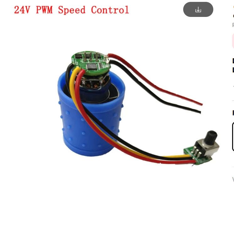
24 volt fan with PWM control
-
I have connected the fan and set the parameter Q1000. If I set the speed in the DWC to 95%, the motor burns out!
-
Can you give more detail about what exactly you are connecting?
-
Hello ,
I have
+24V at Out5 / V_OutLC1
-Out 5 / GND
PWM at Out 5 / out5-in config.g
M950 F2 C‘!out5’ Q1000
M106 P2 S0.0 H-1 C ‘Blower’ -
@Zseven I assume this is a CPAP/vacuum blower control PCB and not a standard fan, is that correct?
-
Yes !
-
@Zseven then you need to give us more details. Type of blower, how everything is wired between the PCB and the Blower and the control board, etc.
I highly doubt the Duet board can burn out the big blower because those fan ports are limited to 1A; I assume the blowers pull more than that.
-
Hello ,
I have requested the data sheet from the manufacturer. -
ello ,
I have now got a replacement as the last fan has burnt out.
DC7-24V brushless turbo fan motor 100000 rpm high speed aluminium alloy impeller with brushless motor and speed controller
I have now connected the fan direnkt to the 24V power supply and I can control it very well with the potentiometer
I have now measured the voltage at the potentiometer and between the red and black cable are 5V
The yellow cable should be the PWM signal.
How can I now control this fan with the Duet 6xd?
Witch pins ?
-
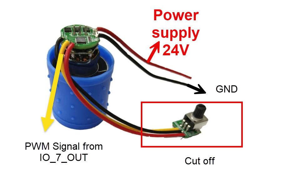
The wiring on the photo does not match the wiring on the PCB graphics.
If you could provide a link to the listing and/or a full spec sheet that would help. "PWM control" can mean different things, in this case it could be 0-5V for example which would require extra circuitry.
-
I have fix it !
-
@Zseven please share your fixed setup for the benefit of all (-;
-
