Z wont go to the corect dept when printing.
-
@droftarts
So this
Checking the trigger heightThe Z probe trigger height must not vary significantly with XY position. Measure the trigger height of your Z probe at various XY positions and make sure it is consistent. To measure the trigger height:
Make sure there is no filament stuck to the nozzle (you may want to do this test with the nozzle hot)
Cancel any existing bed compensation by sending M561
Send M564 S0 to allow movement lower than where the firmware thinks Z=0 is. This is to ensure that you can lower the nozzle all the way to the bed in step 5.
Command the print head to the XY coordinates you want to probe. This can be any place where both the nozzle and the probe are over the bed. Either use the jog buttons in DWC, or send a G1 command (eg G1 X100 Y100) to move to a specific location.
Command the print head down in small steps, using the jog buttons in DWC or by sending individual G1 Z[value] commands, until the nozzle just touches the bed or just grips a sheet of paper. You may also wish to create a macro to lower the head by e.g. 0.02mm to get greater accuracy (G91 followed by G1 Z-0.02).
Send G92 Z0 to define that height as Z=0
Command the nozzle up 5mm (G1 Z5)
Send G30 S-1 to probe the bed without resetting the Z=0 position
Read off the Z height from the web interface. That is the trigger height.
Repeat the previous two steps a couple of times to make sure you are getting a consistent result
Repeat steps 4-10 for the other XY positions you want to check.
Does nothing?
-
@droftarts
G1 Z-1.97 F50 ; Nozzle Z0 Y200 X160
G92 Z0
G1 Z5
G30 S-1
Stopped at height 4.054 mmGot G30 S-1
Stopped at height 4.054 mm to give a consistent result.is 4.054 mm the nozzle height?
; Probes
M558 K0 P9 C"io7.in" H5 F120 T6000 ; configure BLTouch probe via slot #0
G31 P500 X45 Y0 Z4.054 ; set Z probe trigger value, offset and trigger height
M950 S0 C"io7.out" ; create servo #0 for BLtouch
M557 X0:400 Y0:400 S20???
-
@Snippy said in Z wont go to the corect dept when printing.:
is 4.054 mm the nozzle height?
Yes.
G31 P500 X45 Y0 Z4.054 ; set Z probe trigger value, offset and trigger heightYes, put it in the G31 Z parameter.
Your instructions are missing a couple of steps at the end, where it explains how to put the Z offset in G31. Where did you get them from? Proper instructions here https://docs.duet3d.com/en/User_manual/Connecting_hardware/Z_probe_testing#calibrate-the-z-probe-trigger-height
Ian
Bed-slinger - Mini5+ WiFi/1LC | RRP Fisher v1 - D2 WiFi | Polargraph - D2 WiFi | TronXY X5S - 6HC/Roto | CNC router - 6HC | Tractus3D T1250 - D2 Eth
-
@droftarts
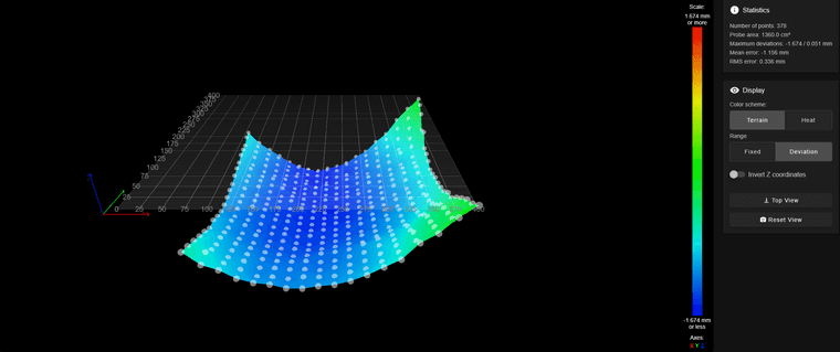
Warning: the height map has a substantial Z offset. Suggest use Z-probe to establish Z=0 datum, then re-probe the mesh.
378 points probed, min error -1.674, max error 0.051, mean -1.157, deviation 0.336
Height map saved to file 0:/sys/heightmap.csvRepRapFirmware height map file v2 generated at 2025-02-22 20:45, min error -1.674, max error 0.051, mean -1.157, deviation 0.336
axis0,axis1,min0,max0,min1,max1,radius,spacing0,spacing1,num0,num1
X,Y,0.00,400.00,0.00,400.00,-1.00,20.00,20.00,21,21
0, 0, 0, -0.605, -0.800, -0.884, -1.019, -1.089, -1.116, -1.179, -1.183, -1.143, -1.120, -1.058, -0.961, -0.838, -0.719, -0.471, -0.333, -0.113, 0.051
0, 0, 0, -0.675, -0.775, -0.954, -1.056, -1.180, -1.183, -1.220, -1.180, -1.185, -1.170, -1.103, -1.048, -0.930, -0.776, -0.600, -0.391, -0.270, -0.060
0, 0, 0, -0.748, -0.904, -1.031, -1.089, -1.210, -1.211, -1.238, -1.233, -1.254, -1.203, -1.158, -1.091, -0.970, -0.830, -0.620, -0.461, -0.331, -0.129
0, 0, 0, -0.828, -0.978, -1.079, -1.143, -1.230, -1.265, -1.275, -1.261, -1.285, -1.261, -1.185, -1.111, -0.988, -0.903, -0.738, -0.518, -0.384, -0.235
0, 0, 0, -0.900, -1.009, -1.120, -1.199, -1.276, -1.316, -1.351, -1.334, -1.295, -1.266, -1.224, -1.124, -1.035, -0.971, -0.818, -0.628, -0.464, -0.349
0, 0, 0, -0.990, -1.073, -1.190, -1.268, -1.328, -1.373, -1.375, -1.401, -1.382, -1.338, -1.280, -1.254, -1.145, -1.046, -0.945, -0.783, -0.598, -0.480
0, 0, 0, -0.989, -1.136, -1.244, -1.271, -1.396, -1.386, -1.431, -1.460, -1.424, -1.394, -1.348, -1.275, -1.200, -1.129, -1.021, -0.856, -0.704, -0.516
0, 0, 0, -1.059, -1.146, -1.230, -1.348, -1.399, -1.401, -1.458, -1.435, -1.471, -1.429, -1.400, -1.360, -1.253, -1.128, -1.063, -0.945, -0.784, -0.619
0, 0, 0, -1.106, -1.209, -1.278, -1.355, -1.419, -1.449, -1.485, -1.490, -1.471, -1.474, -1.399, -1.348, -1.263, -1.191, -1.078, -0.971, -0.815, -0.666
0, 0, 0, -1.110, -1.191, -1.298, -1.339, -1.408, -1.441, -1.489, -1.513, -1.501, -1.479, -1.464, -1.390, -1.305, -1.215, -1.149, -0.993, -0.919, -0.704
0, 0, 0, -1.096, -1.189, -1.280, -1.344, -1.451, -1.469, -1.513, -1.519, -1.531, -1.508, -1.497, -1.408, -1.291, -1.253, -1.141, -1.015, -0.884, -0.719
0, 0, 0, -1.074, -1.191, -1.294, -1.368, -1.438, -1.463, -1.441, -1.519, -1.550, -1.549, -1.479, -1.426, -1.341, -1.250, -1.174, -1.054, -0.930, -0.760
0, 0, 0, -1.073, -1.165, -1.308, -1.382, -1.439, -1.421, -1.505, -1.546, -1.551, -1.556, -1.499, -1.438, -1.350, -1.258, -1.104, -0.994, -0.853, -0.789
0, 0, 0, -1.015, -1.134, -1.243, -1.356, -1.461, -1.454, -1.519, -1.570, -1.531, -1.509, -1.460, -1.398, -1.344, -1.268, -1.106, -0.966, -0.840, -0.730
0, 0, 0, -0.978, -1.141, -1.239, -1.335, -1.398, -1.504, -1.528, -1.513, -1.558, -1.529, -1.485, -1.440, -1.274, -1.264, -1.111, -0.974, -0.870, -0.684
0, 0, 0, -0.963, -1.093, -1.264, -1.308, -1.446, -1.535, -1.539, -1.504, -1.551, -1.511, -1.485, -1.411, -1.270, -1.238, -1.115, -1.011, -0.853, -0.670
0, 0, 0, -0.903, -1.123, -1.273, -1.364, -1.435, -1.510, -1.540, -1.638, -1.565, -1.523, -1.438, -1.393, -1.313, -1.148, -1.059, -0.859, -0.734, -0.438
0, 0, 0, -0.886, -1.054, -1.238, -1.360, -1.470, -1.483, -1.593, -1.606, -1.634, -1.499, -1.463, -1.420, -1.233, -1.136, -1.018, -0.889, -0.655, -0.490
0, 0, 0, -0.893, -1.041, -1.201, -1.326, -1.456, -1.538, -1.558, -1.581, -1.623, -1.458, -1.550, -1.406, -1.240, -1.071, -0.921, -0.755, -0.531, -0.239
0, 0, 0, -0.803, -1.013, -1.186, -1.266, -1.478, -1.486, -1.531, -1.596, -1.548, -1.604, -1.414, -1.368, -1.214, -1.053, -0.858, -0.620, -0.405, -0.129
0, 0, 0, -0.789, -1.018, -1.173, -1.314, -1.465, -1.564, -1.658, -1.674, -1.616, -1.563, -1.483, -1.334, -1.213, -0.993, -0.819, -0.514, -0.275, -0.075Got this far again, No matter where i try to establish the Z=0 datum allways the same error.
What i can tell from this height map that it is the most accurate so far.
Still the height map does ''jack shit'' when it comes to printing, nozzle wont go Z- It can only go Z+.
Why??? -
G1 Z-1.97 F50 ; Nozzle Z0 Y200 X160
G92 Z0
G1 Z5
G30 S-1Why are you doing the G92 Z0 - that is quite likely going to mess things up entirely.
Before you can use mesh compensation you first have to insure your Z probe is correct configured so that setting the Z**=0 Datum**, using G30, gives the correct result.
After doing a G30 (usually at the center of the bed) you can then, using the DWC, "nudge" the bed toward the nozzle of the hotend. When the bed just touches the top of the nozzle the DWC should report the Z position as 0 (zero).
If it does not you need to adjust the Z trigger height of your Z probe configuration until you do get Z=0 when the bed just touches the nozzle.
It will like take several attempts to find the exact value you need for your Z probe.
Once the Z probe is working then and only then can you create an accurate height map. You must always use G30 to set the Z=0 Datum BEFORE using G29 to create the height map or when loading the height map.
Frederick
-
@fcwilt
https://docs.duet3d.com/en/User_manual/Connecting_hardware/Z_probe_testing#calibrate-the-z-probe-trigger-height
This is why -
My problem is that after get a height map from G29 the map does nothing to compensate when printing, Z does not moove in -Z only in Z+.
-
@Snippy said in Z wont go to the corect dept when printing.:
@fcwilt
https://docs.duet3d.com/en/User_manual/Connecting_hardware/Z_probe_testing#calibrate-the-z-probe-trigger-height
This is whyOK - so the bed was just touching the nozzle at that point when you set Z=0?
Frederick
Printers: a E3D MS/TC setup and a RatRig Hybrid. Using Duet 3 hardware running 3.4.6
-
@Snippy said in Z wont go to the corect dept when printing.:
My problem is that after get a height map from G29 the map does nothing to compensate when printing, Z does not moove in -Z only in Z+.
Well how it should move would depend on the height map values and the height map value nearest to where the Z=0 Datum was set.
If the Z=0 Datum happened to be set equal to the lowest point of the mesh then movement would only be in Z+, as all of the other points, being higher, would need to be lowered.
Frederick
-
@fcwilt Z datum was set to the highest part, So in order to print Z should go in the -
,
-
@fcwilt
Yes -
@Snippy Can you post your config.g file? Specifically looking for your M208 line based on the following quote:
@Snippy said in Z wont go to the corect dept when printing.:
My problem is that after get a height map from G29 the map does nothing to compensate when printing, Z does not moove in -Z only in Z+.
Edit: Your bed does not look healthy lol.
-
@Snippy said in Z wont go to the corect dept when printing.:
Z datum was set to the highest part, So in order to print Z should go in the -
I assume you have verified that the Z axis moves in the correct direction when controlled from the DWC?
Frederick
P.S. Just out of curiosity what is the bed made from? It seems to have quite a bit of curve.
Here is the height map from one of my better printers. I had the bed created by a local machinist and it is very flat. Even came with a certificate.
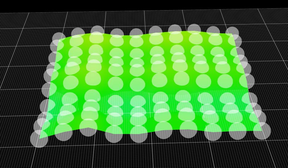
Printers: a E3D MS/TC setup and a RatRig Hybrid. Using Duet 3 hardware running 3.4.6
-
@fcwilt
Bed is https://www.aliexpress.com/item/1005003056403054.html?spm=a2g0o.order_list.order_list_main.84.71821802lt2l0t
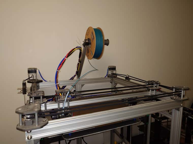
The printer is homebrew 100%, Core XY
Printed parts are mostly nylon with 10% carbonfiber.
So far ~900€ in parts. -
@fcwilt
And yes, Z mooves corectly.
Only problem i have is the mesh bed compensation does absolutely nothing.
And i might have a solution for the bed being a dish, ill just drill and tap some holes in the bed subplate 6mm 7068 aluminium plate and use some extra bolts with rubber tips to push out the bow. -
@Snippy so you are homing the bed at the one of the high corners eg X0 Y0? Generally you should home Z at either the ‘most used’ point (usually the bed centre) or the lowest point (in your case also the bed centre), and the mesh is better positive, because negative moves are limited, because the nozzle won’t move below Z0 (unless your M208 allows it, or you have sent the Gcode to allow moves outside the machine limits). ie if your printing at 0.1mm layer height, and your mesh needs -1mm of movement, it’s only going to move -0.1mm.
Ian
-
@sebkritikel
; Smart Drivers
M569 P0.0 S1 D3 V2000 ; driver 0.0 goes forwards (extruder 0)
M569 P0.1 S0 D3 V2000 ; driver 0.1 goes forwards (Z axis)
M569 P0.2 S0 D3 V2000 ; driver 0.2 goes forwards (Z axis)
M569 P0.3 S0 D3 V2000 ; driver 0.3 goes backwards (X axis)
M569 P0.4 S0 D3 V2000 ; driver 0.4 goes backwards (Y axis); Motor Idle Current Reduction
M906 I30 ; set motor current idle factor
M84 S30 ; set motor current idle timeout; Axes
M584 X0.3 Y0.4 Z0.1:0.2 ; set axis mapping
M350 X16 Y16 Z16 I1 ; configure microstepping with interpolation
M906 X1040 Y1040 Z1040 ; set axis driver currents
M92 X80 Y80 Z800 ; configure steps per mm
M208 X0:400 Y0:400 Z0:220 ; set minimum and maximum axis limits
M566 X4000 Y4000 Z4000 ; set maximum instantaneous speed changes (mm/min)
M203 X35000 Y35000 Z1500 ; set maximum speeds (mm/min)
M201 X10000 Y10000 Z10000 ; set accelerations (mm/s^2); Extruders
M584 E0.0 ; set extruder mapping
M350 E16 I1 ; configure microstepping with interpolation
M906 E940 ; set extruder driver currents
M92 E409 ; configure steps per mm
M566 E120 ; set maximum instantaneous speed changes (mm/min)
M203 E3600 ; set maximum speeds (mm/min)
M201 E250 ; set accelerations (mm/s^2); Kinematics
M669 K1 ; configure CoreXY kinematics; Endstops
M574 X1 P"!io1.in" S1 ; configure X axis endstop
M574 Y1 P"!io2.in" S1 ; configure Y axis endstop
M574 Z1 P"!io3.in" S1 ; configure Z axis endstop; Probes
M558 K0 P9 C"io7.in" H5 F120 T6000 ; configure BLTouch probe via slot #0
G31 P500 X45 Y0 Z4.054 ; set Z probe trigger value, offset and trigger height
M950 S0 C"io7.out" ; create servo #0 for BLtouch
M557 X0:400 Y0:400 S20; Sensors
M308 S0 P"temp1" Y"thermistor" A"Heated Bed" T100000 B3950 C7.06e-8 ; configure sensor #0
M308 S1 P"temp0" Y"thermistor" A"Nozzle" T100000 B4725 C7.06e-8 ; configure sensor #1; Heaters
M950 H0 C"out0" T0 ; create heater #0
M143 H0 P0 T0 C0 S110 A0 ; configure heater monitor #0 for heater #0
M307 H0 R0.128 K0.179:0.000 D11.50 E1.35 S1.00 B0 ; configure model of heater #0
M950 H1 C"out1" T1 ; create heater #1
M143 H1 P0 T1 C0 S300 A0 ; configure heater monitor #0 for heater #1
M307 H1 R1.040 K0.469:0.000 D10.85 E1.35 S1.00 B0 V23.9 ; configure model of heater #1; Heated beds
M140 P0 H0 ; configure heated bed #0; Fans
M950 F0 C"out4+out4.tach" Q8 ; create fan #0
M106 P0 C"PCF" S0 L0 X1 B0.1 ; configure fan #0; Tools
M563 P0 D0 H1 F0 ; create tool #0
M568 P0 R0 S0 ; set initial tool #0 active and standby temperatures to 0C; Miscellaneous
T0 ; select first tool -
@Snippy said in Z wont go to the corect dept when printing.:
M208 X0:400 Y0:400 Z0:220 ; set minimum and maximum axis limits
This, combined with what @droftarts is saying about where you're setting your Z datum , is why you're not seeing compensation occur in the negative Z direction. You could allow for negative moves in the Z direction, such as
M208 Z-5:220and/or adjust where you're setting the Z datum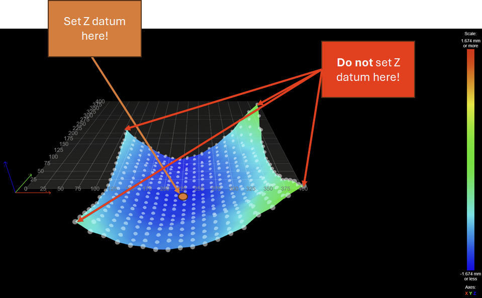
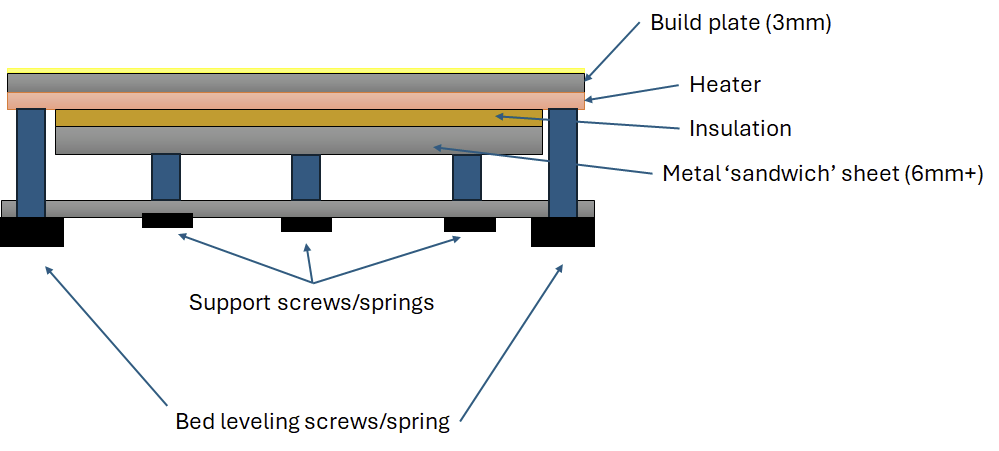
For a 410mmx410mm bed, a thickness of 3mm without supporting the underside will result in poor dimension accuracy for your parts, as the bed will naturally sag in the middle. 1.6mm is substantial. I would recommend a thicker bed in the range of 10mm to 12mm, or some adjustable screws to help support the center of the bed.
-
@sebkritikel
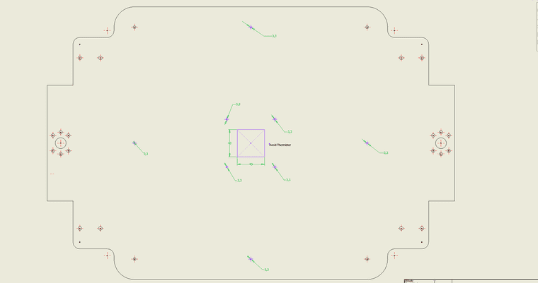
Purple stuff is the added leveling for the sub bed, tap to M4 and using bolts with rubber tips to push the bed.
This enought for leveling, or should i tap a 20x20 grid on the whole surface?
-
@Snippy 20x20 grid is likely overkill. Based on the 3mm thickness, you could probably do some calculations (or find a calculator) to derive a linear spacing of supports driven by what you would consider a reasonable bed deflection value - could start with .1mm. Unfortunately 3mm is really, really thin, especially at that size.
Is your bed heater a silicone type?
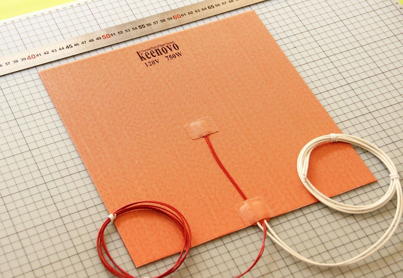
Depending on what type of rubber tips you have in mind, I'd be concerned about their temperature rating, plus potential long term wear on the underside of the bed. What would be better is having a thicker sheet sandwiched below the bed heater. Not the best idea (or best sketch) buy maybe can mitigate the sagging bed.