Problems with new Laser Filament Monitor
-
@insertnamehere said in Problems with new Laser Filament Monitor:
So if I mounted the sensor downstream from the extruder all the issues I see would go away. However, I plan to move to a direct drive soon so this solution is out of the question.
At least until then you could modify your sensor holder to have a way to additionally attach the bowden tube downstream of it and use the extruder the "right way around" as @deckingman already suggested. I know this will only solve your issues as long as you are using the bowden setup but this will be better than not being able to use the sensor at all with some filaments.
-
@deckingman said in Problems with new Laser Filament Monitor:
Errr what?? I have 5 BMGs on my printer and trust me, with Bowden you still feed filament in at the top and out at the bottom. You just use a Bowden adaptor which fits in the groove mount, instead of the E3D heat sink.
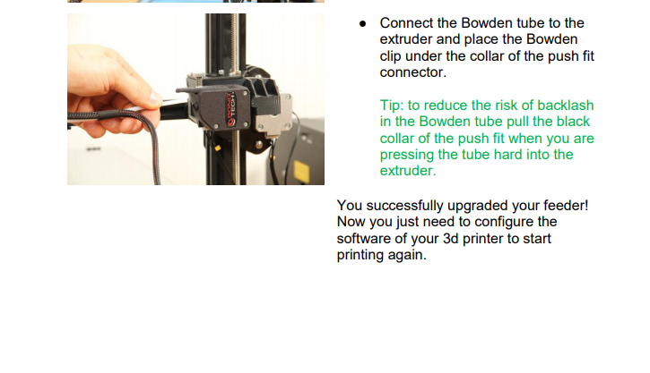
From the Bondtech BMG installation manual. It also states that the drive to the extruder stepper needs to be reversed
https://www.bondtech.se/wp-content/uploads/2018/08/Bondtech-Creality-CR-10-Installation-Guide-V1.0.pdf
-
@insertnamehere The rotation direction of the motor needs to be reversed compared to an original CR10. It doesn't mean that you fit the entire unit back to front or upside down. I have both left and right hand versions on my printer and the left hand versions have opposite motor rotation to the right hand version because the driven gear is on the opposite side of the filament. That's all it means.
-
@deckingman said in Problems with new Laser Filament Monitor:
@insertnamehere The rotation direction of the motor needs to be reversed compared to an original CR10. It doesn't mean that you fit the entire unit back to front or upside down. I have both left and right hand versions on my printer and the left hand versions have opposite motor rotation to the right hand version because the driven gear is on the opposite side of the filament. That's all it means.
You did see the picture above yes? You see that the bowden tube going into the bowden push fit adapter?
-
@deckingman It does seem odd, and I'm not sure why Bondtech recommends it (unless there's not space to mount it conventionally, hard to tell), but I would say from the photo that @insertnamehere is correct, the filament travels from right to left in that photo. Otherwise, putting the microswitch on the (typically) discharge end of the Bondtech wouldn't do any good, as it would never see that filament had run out.
-
You can use a hobbs wheel and use the laser sensor to measure the hobbs movement instead. The it will work independently of filament type.
-
I have two BMG's and Bondtech DEFINITELY suggest using it with filament going in either direction. Especially based on the 3D printable parts they suggest using. I thought it was odd when I realized what they were suggesting too. In my case they are both direct drive to E3Dv6 so I have to figure out how to use my laser sensors. I ordered one for both of my printers.
Making filament move a wheel for the sensor to watch adds complexity but it might be the best way to use optical sensing? I may have to remix something on Thingi. You probably want to gear UP the movement, or make the wheel diameter where the filament runs past a lot smaller than the sensor part of the wheel. Aren't you skirting very close to just using a purpose built optical encoder though at this point?

-
@T3P3Tony I want to hold off on the RMA until you can try the eSun filament. There is a chance it may work for you and the problem is mine.
I really like the concept of the filament sensor and really would like it to work. Can you let me know if you have been able to test with the filament I use?
-
@T3P3Tony Just a question on the design of the laser monitor.
Looks like the optical sensor is mounted perpendicular to the filament.Am I correct?
If so, I'm wondering why this design choice was made, given that laser sensors and the LED in optical mice are positioned opposite each at angles to the surface so the light source can illuminate the surface irregularities better.
Out of interest I ran the problem PETG filament length-ways over the sensor on a laser mouse. Had no problems sensing movement.
I know, not exactly rigorous testing, but interesting.
-
@elmoret said in Problems with new Laser Filament Monitor:
@deckingman It does seem odd, and I'm not sure why Bondtech recommends it (unless there's not space to mount it conventionally, hard to tell), but I would say from the photo that @insertnamehere is correct, the filament travels from right to left in that photo. Otherwise, putting the microswitch on the (typically) discharge end of the Bondtech wouldn't do any good, as it would never see that filament had run out.
OK I concede and apologise. I was using my 'phone so didn't look at the picture. In my defence, I did say in my OP that it might work. However, it still seems an odd thing to do especially as the BMG is available in both left and right hand versions to enable access to the release lever for any installation.
-
@insertnamehere said in Problems with new Laser Filament Monitor:
@T3P3Tony Just a question on the design of the laser monitor.
Looks like the optical sensor is mounted perpendicular to the filament.Am I correct?
If so, I'm wondering why this design choice was made, given that laser sensors and the LED in optical mice are positioned opposite each at angles to the surface so the light source can illuminate the surface irregularities better.
Out of interest I ran the problem PETG filament length-ways over the sensor on a laser mouse. Had no problems sensing movement.
I know, not exactly rigorous testing, but interesting.
In the sensing chip, the image sensor is mounted next to the laser. So we can't control the distance between them, only the distance to the filament and the direction that the filament runs. At present we have the filament running over the centre of the laser and the centre of the image sensor, which I thought would give the best response. I guess we could try running the filament at right angles to that direction, in which case it would have to run over the centre of the laser but would not run over the image sensor at all.
-
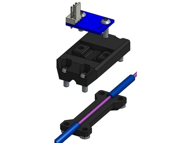
Have you tried my casing design? I have a large exposed length of filament based on a hypothetical aperture I calculated from some datasheet parameters.
I had no issues with shiny metallic petg or translucent materials with it. Just make sure you cut the filament tip diagonally so it enters the exit hole nicely


-
@brunofporto Thanks, I have not tried it but will do!
-
@brunofporto said in Problems with new Laser Filament Monitor:
Have you tried my casing design? I have a large exposed length of filament based on a hypothetical aperture I calculated from some datasheet parameters.
I had no issues with shiny metallic petg or translucent materials with it. Just make sure you cut the filament tip diagonally so it enters the exit hole nicely


In fact I used your design first. I liked the look of it.
After I found that I had problems sensing shiny petg I switched to the Duet reference design.
I found both yours and the reference casing gave the same results.Since you and @T3P3Tony have had reasonable results sensing petg maybe it's just that I have a faulty sensor?
When @T3P3Tony can test the same filament type this may prove to be the case.
-
David has also suggested we test filament at an angle.
@insertnamehere I have ordered the esun filament but it is not on a fast delivery here in the UK for some reason (Amazon - next week) so will test ASAP.
-
@insertnamehere said in Problems with new Laser Filament Monitor:
I found both yours and the reference casing gave the same results.
Thanks!!!
 I will make a shorter version then, this one sometimes is very difficult to feed the filament. And I will adopt your hold solution (use the groove mounting as I have a similar extruder setup).
 -
@brunofporto said in Problems with new Laser Filament Monitor:
Have you tried my casing design? I have a large exposed length of filament based on a hypothetical aperture I calculated from some datasheet parameters.
I had no issues with shiny metallic petg or translucent materials with it. Just make sure you cut the filament tip diagonally so it enters the exit hole nicely


I modified your housing to run the filament through at a 10 angle to see if it makes any difference in the accuracy. I don't post on Thingiverse but here is a link to the STL files. Note I have not printed these yet so there could be fit issues.
https://drive.google.com/drive/folders/1b8wBl5uZ1qwoimONZLIcWlFULOlNsJaq?usp=sharing


Once I confirm if the angle approach works I will go back and "pretty up" the housing.
-
@t3p3tony said in Problems with new Laser Filament Monitor:
David has also suggested we test filament at an angle.
@insertnamehere I have ordered the esun filament but it is not on a fast delivery here in the UK for some reason (Amazon - next week) so will test ASAP.
I will be testing this theory by Friday. I'll report back.
-
@timcurtis67 It is already pretty

-
Since the prusa laser filament monitor uses the same sensor as the Duet, I did a few searches and turns out that the prusa sensor has problems with black petg also. Prominently eSun.
https://www.reddit.com/r/prusa3d/comments/83sq1f/problems_with_mk3_filament_sensor_with_black_petg/