Duet3D Logo Duet3D
    • Tags
    • Documentation
    • Order
    • Register
    • Login

    Best lead screw - ball bearing mount system

    Scheduled Pinned Locked Moved
    3D Printing General Chat
    13
    42
    5.2k
    Loading More Posts
    • Oldest to Newest
    • Newest to Oldest
    • Most Votes
    Reply
    • Reply as topic
    Log in to reply
    This topic has been deleted. Only users with topic management privileges can see it.
    • Vetiundefined
      Veti
      last edited by

      what about sfu1204. you would not need the coupler.

      1 Reply Last reply Reply Quote 0
      • DocTruckerundefined
        DocTrucker
        last edited by

        Is the pulley for belt reduction or tying the three lead screws to one stepper?

        If the former I would recommend worm reduction drive instead to reduce the chance of the elevator driving itself down under it's own weight. I was going to look into breaks for my belt reduction system but someone rightly pointed out worm reduction was potentially a better option.

        Running 3 P3Steel with Duet 2. Duet 3 on the shelf looking for a suitable machine. One first generation Duet in a Logo/Turtle style robot!

        deckingmanundefined Phaedruxundefined 2 Replies Last reply Reply Quote 0
        • deckingmanundefined
          deckingman @DocTrucker
          last edited by

          @doctrucker From other posts, I think he was gunning for a continuous belt/single motor (but I could be wrong).

          The simplest way to prevent the weight of the bed from driving the screws is to use a finer lead screws with correspondingly shallower helix angles.

          Worm drives are OK (ish) - the problem is eliminating backlash. If you have a sufficiently heavy bed and a very steep helix angle on the thread (very course lead), then gravity will take care of any backlash, but finer lead screws are all together a simpler and (IMO) more elegant solution.

          Ian
          https://somei3deas.wordpress.com/
          https://www.youtube.com/@deckingman

          1 Reply Last reply Reply Quote 0
          • Phaedruxundefined
            Phaedrux Moderator @DocTrucker
            last edited by

            @doctrucker said in Best lead screw - ball bearing mount system:

            Is the pulley for belt reduction or tying the three lead screws to one stepper?

            If the former I would recommend worm reduction drive instead to reduce the chance of the elevator driving itself down under it's own weight. I was going to look into breaks for my belt reduction system but someone rightly pointed out worm reduction was potentially a better option.

            I think his lead screws are 2mm pitch/lead single start, so shouldn't have much auto rotation potential.

            Z-Bot CoreXY Build | Thingiverse Profile

            1 Reply Last reply Reply Quote 0
            • Stephen6309undefined
              Stephen6309
              last edited by

              On my corexy using makerslide. I have only a 608 bearing and the pulley keeping the tr8-8 in place with gravity. One belt runs the two leadscrews from the stepper motor at 2:1. The bed will move down if I press hard down on it, otherwise it doesn't move.

              1 Reply Last reply Reply Quote 0
              • gnydickundefined
                gnydick
                last edited by

                If your bed is mounted rigidly and can't move in X or Y, then the lead screw really doesn't have to be all that good. I use a floating lead screw nut because lead screws aren't perfect, but the linear rails that my bed is mounted to is precise. I've seen ZERO artifacts from the float.

                deckingmanundefined 1 Reply Last reply Reply Quote 0
                • deckingmanundefined
                  deckingman @gnydick
                  last edited by

                  @gnydick I'll second that. Lead screws should only provide lift, guides should only guide. I had a bit of an accident a few months ago and bent one of the lead screws. I've never got around to straightening or replacing it because it prints perfectly. The screw might wobble a bit, but one rotation still gives me exactly 1mm of linear movement.

                  Ian
                  https://somei3deas.wordpress.com/
                  https://www.youtube.com/@deckingman

                  gnydickundefined 1 Reply Last reply Reply Quote 0
                  • gnydickundefined
                    gnydick @deckingman
                    last edited by

                    @deckingman I had the exact same thing happen!!

                    1 Reply Last reply Reply Quote 0
                    • claustroundefined
                      claustro
                      last edited by

                      Thank you for all your suggestions.
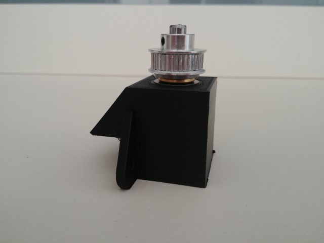
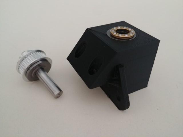
                      This is what come out .
                      I moved the thrust bearing on the top so it can discharge the weight of the bed on the plastic structure.
                      Below I installed the ball bearing that doesn't have to manage weight.
                      I am still waiting for the rigid coupler.

                      what do you think
                      ?
                      2_1559396358318_20190601_151644 (Piccola).jpg 1_1559396358318_20190601_151656 (Piccola).jpg 0_1559396358317_20190601_151713 (Piccola).jpg

                      1 Reply Last reply Reply Quote 0
                      • Phaedruxundefined
                        Phaedrux Moderator
                        last edited by

                        Looks good to me.

                        Z-Bot CoreXY Build | Thingiverse Profile

                        1 Reply Last reply Reply Quote 0
                        • deckingmanundefined
                          deckingman
                          last edited by

                          That'll do.

                          Ian
                          https://somei3deas.wordpress.com/
                          https://www.youtube.com/@deckingman

                          1 Reply Last reply Reply Quote 0
                          • mrehorstdmdundefined
                            mrehorstdmd
                            last edited by mrehorstdmd

                            With this sort of thing I tend to think about what might go wrong and what I can do to prevent it. I try to only have to do things once. Making things as close to ideal (in the relevant properties) as possible reduces the things you have to consider if something goes wrong. If I use a plastic part in an assembly I tend to make it bulky to ensure rigidity, so I wouldn't use thin plastic flanges, even with side-webbing, to support a relatively large weight or something that will be loaded by a drive belt.

                            At the very least I would thicken the flange that bolts to the top side of the t-slot, maybe to the point of making it continuous with the body of the part. I'm not saying that your flange design won't be adequate, but if it isn't, you'll be redesigning and reprinting.

                            In the end, you should worry less about the plastic flexing and more about the t-slot it's bolted to twisting.

                            https://drmrehorst.blogspot.com/

                            claustroundefined 1 Reply Last reply Reply Quote 0
                            • claustroundefined
                              claustro @mrehorstdmd
                              last edited by

                              @mrehorstdmd
                              is something like this enough "bulky"?

                              0_1559405728244_lead screw mount 2 v2.jpg

                              1 Reply Last reply Reply Quote 0
                              • mrehorstdmdundefined
                                mrehorstdmd
                                last edited by

                                Yes, I'd do something like that. I'd also use modifier meshes to increase the fill density around the mounting bolt holes.

                                https://drmrehorst.blogspot.com/

                                1 Reply Last reply Reply Quote 0
                                • Vetiundefined
                                  Veti
                                  last edited by

                                  that reminds me there was a video by alex kenis about this
                                  https://www.youtube.com/watch?v=2Z7mZVvPlc8

                                  1 Reply Last reply Reply Quote 0
                                  • claustroundefined
                                    claustro
                                    last edited by

                                    While I am trying to fix the squareness of the frame I finalized!the Z axis belt system
                                    This is what it came out.
                                    I tried to make the belt running as much as possible around the pulley with this setup all the pulley has 180 degree belt contact.
                                    The 2 tensioners are temporary , I am going to print a support for it
                                    Any suggestion will be appreciated.
                                    Thank you
                                    Andrea
                                    0_1559588633233_20190603_173238 (Medium).jpg

                                    deckingmanundefined gnydickundefined 2 Replies Last reply Reply Quote 1
                                    • deckingmanundefined
                                      deckingman @claustro
                                      last edited by

                                      @claustro How come those front two lead screws are set so far back from the front of the frame?

                                      Ian
                                      https://somei3deas.wordpress.com/
                                      https://www.youtube.com/@deckingman

                                      claustroundefined 1 Reply Last reply Reply Quote 0
                                      • claustroundefined
                                        claustro @deckingman
                                        last edited by

                                        @deckingman this is only a temporary disposition , at the end the 2 front lead screw will be as far as possible from the back one

                                        deckingmanundefined 1 Reply Last reply Reply Quote 0
                                        • deckingmanundefined
                                          deckingman @claustro
                                          last edited by

                                          @claustro said in Best lead screw - ball bearing mount system:

                                          @deckingman this is only a temporary disposition , at the end the 2 front lead screw will be as far as possible from the back one

                                          Ah OK. I was a bit concerned that the two side rails might flex due to the weight of the bed acting so far away from the end fixings. Those "Tee plates" might flex though. If you can, check for any deflection by using a dial gauge if you can lay your hands on one, and adding a weight to simulate the weight of the bed to the top of the lead screw couplings.

                                          Ian
                                          https://somei3deas.wordpress.com/
                                          https://www.youtube.com/@deckingman

                                          claustroundefined 1 Reply Last reply Reply Quote 0
                                          • claustroundefined
                                            claustro @deckingman
                                            last edited by

                                            @deckingman

                                            I am trying to use your Z rail configuration with only 2 carriage in a diagonal disposition .
                                            If you talking about the plastic tee plate , the one that fix the 2020 that support the 2 front lead screws, I am going to switch to aluminum one as soon I 'll have my CNC running . ( it will be my first easy test with aluminum 🙂 )

                                            I have a dial gauge and I surely check what you suggest.

                                            0_1559593583822_Immagine.jpg

                                            deckingmanundefined 1 Reply Last reply Reply Quote 0
                                            • First post
                                              Last post
                                            Unless otherwise noted, all forum content is licensed under CC-BY-SA