seeing if i can get assistance with bed connectins
-
@frnknstn, do you know the power specifications (in watts or amps) of your bed heater and 24V power supply? You need to make sure the power supply can provide power to the bed, motors, nozzle, fans, electronics, etc.
-
Your config shows bed on OUT0 and extruder on OUT1
; Heaters
M950 H0 C"out0" T0 ; create bed heater output on out0 and map it to sensor 0
M950 H1 C"out1" T1 ; create nozzle heater output on out1 and map it to sensor 1
But you say:
i ran the bed to out1 and ran 24 volts to the out1 inCan you describe your connections using the names in the Duet3 wiring diagram image here so we know what you mean by out1 in?
Maybe also post an image of the board and wiring so we can see the jumper settings.
-
@alankilian ```
; Heaters
M308 S0 P"temp_0" Y"thermistor" A"Bed" T100000 B4138 ; configure sensor 0 as thermistor on pin temp0
M950 H0 C"out_0" T0 ; create bed heater output on out0 and map it to sensor 0
M307 H1 A350 C139 D5.5 B0 ; set model parameters for heater 1 and use PID mode
M140 H0 ; map heated bed to heater 0
M143 H0 S120 ; set temperature limit for heater 0 to 120CM308 S1 P"temp_1" Y"thermistor" A"Hotend" T100000 B4725 C7.06e-8 ; configure sensor 1 as thermistor on pin temp1
M950 H1 C"out_1" T1 ; create nozzle heater output on out1 and map it to sensor 1
M307 H1 B0 R1.680 C233.0:193.0 D6.75 S1.00 V23.7 ; disable bang-bang mode for heater and set PWM limit
M143 H1 S280 ; set temperature limit for heater 1 to 280C -
@frnknstn so i have my heat straightened out almost.. i started tuning but i cant get the fans to go. ill send a pic of my board
-
M308 S0 P"temp_0" Y"thermistor" A"Bed" T100000 B4138 ; configure sensor 0 as thermistor on pin temp0 M950 H0 C"out_0" T0 ; create bed heater output on out0 and map it to sensor 0 M307 H1 A350 C139 D5.5 B0 ; set model parameters for heater 1 and use PID mode M140 H0 ; map heated bed to heater 0 M143 H0 S120 ; set temperature limit for heater 0 to 120CShouldn't that M307 be H0?
-
@alankilian i will see. the bed heats up and the extruder heats up. i will see what happens
-
.png](/assets/uploads/files/1639421738029-5c5a624c-dc72-419c-9680-1fa78142d786-screenshot-2.png) image url)
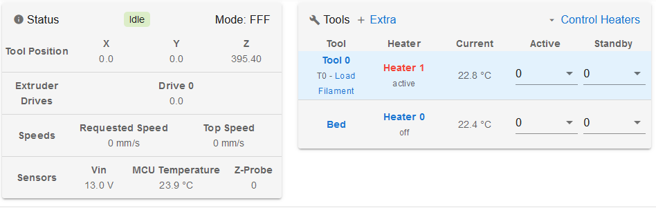
image url)I changed it and it actually seperated the bed and extruder into 2 seperate tools
-
@frnknstn now im just trying to get these fans going
-
Looks pretty much like mine:
-
@alankilian i still have to do z probe and fans. then bed leveling. paused on probe was getting frustrated. So i have been messing with heaters. Now im trying to figure out fans on extruder and parts cooler
-
@frnknstn so on my extruder fan, should i just run that always on by the power strip, i am running 24v fans throughout
-
@frnknstn Not all 24V fans can be PWM:ed Do you have more than two wire fans? Can you show how you connected them ?
Have you set the jumper to V_fused for 24V ?
-
@gixxerfast these are all 2 wire, i switched the jumper from 12v to VIN, both fans are coming out of out7 and out8. if i need to get different fans i can
-
@frnknstn said in seeing if i can get assistance with bed connectins:
@gixxerfast these are all 2 wire, i switched the jumper from 12v to VIN, both fans are coming out of out7 and out8. if i need to get different fans i can
ill see if i can get a pic
-
@frnknstn
No, they should work fine. At out7 (hotend fan) should start when T1 reaches 45C. YOu should be able to manually control out8 (part cooling) in the DWC dashboard. Have you tried?They are both two pin connectors so as long as you haven't rotated the wires you can't go wrong there
-
@gixxerfast i have no fans under fan selection. thats where i assumed they would show up
-
@frnknstn ill double check and make sure i have the wires correct
-
@frnknstn That is strange, not even the tool fan? ... Is your config still as listed above ?
Try a M98 P"0:/sys/config.g" and check the console
-
@frnknstn You might want to uncomment your tool config at the end of config.g and end with a T0
-
@gixxerfast ; General preferences
G90 ; Send absolute coordinates...
M83 ; ...but relative extruder moves; Network
M550 P"duet3" ; Set machine name
M552 S1 ; Enable network
;*** Access point is configured manually via M587
M586 P0 S1 ; Enable HTTP
M586 P1 S0 ; Disable FTP
M586 P2 S0 ; Disable Telnet
M575 P1 S1 B57600 ; Panel Due; Printer geometry
M669 K1 ; Select CoreXY mode
M208 X0:330 Y0:285.75 Z0:350 ; Axis Limits
M564 H0 ; allow unhomed movement;------- drives from top---------------------------------------------------
; B -------+------ A
; | P.02 | P.03 |
; -------+------- Z-Drives
; | P0.1 | P0.4 |
; -------+-------
; Front; Drive Mappings
M569 P0.0 S1 V0 ; Drive 0: E Axis
M569 P0.1 S1 V0 ; Drive 1: Z-LeftFront Axis
M569 P0.2 S0 V0 ; Drive 2: Z-LeftRear Axis
M569 P0.3 S1 V0 ; Drive 3: Z-RightRear Axis
M569 P0.4 S0 V0 ; Drive 4: Z-RightFront Axis
M569 P1.0 S1 V0 ; Drive 5: Expansion: B motor (X-axis)
M569 P1.1 S1 V0 ; Drive 6: Expansion: A motor (Y-axis); Motor remapping for dual Z and axis Limits
M584 X1.0 Y1.1 Z0.1:0.2:0.3:0.4 E0.0 ; Motor mapping
M671 X-76.2:-76.2:406.4:406.4 Y0:374.65:374.65:0 S20 ; Z leadscrews positions Left Front - Let Rear - Right Rear - Right Front; Microstepping and Speed
M350 X32 Y32 E16 Z16 I1 ; Configure microstepping with interpolation
M92 X200.00 Y200.00 Z200.00 E400.00 ; Set steps per mm 1.8 motors; Speeds, Acceleration and Jerk
M566 X400.00 Y400.00 Z25.00 E600.00 P1 ; Set maximum instantaneous speed changes (mm/min)
M203 X12000.00 Y12000.00 Z1000.00 E3600.00 ; Set maximum speeds (mm/min)
M201 X3000.00 Y3000.00 Z100.00 E3600.00 ; Set accelerations (mm/s^2); Motor currents
M906 X1200.00 Y1200.00 Z1200.00 E700.00 I60 ; Set motor currents (mA) and motor idle factor in percent
M84 S600 ; Set idle timeout; Endstops for each Axis
M574 X2 S1 P"io0.in" ; Set X endstop controlled by switch
M574 Y2 S1 P"io1.in" ; Set Y endstop controlled by switch; Z-Probe
M558 P8 C"io3.in" H5 F120 T60000 ; set Z probe type to unmodulated and the dive height + speeds
G31 P500 X0 Y0 Z2.5 ; set Z probe trigger value, offset and trigger height
M557 X15:215 Y15:195 S20 ; define mesh grid; Stallgaurd Sensitivy (maybe use to pause print after crash)
M915 X S2 F0 H200 R0 ; Set X axis Sensitivity 1.8 motors
M915 Y S2 F0 H200 R0 ; Set y axis Sensitivity 1.8 motors; Input Shaper and Accelerometer
;M955 P0 C"io4.out+io4.in"
;M593 F46.75 S0.2
;M593 F19 P4 S0.3 ; experimental; Z Probe Offset (Probe behind Afterburner)
G31 P500 X0 Y0 Z1.5; Heaters
M308 S0 P"temp_0" Y"thermistor" A"Bed" T100000 B4138 ; configure sensor 0 as thermistor on pin temp0
M950 H0 C"out_0" T0 ; create bed heater output on out0 and map it to sensor 0
M307 H0 A350 C139 D5.5 B0 ; set model parameters for heater 1 and use PID mode
M140 H0 ; map heated bed to heater 0
M143 H0 S120 ; set temperature limit for heater 0 to 120CM308 S1 P"temp_1" Y"thermistor" A"Hotend" T100000 B4725 C7.06e-8 ; configure sensor 1 as thermistor on pin temp1
M950 H1 C"out_1" T1 ; create nozzle heater output on out1 and map it to sensor 1
M307 H1 B0 R1.680 C233.0:193.0 D6.75 S1.00 V23.7 ; disable bang-bang mode for heater and set PWM limit
M143 H1 S280 ; set temperature limit for heater 1 to 280C; Fans
M950 F0 C"out7" Q500 ; Parts cooling create fan 0 on pin out7 and set its frequency
M106 P0 T45 H0M950 F1 C"out8" Q500 ; Extruder create fan 1 on pin out8 and set its frequency
M106 P1 T25 H1; Fans Electronic compartment & Exhaust
;M950 F1 C"out3" Q100 ; Creates Case Fan 1
;M106 P1 T40 S150 H0 ; Case Fan 1 Settings (Turns on at 60°C tool temp) at low speed
;M950 F2 C"out4" Q100 ; Creates Case Fan 2
;M106 P2 T40 S150 H0 ; Case Fan 2 Settings (Turns on at 60°C tool temp) at low speed
;M950 F5 C"out7" Q100 ; Creates Case Fan 2
;M106 P5 T95 S50 H0 ; Exhaust fan; Filament Runout sensor
;M950 J4 C"io5.in" ; Input 4 filament sensor
;M581 P4 T2 S1 R1 ; Filament Sensor P4 triggers inactive-to-active edge (S1) tigger2.g (T2) only when printing (R1)
;M591 D0 P1 C"io5.in" S1 ; Filament Sensor; Tools
M563 P0 D0 H1 F0 S"Extruder" ; Define tool 0
G10 P0 X0 Y0 Z0 ; Set tool 0 axis offsets
G10 P0 R0 S0 ; Set initial tool 0 active and standby temperatures to 0CThis is where its at right now