@mrehorstdmd I am using ball screws with a 300x300x10 bed and they do not drop when the motors are disengaged, but, the bed does move easily when pressed with I would say about a pounds worth of pressure.
Posts made by cdl1701yahoo.com
-
RE: Z axis: ball screws vs beltsposted in 3D Printing General Chat
-
RE: Parts are coming out too small...posted in Tuning and tweaking
I would first start with making sure your steps/mm are correct in the firmware. One thing you can do if you think you do have them set correctly is to fine tune them with this formula:
A = current steps per mm
B = Actual steps movedA(100/B)
I will use the X axis as an example.
-
- Set your starting position in a spot where you can easily measure between two points on the X axis, if you have calipers even better and 0 out the starting distance.
-
- Tell the printer to move the X axis 100mm and then measure the distance that it actually moved, this will be the "B" number of the formula below. This will give you a new steps/mm that you enter in the firmware.
Repeat the steps for Y axis and Z axis and even your extruder. For the extruder just make a mark on your filament at 110mm above where it enters the extruder once it has finished extruding measure the distance to the mark. Take that measurement and subtract 10, if it is positive you are not extruding enough, negative, extruding to much, zero you are right on.
-
-
RE: Burned up the stepper driver #9 on my Duex5posted in Duet Hardware and wiring
@dc42 Thanks for the help Dc42. The reporting has stopped but the driver is still really hot to the touch so I am going to add a fan to blow across the drivers for now until I can get some replacements.
-
RE: Burned up the stepper driver #9 on my Duex5posted in Duet Hardware and wiring
Also, is there a way to get it to stop sending the warning about high temp?
-
Burned up the stepper driver #9 on my Duex5posted in Duet Hardware and wiring
So, yeah, totally my fault as I had the connector offset by one pin since I was not using the locking type and instead using the DuPont type. This is a good reason to use the locking type as you can't put them on wrong, lesson learned.
So now I am getting a continuous Warning: high temperature reported by driver(s) 9 even though I have changed my config to use driver 8 and commented out the M569 line for driver 9. I am thinking I would like to try to replace the driver but the only ones I am finding are on Digikey (TMC2660-PA-T
) and says it has a 26 week lead time!! Is there anywhere else I can get these and is that the correct driver? -
RE: Modified Laser Filament Monitor layoutposted in Filament Monitor
Yes, I got the missing grounds fixed and there were also some VIAs that were too close to traces so I got all those fixed.
As for the BOM here is what it looks like. For example the 470R resistor on Mouser there are a bunch to choose from how do I know what I should use. Also the sensor I cannot find where to actually purchase it. It could be that I just don't know much about what I am looking at.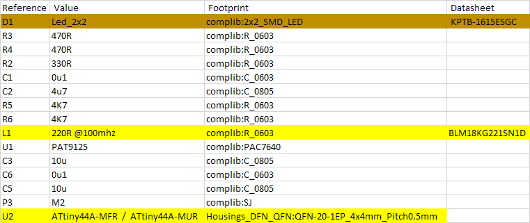
-
RE: Modified Laser Filament Monitor layoutposted in Filament Monitor
Got the PCBs ordered but so far not having much luck finding a BOM for the board. I guess if I can't find one I will just take apart the one that I have and use the parts from it.
-
RE: Modified Laser Filament Monitor layoutposted in Filament Monitor
Figured I would order them from JLCPCB. Got all the design rules to clear but now I am having a hard time figuring out exactly what parts to order. I figured there would be a BOM with part numbers but the BOM data does not have much information.
-
RE: Modified Laser Filament Monitor layoutposted in Filament Monitor
Oh wow that design rule check is a big help. It found some items that were too closet together.
-
Modified Laser Filament Monitor layoutposted in Filament Monitor
I am working on a new extruder design that I want to be able to incorporate the Laser Filament Monitor into it but the current board layout does not work for my needs. I have modified the KiCad files and wondered if there is anyone who knows what they are doing can take a look at them and make sure that I have the layout correct. I have never done any electrical board layouts before so I am very much a novice in this.
I have decreased the overall size of the board and moved the sensor closer to the edge of the board and removed the two pin connector points that were there.
Here are a few screen shots of what I have done.
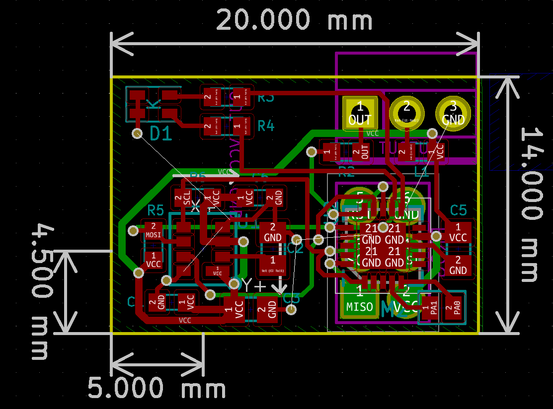
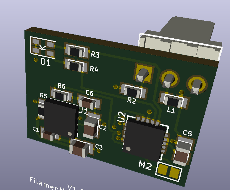
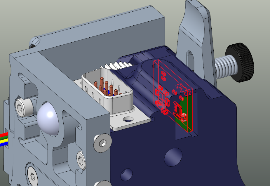
The 3D model shows the connector but I really just want the holes to solder the wires to.
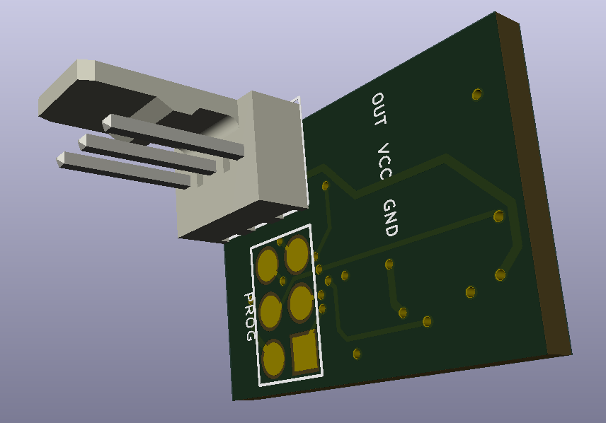
Here is a screen shot of where I am planning on putting the sensor in the extruder.
-
RE: Thermistor showing 2000posted in Duet Hardware and wiring
Success!!
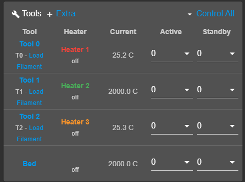
No heaters installed for Heater 2 or Bed yet so those are good.
-
RE: Thermistor showing 2000posted in Duet Hardware and wiring
Holy crap I found them.. And my wife thinks I keep too much junk from my 3D printer builds.. haha
-
RE: Thermistor showing 2000posted in Duet Hardware and wiring
@bearer Oh you know what.. you just sparked a memory from about 3 years ago. I had to replace the F1 fuse on this board before because of this issue. I checked it with my multi-meter and sure enough it is blown. I bought 5 of those last time... now I wonder where I put those.. haha
-
RE: Thermistor showing 2000posted in Duet Hardware and wiring
Oh sorry didn't notice that it cut the bottom of the meter off showing the setting. It was 10.4 kohm
Board version is 1.01 -
RE: Thermistor showing 2000posted in Duet Hardware and wiring
Like this? Sorry for the slightly blurry picture hard to hold the multi-meter and probes with one hand and take a picture with the other. The red probe is clipped to the left pin on T0 and the black probe is on the ground of the power in block.
Board version is 1.01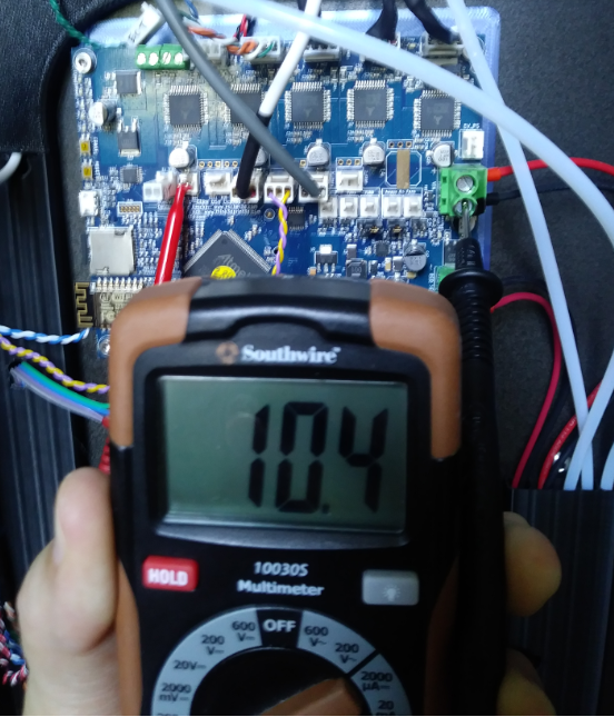
-
RE: Thermistor showing 2000posted in Duet Hardware and wiring
Small update
I decided to erase the firmware on this board and get everything to exactly the same on this board as my other one.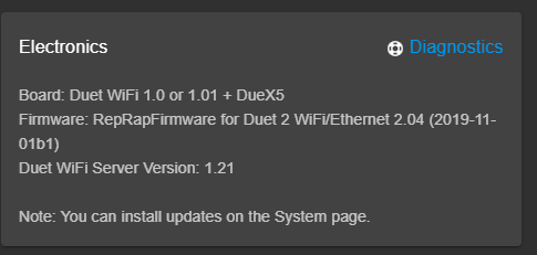

Still getting this. Heater 1 and 3 are the only ones with thermistors plugged into them at the moment but still shows 2000. Heater 3 is coming from the Duex5 which is a brand new board.
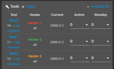
-
RE: Thermistor showing 2000posted in Duet Hardware and wiring
Not sure if this is helpful or not but here are some pictures of measuring the resistance on both boards, one that works and the one that doesn't
Working board:
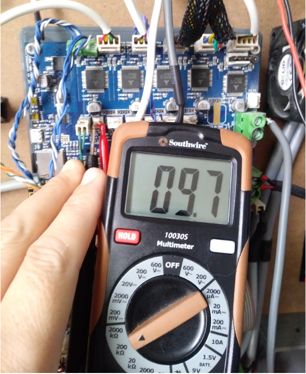
Not working board:
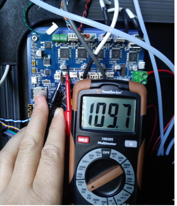
-
RE: Thermistor showing 2000posted in Duet Hardware and wiring
Yeah, it was showing a temperature and I was watching it rise from around 24 up to the 100 mark when it then went to heater fault. I should have looked in the DWC to see what the error was for but I was using the LCD panel on the printer at the time and did not think to check that before I reset the printer. After that it shows 2000 all the time.
I have tried two different thermistors on that board with the same results and tried those same thermistors on my other printer and they work fine.
Not seeing any apparent visible damage on the board but not sure where I should be looking.
I was thinking I could try using the thermistor inputs on the Duex5 but have not figured out how to set the tool/heater to use a different thermistor input.Is there some kind of test I can do on the board using a multi-meter?
-
Thermistor showing 2000posted in Duet Hardware and wiring
Need help diagnosing a thermistor problem I am having. I recently built a new printer using an existing Duet Wifi board that I had on hand and paired it with a new Duex5 board. I did all of the movement tests and all is working fine so I moved on to the hotend. Once I got my hotend installed I did a test to heat it up to 100c to make sure the fans were working but once it got heated up I got a heater fault and now the temperature reads 2000 which is usually when it is not detecting a thermistor. I tried a different thermistor in case I had a bad one with the same results so I moved that hotend over to my other printer and all reads fine.
Could this mean that this is a board issue?
If so, is there a way to check to verify there is an issue with my board?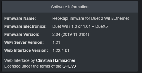
;Heaters*******************************************************************
M305 P0 S"BED" T100000 B4138 C0 ; Set thermistor
M143 H0 S110 ; Set temperature limit for heater 0 to 225CM305 P1 R4700 T100000 B4388 ; Set thermistor
M143 H1 S280 ; Set temperature limit for heater 1 to 300C
M307 H1 A452.5 C154.2 D6.2 V24.1 ; Set PID parameters for heater 1M305 P2 R4700 T100000 B4388 ; Set thermistor
M143 H2 S280 ; Set temperature limit for heater 2 to 300C
M307 H2 A527.5 C194.1 D8.9 V24.1 ; Set PID parameters for heater 2M305 P3 R4700 T100000 B4388 ; Set thermistor
M143 H3 S280 ; Set temperature limit for heater 3 to 300C
;M307 H3 A527.5 C194.1 D8.9 V24.1 ; Set PID parameters for heater 3;Tools*******************************************************************
M563 P0 D0 H1 F4 ; Define tool 0
G10 P0 R0 S0 ; Reset initial tool 0 active and standby temperatures to 0CM563 P1 D1 H2 F6 ; Define tool 1
G10 P1 R0 S0 ; Reset initial tool 1 active and standby temperatures to 0CM563 P2 D2 H3 F8 ; Define tool 1
G10 P1 R0 S0 ; Reset initial tool 1 active and standby temperatures to 0C;Fans*******************************************************************
;M106 P0 S0 I0 F500 H-1 ; UNUSED
M106 C"T0 FAN" P3 S1 I0 F500 H1 T70 ; T0 HE
M106 C"T0 LAY FAN" P4 S0 ; T0 PCF
M106 C"T1 FAN" P5 S1 I0 F500 H2 T70 ; T1 HE
M106 C"T1 LAY FAN" P6 S0 ; T1 PCF
M106 C"T2 FAN" P7 S1 I0 F500 H2 T70 ; T2 HE
M106 C"T2 LAY FAN" P8 S0 ; T2 PCF -
RE: Wire combining for tool headposted in Duet Hardware and wiring
@dc42 Currently the fans are 12v because I am using the Noctua 40mm fans and they do not come in 24v versions. Am I correct in thinking that the switching for the fans is done on the GND though?
@oliof I am currently using a 15 conductor cable and have the wires for the stepper coming out separate from the DB connector. I would prefer to have them in the connector but the DB15 connectors that I bought ware just so big that it really compromised the design intent of the extruder. Here is how I am currently running.
15 conductors:
4 for heater
2 for Thermistor
2 for HS Fan
2 for Part Fan
4 for Stepper
That comes to 14 of the 15 used. So now I have come up with a way to add a filament runout sensor built into the extruder just above the drive gears so I was thinking if I can use just one power wire for the fans that will free up one more wire to have two free.
Here are some pictures of my design. It is based on a bondtech BMG but is a highly modified design.With tool plate
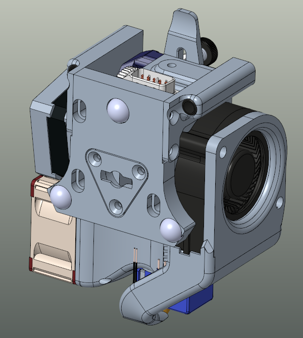
Tool plate removed you can see the DB9 connector
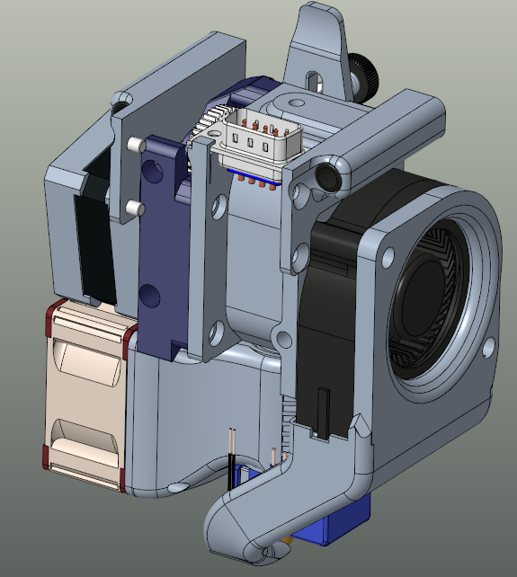
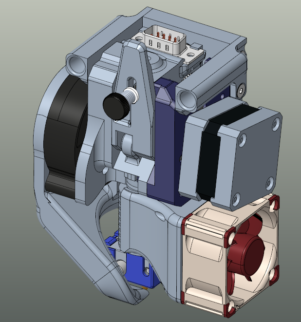
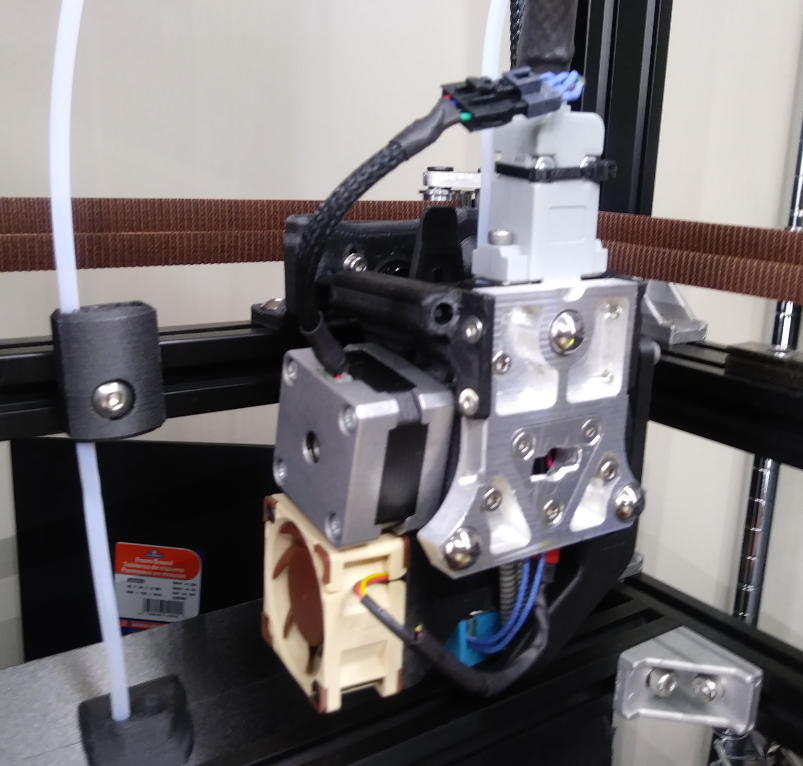
This is still in the prototype phase and have been refining the design over the past few months but I have been printing with no issues now for about two months and been able to print PC with no jams or heat creep.
The tool mounting and locking system is based on a design by PoofJunior over on Thingiverse that he did for his Jubilee printer.