• Tags
  • Documentation
  • Order
  • Register
  • Login
Duet3D Logo Duet3D
  • Tags
  • Documentation
  • Order
  • Register
  • Login
  1. Home
  2. Acid
  3. Posts
  • Profile
  • Following 0
  • Followers 0
  • Topics 6
  • Posts 17
  • Best 3
  • Controversial 0
  • Groups 0

Posts made by Acid

  • Add option to M291 to display a popup message on the LCD only

    Hi, I've been looking into the option to display a message on my LCD panel (using an 12864 LCD).

    Right now I'm using M291 but no matter the option used, it still also displays an overlay on my DWC. This gets in the way when I am running a job, but at the same time, am monitoring some things in the DWC via my browser.

    I know it's a simple case of waiting or clicking to make the message disappear in DWC, but I wish there was an option to let the message display on LCD only.

    Right now the moment when this bugs me the most is when I do an auto-calibration on my Delta printer and I want to briefly display the deviation on the LCD via this message:
    M291 P{move.calibration.final.deviation} ^ "mm" S1

    It shows up beautifully on the LCD, but it also overlays the entire DWC screen.

    After this I tried all options of M118 and I tried M117, but these messages didn't show up on the LCD screen at all.

    This question was first discussed on a discord I'm in, but nobody knew about a way around this. Hence this feature request.

    In all honestly it probably doesn't happen often that someone would want to use this feature this way, and it might not even be possible due to firmware/DWC archicture, but I thought it was interesting enough to share and ask.

    posted in Firmware wishlist
    undefined
    Acid
    22 Mar 2023, 16:17
  • RE: Delta specific acceleration and jerk sane tuning?

    @Phaedrux said in Delta specific acceleration and jerk sane tuning?:

    Those look like sane starting values.

    You can live tune the values by sending the commands during a print. To make that a bit easier there's a pack of tuning macros here: https://forum.duet3d.com/topic/6181/tuning-macros-menus-accel-jerk-retraction-pressure-advance?_=1678993843407

    Yes, that looks just like what the doctor ordered. I'm almost home and will start working on it immediately.

    I'm pretty sure my machine can go a lot higher. Your tuning macros will be used as an inspiration but I'll probably customize them a bit.

    Thanks for sharing!

    posted in Tuning and tweaking
    undefined
    Acid
    17 Mar 2023, 15:38
  • Delta specific acceleration and jerk sane tuning?

    Hi!

    This past week I've been tuning my newly finished Delta printer. Most of it is working correctly now, but I am looking into tuning feeds and speeds to allow the machine to operate a little faster.

    My aim is to stay within the max speeds that allow me to stay in Stealthchop mode (extruder Orbiter v2 in bowden modus runs on spreadcycle), however, my extruder can't keep up with the max speed, so this is the deciding factor.

    For non-printing moves I am able to reach 120mm/s without the drivers switching over to spreadcycle.

    These are my current values:

    M566 X1200 Y1200 Z1200 E700 	       		   ; set maximum instantaneous speed changes (mm/min)
    M203 X7200 Y7200 Z7200 E6000        		   ; set maximum speeds (mm/min)
    M201 X4500 Y4500 Z4500 E4500         		   ; set accelerations (mm/s^2)
    

    I intentionally limited the maximum speeds at 7200mm/min which translates to 120mm/s to make sure the machine doesn't hit the threshold.

    The thing is that most topics I could find were about tuning these values for bedslingers, and since a Delta spec has a lot lower moving mass, I'm assuming that jerk and acceleration could be tuned a lot higher. I find it hard to get a 'feel' for how I can tune jerk.

    What are good (sane) values to start from? And are there recommended guides that can help me progress from there to further tune it?

    posted in Tuning and tweaking
    undefined
    Acid
    16 Mar 2023, 14:45
  • [RRF 3.5b2] Unload macro broken, but works when manually sent

    Hi,

    I'm trying to get my filament unload macro to work but the machine simply doesn't want to do what it's told.

    This is the script:

    ; set extruder PREHEAT temp
    M568 R130 S245      ; set standby and active temperatures for active tool
    M568 A1             ; set tool to standby temp for filament switch
    M116 H1             ; Wait for temp to be reached
    
    ; Step 1 > Pause > move to a spot center-front for easy access
    G28				    ; Home printer
    G91             	; relative positioning
    G1 Z-20 F7200      	; lower Z by 5mm
    G90             	; absolute positioning
    G1 X0 Y-110	F6000	; and move nozzle towards the user
    
    ; Step 2 > Ask user to intervene
    ;M291 P"Filament swap sequence started, press okay when the hotend has reached 130 degrees Celsius" R"Filament swap initiated" ;S2 ; R is title!
    
    ; Step 3 > After checking you click okay and it starts reversing filament
    M302 P1         ; Allow cold extrusion
    M83             ; Set extruder to relative mode
    G1 E-620 F3000  ; Unwind the filament 620mm
    M568 A0			; and turn off tool
    M302 P0         ; Unallow cold extrusion
    
    ; Step 4 > Notify user and offer option to place new filament
    ;M291 P"Remove remaining filament and click OK" R"Filament unload done" S2
    

    The issue is that when I manually send (while hotend temp is 130C):
    M302 P1

    and then
    G1 E-620 F3000 ; Unwind the filament 620mm

    It perfectly unloads filament.

    First I had the message boxes in there, but I read in another topic from the previous beta (https://forum.duet3d.com/topic/30929/3-5-b1-loading-filament-via-dwc-does-not-work) that these could cause issues. So I deactivated those lines but still it doesn't want to work.

    Are there any known issues with this type of script in 3.5b2?

    Edit:
    Excuse me, it appears this issue has been fixed by DC42:
    https://github.com/Duet3D/RepRapFirmware/commit/94b33ae5404cdb67a69b51ff8099a596dfbb3940

    I'm assuming this fix will trickle down into the next beta.

    0 dc42 committed 13 Feb 2023, 22:04 to Duet3D/RepRapFirmware
    Fix for allowing cold extrusion
    posted in Beta Firmware
    undefined
    Acid
    14 Mar 2023, 12:49
  • RE: Wrap text on 12864 displays - 3.5b2

    @OwenD said in Wrap text on 12864 displays - 3.5b2:

    @jay_s_uk
    I'm not near a printer
    I don't think you can, but maybe try concatenation of a new line in the message?
    M291 S"this is line 1" ^ \n ^ "this is line 2"

    I'd vote for it as a firmware addition.

    Hi OwenD, I tried this out but for me it only shows line one with the example. Also, S should be P 😉

    Ran into the same issue today where my filament unload script worked on one printer, but the other machine only shows one line of text, which is then clipped instead of concatenated.

    Would there be anything else we could try?

    posted in Beta Firmware
    undefined
    Acid
    13 Mar 2023, 21:55
  • RE: [Solved][Delta] Precision Piezo issues

    I just wanted to add that I have once again redesigned part of the bed and replaced the cables with shielded and grounded cables and now the leveling process is truly painless.

    The only issue being that I might've set the sensitivity too high, so with long probing sessions it might pick up a false reading, but to minimize issues I have redesigned the probing pattern and limited the amount of points to 9 instead of 18. 18 points is overkill. And with 9 points I get flawless results:
    9630a4d6-5588-4391-bd7a-46e590b58071-image.png

    Because I have seen a lot of topics about this that do not always explain the solution I will soon dedicate some of my time to do a showcase of my machine and explain in-depth how I have tackled some of the problems that came with the piezo leveling setup. I'll also try to go into the program I designed to generate the probing points for the auto calibration.

    On top of that this machine uses three levers that function as a proxy to the endstops. It's a flexible joint lever which might be of interest to some users here. I wanted a lever so I could reach the maximum height on this machine, since placing the endstop between the top vertexes and the MGN12 cart would cause me to lose around 20mm of print height. Now the lever sits near the top and triggers the endstop when the cart hits the lever. In other words, the endstop has its button pointing up, so it is reversed to traditional Delta endstop positions.

    A printer is never finished, it's alive.

    Thanks again for all the help.

    posted in Tuning and tweaking
    undefined
    Acid
    13 Mar 2023, 18:36
  • RE: [Solved][Delta] Precision Piezo issues

    @infiniteloop said in [Delta] Precision Piezo issues:

    @Acid

    I actually am using it in analog mode. I think I've run out of options…

    The ADC converters I know of in MCUs are relatively slow, for example, the sampling frequency of an Arduino ADC at 10 bit resolution is specified with 9.6 Hz. That means: you get about 10 measures per second. Sure, the Duets are much more responsive, but they too need a finite time for a sample. If you evaluate the data points with a script, the runtime of the script comes on top. All this accounts for a rather limited resolution over time.

    I use a probe with a light sensor in analog mode on a Duet 2. In oder to get some kind of precision readings, I had to reduce the probing speed to 200 (F parameter of M558). Note that I use the generic setup with M558, just one sensor, no (interpreted) script involved. So I strongly recommend to try a probing speed way below your F500.

    Now there are two things I can think of trying, the first one will be to isolate all the sensor wires as it looks like there is interference that is sending false readings, however I have no idea how to make isolated wires in the first place anyway.

    You can either cannibalise shielded USB cables (not all of them are shielded), or use audio input cables - those for microphones and other sources with low signal strength are always shielded.

    Thanks for your tips. I have seemed to solve the problem by switching to Digital Output on the PrecisionPiezo PCB and then tuning the VR2 setting on the PCB. It's not perfect, but it's close enough.

    After this I finally activated my DIY oscilloscope that I built years ago and measured the Analog signal and it only fluctuates a few mV when triggered, so the issue is probably with the Analog signal coming from the PrecisionPiezo PCB.

    With the fixed setup I now achieve this autocalibration measurement first try:
    Calibrated 8 factors using 18 points, (mean, deviation) before (-0.120, 0.029) after (0.000, 0.022) Auto calibration successful, deviation 0.022mm

    Normally it had to probe at least 5 or 6 times before it would even start, and I had to raise the tolerances. I can't imagine all that pounding of the hotend onto the bed has been good to my machine so I hope that nothing got damaged. Due to issues I had to remake the diagonal rods three!!! times and I was getting really demotivated 😰 But somehow I pulled through and managed to finish the build.

    Is there some place where we can share out DIY machines in some kind of showcase subforum?

    posted in Tuning and tweaking
    undefined
    Acid
    2 Mar 2023, 18:20
  • RE: [Solved][Delta] Precision Piezo issues

    @cosmowave said in [Delta] Precision Piezo issues:

    @Acid Eventually you can try to use the piezos in analog mode.
    Perhaps it helps to find the root cause.

    Hi, I actually am using it in analog mode. I think I've run out of options and will try to replace the board with another one to see if this improves anything.. Sadly.

    I noticed the analog input doesn't register the values correctly so I am suspecting the ADC on my current board might be malfunctioning somehow. It worked correctly before, and there is no issue with interference of any type. In DWC the readings do not correctly update, and despite using it in analog mode, it looks like it's in '0/1' mode, as if it only registers 0 or 1000, and it only registers 1000 if I punch the bed plate.

    A short update:
    It seems that when using the PCB in digital mode, it performs well, but it gets negative readings sometimes. I have tried adusting the sensitivity, but that makes it so that the nozzle pushes down the bed.

    Now there are two things I can think of trying, the first one will be to isolate all the sensor wires as it looks like there is interference that is sending false readings, however I have no idea how to make isolated wires in the first place anyway.

    The other option for me would be to shorten the wires. Do the precisionpiezo wires have to all be the same length when using an underbed piezo setup?

    posted in Tuning and tweaking
    undefined
    Acid
    2 Mar 2023, 12:48
  • RE: [Solved][Delta] Precision Piezo issues

    @cosmowave said in [Delta] Precision Piezo issues:

    @Acid Are you sure, that every of the three piezo is working correctly? It can be, that two triggers with pushing and one with releasing.

    Hello, yes, I've also tested them individually. I went through every possible option and I'm thinking the issue now lies with how my controller interprets the signal from the PrecisionPiezo PCB.

    posted in Tuning and tweaking
    undefined
    Acid
    2 Mar 2023, 11:47
  • [Solved][Delta] Precision Piezo issues

    Hi everyone,

    The past two weeks I've dedicated to finishing my Delta build running RRF, and using Precision Piezo piezo's under the bed for probing. I'm using the universal v2.85 board:
    https://www.precisionpiezo.co.uk/product-page/universal-piezo-z-probe-pcb-v2-x-for-1-2-3-or-more-piezos

    I've been using this setup for a long time and it used to work well before. I've noticed that my old setup could be improved a bit as during probing I found the nozzle still pushed quite hard into the bed so I started tweaking the system and found out my issues work somewhat counter-intuitive.

    First I raised the plunge speed which seemed to help get a harder hit which triggered better. Then I discovered that the screws that held my bed would change in tightness depending on if the bed was heated or not so I redesigned the whole bed mount system to use a three-point coupling system:
    4ffb965e-e493-4df4-82f5-5503170f468f-image.png

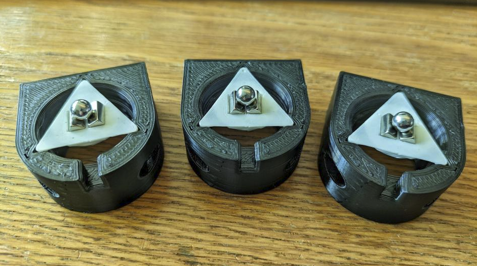
    The bed has mounts that connect to the ball magnets and the white triangles have a pointy bottom that pushes in the piezo discs. If the bed heats up, the balls can move outwards, sliding over the block magnets, this makes sure the bed can freely expand while keeping the bed in place.

    This is the most sensitive system I've been able to build so far, it literally triggers from the lightest taps (see https://www.youtube.com/watch?v=QssthZMF7tU). I've also been able to probe with it quite well, but still somehow the hotend pushes the bed in, making it deflect between 0.5 and 1 mm.

    M558 P5 R0 C"!probe" H2 F7200 T7200 B1
    G31 P100 X0 Y0 Z-0.266 S0 
    

    These settings seemed to work okay, but a lot of the time I now can't get the probe to get a good enough minimum deviation to start a print.

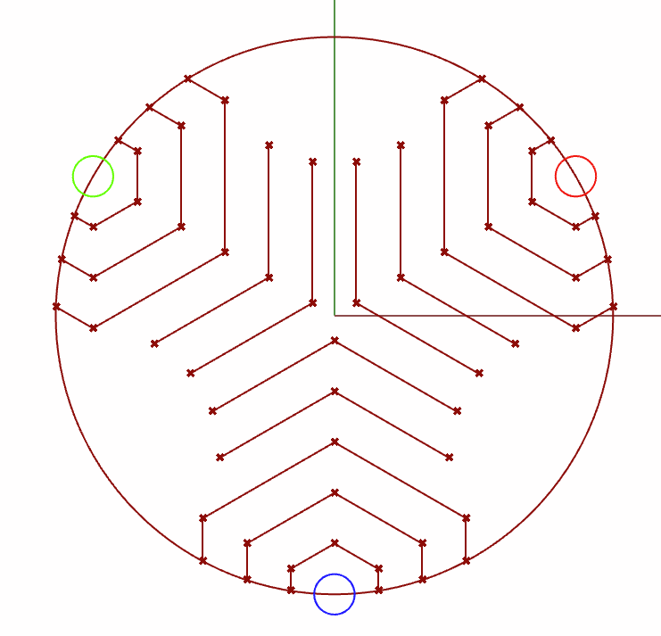
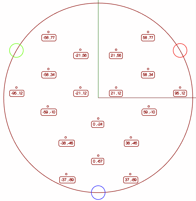
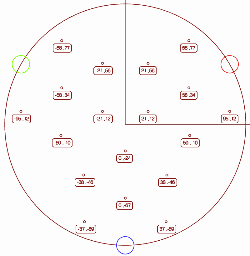
    I am using the iterative probing script to probe the bed in the most sensitive areas possible to get the best readings. I designed a program that auto-generates points in places where the piezo probes get the strongest signal (working demo here) :

    3d1eadc9-bfce-4b72-9666-881f2104eaab-image.png

    It ran alright, this is a reasonably working probing example:
    https://www.youtube.com/shorts/eEXjATJ_640

    Still, I couldn't get it to work as good as before. It used to be really gentle and precise, but my old machine used plastic vertexes, had delta rods with lots of play, etc. My new machine has alu vertexes, thick extrusions, precision rods, better bed mounts, etc etc. What could be the problem?

    So I did some more reading, when I found this quote from a user over in the piezo probe discussion:
    @BlueDust said in Precision Piezo z probes guide for duet users reference:

    @en_passant
    Try swapping the wires from the Piezo Sensor to the Piezo motherboard.

    If the Piezo triggers on press, its correct, but if it triggers on release try swapping the sensor wires and see if that fixes it.

    I did a check, and indeed, the piezo didn't register anything if I pushed in my bed gently and only triggered upon release. So I did what seemed logical and reversed the wires from each piezo disc. This resulted in a direct trigger whenever the bed was pushed in, and the system seemed even more sensitive than before.

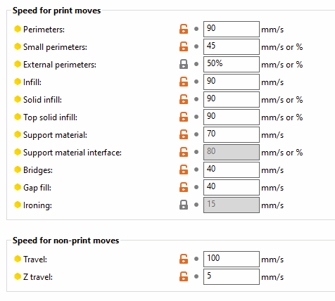
    I also tried lowering the probe speed to:

    M558 P5 R0 C"!probe" H2 F500 T7200 B1
    

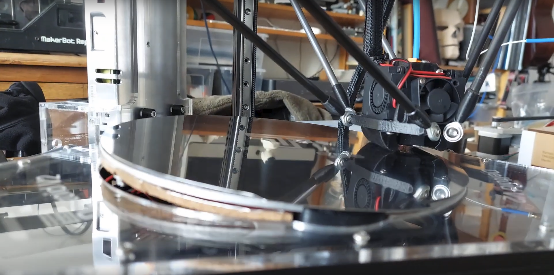
    Howeverrrrrr, despite having a super sensitive probing setup and slower probing, the nozzle now literally pushes so hard into the bed that one side flips up. This takes an extreme amount of force to to by hand, so it's clear that the piezo setup is not working well.

    Here's a video:
    https://www.youtube.com/watch?v=QssthZMF7tU

    Still from the video:
    1cada7b4-fba7-416f-a73f-f887f210e5d9-image.png

    So in short:

    • My new probing setup is the most sensitive I've been able to craft to this day
    • With the probes in the "correct orientation" (according to another user) it works worse
    • Help

    Here's a link where I explain how I made the probing point cloud:
    https://forum.duet3d.com/post/308768

    This is my bed.g:

    ; Auto calibration routine for large delta printer
    M561                    ; clear any bed transform
    
    ; If the printer hasn't been homed, home it
    if !move.axes[0].homed || !move.axes[1].homed || !move.axes[2].homed
      G28
    
    ; Probe the bed and do auto calibration
    G1 X0 Y140 Z10 F10000        ; go to just above the first probe point
    while true
      if iterations = 10
        abort "Too many auto calibration attempts"
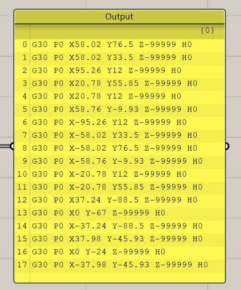
      G30 P0 X95.26 Y12 Z-99999 H0
      if result != 0
        continue
      G30 P1 X58.76 Y-9.93 Z-99999 H0
      if result != 0
        continue
      G30 P2 X37.98 Y-45.93 Z-99999 H0
      if result != 0
        continue
      G30 P3 X37.24 Y-88.5 Z-99999 H0
      if result != 0
        continue
      G30 P4 X0 Y-67 Z-99999 H0
      if result != 0
        continue
      G30 P5 X0 Y-24 Z-99999 H0
      if result != 0
        continue
      G30 P6 X-20.78 Y12 Z-99999 H0
      if result != 0
        continue
      G30 P7 X20.78 Y12 Z-99999 H0
      if result != 0
        continue
      G30 P8 X58.02 Y33.5 Z-99999 H0
      if result != 0
        continue
      G30 P9 X58.02 Y76.5 Z-99999 H0
      if result != 0
        continue
      G30 P10 X20.78 Y55.85 Z-99999 H0
      if result != 0
        continue
      G30 P11 X-20.78 Y55.85 Z-99999 H0
      if result != 0
        continue
      G30 P12 X-58.02 Y76.5 Z-99999 H0
      if result != 0
        continue
      G30 P13 X-58.02 Y33.5 Z-99999 H0
      if result != 0
        continue
      G30 P14 X-95.26 Y12 Z-99999 H0
      if result != 0
        continue
      G30 P15 X-58.76 Y-9.93 Z-99999 H0
      if result != 0
        continue
      G30 P16 X-37.98 Y-45.93 Z-99999 H0
      if result != 0
        continue
      G30 P17 X-37.24 Y-88.5 Z-99999 H0
      if result != 0
        continue
      G30 P15 X0 Y0 Z-99999 S8
      if result != 0
        continue
      if move.calibration.initial.deviation <= 0.04
        break
      echo "Repeating calibration because deviation is too high (" ^ move.calibration.initial.deviation ^ "mm)"
    ; end loop
    echo "Auto calibration successful, deviation", move.calibration.final.deviation ^ "mm"
    G1 X0 Y0 Z150 F10000                ; get the head out of the way
    

    Edit:
    After doing some more experimenting, I've found out that there seems to be an issue with my board not detecting a trigger correctly. The PrecisionPiezo PCB LED indicates that it is triggered but RRF doesn't stop probing movement when executing a G30.

    Second edit:
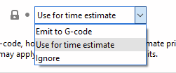
    This issue has been solved by switching to Digital Output on the PrecisionPiezo PCB. The Analog signal doesn't seem to work correctly and barely puts out a strong enough signal to be read.

    posted in Tuning and tweaking
    undefined
    Acid
    2 Mar 2023, 09:27
  • RE: Precision Piezo z probes guide for duet users reference

    @BlueDust said in Precision Piezo z probes guide for duet users reference:

    @en_passant
    Try swapping the wires from the Piezo Sensor to the Piezo motherboard.

    If the Piezo triggers on press, its correct, but if it triggers on release try swapping the sensor wires and see if that fixes it.

    I feel like I'm endlessly trying to get my underbed piezo's work. I'm using the Precision Piezo – Piezo Z-Probe Universal Kit V2.75

    I'm using analog settings and have my bed setup in such a way that the piezo is supported along the edged and another part presses into the center.

    It worked okay before, I have tuned them to be as sensitive as I can get them, when I read the comment about reversing polarity of the discs I was intrigued and it appeared that my discs would also only get a signal upon release and not upon depression of the bed.

    So I turned around the wires for the discs and it actually made it way worse. Now the nozzle has just been pushing into the bed so hard that it deformed and damaged my printing surface.

    Reversing the polarity again back to how I think it should be, the probing works a lot better but still it tends to push hard into the bed, just not as hard as to damage the surface.

    There once was a time where my setup worked better, having a near-hair trigger. I would like to find that again.

    Are there other things I can try such as tuning the dive speed for each probe? I have seen some people use this underbed piezo setup with great success and it looks like their probing scheme moves much faster than mine. I'm thinking a faster dive speed might also help with getting better readings.

    These are my current settings:

    M558 P5 R1 C"!probe" H2 F3000 T6000 B1         ; set Z probe type to effector and the dive height + speeds
    G31 P100 X0 Y0 Z-0.216 S0
    

    I also find it hard to get an exact adjustment on VR2, it's either triggered by me tapping the frame and only a fraction of a turn, and it barely registers tapping on the bed.

    Update:
    Just wanted to add that I have been tuning the feedrates for probing a bit and raising the speeds have helped make it more precise.

    This is what I got now:
    https://youtube.com/shorts/eEXjATJ_640

    The only issue being that the machine doesn't seem to print perfect first layers across the bed. Would a Delta printer require a mesh from G29? The bed is perfectly flat (alu bed), even when heated.

    I'm thinking any typenof distortion is still caused by the auto calibration despite consistently hitting sub 0.03 deviation as can be seen in the video.

    posted in Third-party add-ons
    undefined
    Acid
    25 Feb 2023, 14:03
  • RE: Precision Piezo Delta bed mount

    @Nxt-1

    Well drawn explanation of the piezo sensitivity!

    Sorry for necroing this thread, but your drawing inspired me to design a program that can generate a point cloud for probing, that avoids the points near the towers and prefers the points near the underbed piezo's.

    Sadly it's made in Grasshopper so I can't share it as a script or executable, but maybe this could be inspiring to someone.

    I just finished my DIY Delta printer today and I noticed that the probing wasn't that great across the bed so I wanted to see if I could fix that somehow. Assuming my bed is flat enough, I came up with this, where the colored circles are the piezo locations:

    Example with lines drawn:
    9c8f3237-91f5-41e9-8df4-8e158ddf8a8a-image.png

    Outermost points culled and I tweaked the amount of points a little bit (and the point data is rounded to whole numbers):
    f7aad29a-4642-4322-953f-6f08c6cd600d-image.png

    And this is the output point list that can now manually turned into a list for the reiterative probing sequence for example (with the point data rounded to two decimals):
    4d5e58f3-fc33-4f0a-b941-af7d6e556de2-image.png

    This data can be changed on the fly, so I can see what the probing pattern will look like live without having to first run a script, it's live:
    https://youtu.be/0ofXqwViaMc

    I hope this could serve as an inspiration to someone and if you have ideas of a good type of point distribution I'd love to hear your ideas.

    I have yet to try out this set of points but it's kinda late now so I'll do that tomorrow when I'm sharp and present again.

    Just a small update on this reply, which I might turn into a post later on if anyone thinks it deserves its own post:

    The results are in, initially it had quite a big deviation, but the second probing sequence was an immediate hit:
    Calibrated 8 factors using 18 points, (mean, deviation) before (-0.009, 0.034) after (0.000, 0.022) Auto calibration successful, deviation 0.022mm

    I also incorporated a point sorting algorithm. Before the point list was random, causing long travel times during probing, but now it's just moving from one point to the next closest point making this a painless probing sequence.

    posted in Using Duet Controllers
    Acidundefined
    Acid
    23 Feb 2023, 21:42
  • RE: Filament runout script doesn't work

    @dc42

    Thanks a lot for the suggestions, I have added this, and I also added some more variables to make sure a the filament runout script cannot be run when the print hasn't started yet because I had the issue that it would start to retract when I restarted the printer without any filament present.

    So my filament-error.g looks like this now:

    ; first check that we are not currently in an error state and the switch has been toggled again.
    if (global.filamentDistance !=0) || (state.status != "processing")
    	echo "Filament sensor triggered, but no print in progress.  No action taken"
    	M99 ; exit macro
    
    set global.inFilamentError=true
    M25 ; pause print
    set global.inFilamentError=false
    
    ; Step 1 > Pause > move to a spot center-front for easy access
    G60 S0          ; Save position to slot 0
    G1 E-10 F3600   ; retract 10mm of filament
    M568 A1         ; set tool to standby temp
    G91             ; relative positioning
    G1 Z5 F360      ; lift Z by 5mm
    G90             ; absolute positioning
    G1 X1 Y75 F3000	; Move out of the way
    
    ; Step 2 > Ask user to intervene
    M291 P"Filament runout detected, proceed?" R"Filament out" S2
    
    ; Step 3 > After checking you click okay and it starts reversing filament
    M302 P1         ; Allow cold extrusion
    G1 E-520 F3000  ; Unwind the filament 400mm
    
    ; Step 4 > Notify user and offer option to place new filament
    M291 P"Remove remaining filament, insert new filament and continue" R"Insert new filament" S2
    G1 E480 F2000   ; Load filament 480mm fast
    G1 E20 F750     ; Load the last bit a little slower
    
    ; Step 5 > heatup hotend back to extruding temperatures and extrude a little extra to prime the nozzle
    M568 A2         ; Set active temperature of the active tool
    M116            ; wait until hotend reaches set temperature
    M302 P0         ; Disable cold extrusion
    G1 E20 F60      ; Prime the nozzle a little bit
    M291 P"Remove the extruded string and click to continue" R"Printer ready" S2
    
    ; Step 6 > Resume the print
    G1 R1 X0 Y0 Z5 F36000   ; go to 5mm above position of the last print move
    G1 R1 X0 Y0 Z0          ; go back to the last print move
    M24 ; resume print
    

    Going to give this a try!

    posted in Filament Monitor
    Acidundefined
    Acid
    27 Jan 2023, 20:30
  • Filament runout script doesn't work

    Hi,

    I've made my own filament sensor using an optical sensor and a proxy that blocks this sensor whenever the filament is loaded. I've declared its pins in the config.g and tested it and can confirm this part is working.

    However, when I cut the filament manually to test my script, the machine moves to the designated location G1 X1 Y75 F3000 but it doesn't stop the print. Instead it goes back to where it was printing and continues to print.

    It then shows a popup on my LCD screen from the first M291 and when I press 'ok' the extruder starts to unwind filament WHILE the machine just keeps on printing as if nothing happened.

    I'm running on 3.4.4 so pause isn't automatically triggered.

    I specifically don't want to run pause.g because that has commands in it that conflict with my filament-error.g

    I looked at other examples by other users and examples found on the forum and decided to make my own script as I didn't want to make it as complicated as some of the examples and I wanted to keep it within my understanding so that if an issue came up I could solve it myself.

    It seems I may have forgotten to use M25 to pause and M24 to resume, but I haven't found this in scripts by others, so I'm wondering what may be my problem.

    This is the source of filament-error.g

    ; Step 1 > Pause > move to a spot center-front for easy access
    G60 S0          ; Save position to slot 0
    G1 E-10 F3600   ; retract 10mm of filament
    M568 A1         ; set tool to standby temp
    G91             ; relative positioning
    G1 Z5 F360      ; lift Z by 5mm
    G90             ; absolute positioning
    G1 X1 Y75 F3000	; Move out of the way
    
    ; Step 2 > Ask user to intervene
    M291 P"Filament runout detected, proceed?" R"Filament out" S2
    
    ; Step 3 > After checking you click okay and it starts reversing filament
    M302 P1         ; Allow cold extrusion
    G1 E-520 F3000  ; Unwind the filament 400mm
    
    ; Step 4 > Notify user and offer option to place new filament
    M291 P"Remove remaining filament, insert new filament and continue" R"Insert new filament" S2
    G1 E480 F2000   ; Load filament 480mm fast
    G1 E20 F750     ; Load the last bit a little slower
    
    ; Step 5 > heatup hotend back to extruding temperatures and extrude a little extra to prime the nozzle
    M568 A2         ; Set active temperature of the active tool
    M116            ; wait until hotend reaches set temperature
    M302 P0         ; Disable cold extrusion
    G1 E20 F60      ; Prime the nozzle a little bit
    M291 P"Remove the extruded string and click to continue" R"Printer ready" S2
    
    ; Step 6 > Resume the print
    G1 R1 X0 Y0 Z5 F36000   ; go to 5mm above position of the last print move
    G1 R1 X0 Y0 Z0          ; go back to the last print move
    

    Maybe the issue is clear to the advanced user, maybe there are more issues in my script. I'm pretty new to RRF, have my machine up and running for a while now without issues, but writing files like these are still a bit difficult for me.

    Thanks for your time.

    posted in Filament Monitor
    Acidundefined
    Acid
    27 Jan 2023, 15:46
  • RE: Why the slowdown?

    @Phaedrux said in Why the slowdown?:

    This is pretty common with the orbiter and other small drive and remote extruders.

    You may need to experiment with your jerk and acceleration setting for all axis to find a happy medium.

    For instance, your jerk on XYE is very low, but your acceleration is very high.

    Give these settings a try.

    M566 X700 Y700 Z60 E900 	       ; set maximum instantaneous speed changes (mm/min)
    M203 X18000 Y18000 Z600 E6000      ; set maximum speeds (mm/min)
    M201 X2000 Y2000 Z200 E2000         ; set accelerations (mm/s^2)
    

    Thanks for the suggestion, I'm giving it a try now. Seems like it's going a lot faster already. The only thing is that the extruder is giving off a distinct whine at these speeds but only due to PA. On longer moves the extruder is inaudible.

    I guess lowering extruder jerk a little might help with the whine?

    The official website for Orbiter v2 recommends a max of 600mm/min for E-jerk. Can I change this value during a print, or actually is it possible to change any of the M566, M203 and M201 values during a print via DWC?

    Edit:
    I just read that stealthchop is recommended to be turned off for the Orbiter v2, yet I see a lot of people run it with stealthchop. Does this have to do with the crossover speed where it transitions from stealthchop to spreadcycle?

    Edit #2:
    Okay, I tried it and it turns out I can even tune these settings on the fly which makes tuning a lot easier. I didn't know this before!

    The settings I'm running with now are:

    M566 X700 Y700 Z60 E700 	       			   ; set maximum instantaneous speed changes (mm/min)
    M203 X18000 Y18000 Z600 E6000      			   ; set maximum speeds (mm/min)
    M201 X2000 Y2000 Z200 E4500         	        	   ; set accelerations (mm/s^2)
    

    These speeds are still somewhat noisy, but I don't want to lower them any further as that will increase print times. Trying a benchy now to see how long it takes. I do see that with the higher print speeds my part cooling fan isn't fast enough. Also, sometimes the extruder sounds like it's doing a very fast retraction, like a zipper that you pull really fast. It's almost as if it skips steps, but I can't quite make out if that it true or not. Is there any smart way to check if it skips steps? I'm assuming since I now run the motor in stealthchop it doesn't register a stall because the signal is too noisy for the TMC2209 to distinguish the move noise from a stall back-EMF or however it does that (I'm not yet that familiar with the techniques it uses to detect stalls).

    It's now also time to probably start tuning from the beginning again since I changed a bunch of parameters and I also still need to find a good way to tune retraction.

    One other thing I'd like to start tuning is extrusion width. Since the Orbiter v2 should be able to handle some pressure and I'm currently extruding at 0.6mm like a good boy, I'm thinking to take this a bit higher. My goal was faster prints, so increasing the extrusion width will help with that as well. I understand that 0.72mm (120%) is a good amount for the 0.6mm nozzle.

    Would my current speed/jerk settings need to be tuned further when changing the extrusion width, or will this be less of an issue?

    posted in Tuning and tweaking
    Acidundefined
    Acid
    23 Dec 2022, 12:43
  • RE: Why the slowdown?

    @dc42 said in Why the slowdown?:

    @Acid please check that PrusaSlicer has not inserted M201 or M203 commands into the GCode file that you are trying to print. It tends to do that if you are not careful. Also look out for M204 commands, which limit the printing and travel accelerations - which is OK if that is what you wanted for that print.

    Hi, thanks for the hint. This should not be possible since this option was chosen:
    5ddbaf47-e66d-420d-a31b-68c437295ce4-image.png

    But I checked it just to be sure (you never know). Luckily that wasn't the issue.

    I did some more testing, like changing the PA settings (by setting it to 0) during a print and that made the print speed up a lot so I think the issue is with PA.

    From what I gather the only way to speed up the printer is to raise the extruder jerk, but this becomes problematic because the extruder starts making a lot of noise when I raise the jerk and accel settings for the extruder. I don't want to damage the extruder.

    My previous extruder could go a lot higher with jerk and accel and still wouldn't produce nearly as much noise but it was also less powerful so that's why I got an Orbiter. I've seen so many people on youtube with RRF that run their printer very fast with an Orbiter v2. Can it be that they are running without pressure advance and that I have unrealistic expectations?

    I just don't understand how E-jerk in combination lowers the print speed by so much. It's logical that it has influence on the print speed because it takes control of the extrusion. Are there other things I can try?

    posted in Tuning and tweaking
    Acidundefined
    Acid
    22 Dec 2022, 19:54
  • Why the slowdown?

    Hi all,

    I've been tuning my machine for a while and I can't seem to figure out why my machine is a lot slower since moving from Marlin to RRF.

    Usually, on Marlin, when slicing my prints with PrusaSlicer and running it, would result in around correct slicing estimates. It normally only took one or two minutes longer than the slicer had ancitipated.

    Since I moved to RRF with around the same or faster settings, my prints take around more than twice the time estimate and this is absolutely driving me nuts. Especially since I also moved to a 0.6mm nozzle (previously had a 0.4mm nozzle equipped).

    These are the values currently in my config.g:

    M566 X350.00 Y350.00 Z50.00 E300.00 	       ; set maximum instantaneous speed changes (mm/min)
    M203 X18000.00 Y18000.00 Z300.00 E6500.00      ; set maximum speeds (mm/min)
    M201 X4000.00 Y4000.00 Z20.00 E4000.00         ; set accelerations (mm/s^2)
    

    And these are my PS values for printing PETG:
    047c430e-077e-4f44-8155-e4c625821da4-image.png

    I'm using an Orbiter v2 extruder with a bowden setup and I use both PA and IS:
    IS is using ZVD at 40Hz
    PA is set to 1.35

    I've been trying to tune it a bit in the past two weeks but I have not been able to find the reason why the estimates are so off. I also have put my RRF speed settings into PS in order to help it make a better time estimate.

    En example would be that a simple benchy would take 38 minutes to print according to PS. In reality after 57 minutes, the print is only at 58% finished. This would mean that the print time is around 100 minutes total. This is an increase of roughly 260% of the estimates print time. And to be honest, isn't 100 minutes for a benchy with 0.6 nozzle and an Orbiter v2 extruder a little slow?

    The sole reason why I went through all the trouble of converting to IS, PA, 0.6mm nozzle and a better extruder was to get better print times. But instead the print times have increased 'super drastically'. Maybe I'm missing something in my tuning that is causing this slowdown and I can't seem to find it on my own so I am asking the community to think along with me as I don't know what else to do.

    The machine was tuned with this guide and is otherwise working well: https://ellis3dp.com/Print-Tuning-Guide/

    Thanks in advance for your perspectives.

    posted in Tuning and tweaking
    Acidundefined
    Acid
    22 Dec 2022, 16:19
Unless otherwise noted, all forum content is licensed under CC-BY-SA