@Phaedrux
Added M280 P0 S160 I1 to my home all and on slicer's end gcode.
Still does not work.
Homing when restarted works, lead screw axis compensation works, bed compensation works.
I have no idea why after a print it does not drop the pin...
Posts made by Agniusm
-
RE: Duet Wifi BLTouch wiringposted in Duet Hardware and wiring
-
A flashing LEDposted in General Discussion
Can anyone suggest gcode i could use for flashing LED when print is over?
I have tried some in the past which caused duet issue an error.
I have LED strip connected to fan.
I would be interested in all variations, like fading etc, goes from 100% pwm to 0% the up again etc
Thank you -
RE: Duet Wifi BLTouch wiringposted in Duet Hardware and wiring
@dc42 no, i am on 1.22.6. I have inserted and now it works fine
-
RE: Duet Wifi BLTouch wiringposted in Duet Hardware and wiring
@JayJay BTW do i need I1 parameter if i am without Duex?
-
RE: Duet Wifi BLTouch wiringposted in Duet Hardware and wiring
@JayJay thanks. Is this how its supposed to be used, the probe? I mean do all of them needs reseting or just on certain boards or on certain firmwares?
@Phaedrux i have not made changes since using inductuon probe so my homing gcode is the same and slicer start and end script was not changed. Maybe i just need to call reset macro in my slicer end script like suggested above. -
RE: Duet Wifi BLTouch wiringposted in Duet Hardware and wiring
Just not to create another topic. I have this issue where after print, on the next print BLTouch does not deploy. I have to switch printer off, then back on for it to start working again. Is this a known issue or is there a fix for it?
-
RE: Duet Wifi BLTouch wiringposted in Duet Hardware and wiring
Received my probe today which came V3.1. My duet board is V1.02
All working good.
Wired as per tutorial:
Probe VCC to expansion slot 5V on Duet
Probe GND and Servo GND to Z Probe GND on duet
Probe Signal to Z_PROBE_IN on Duet
Probe Servo to expansion slot Heater7(PWM5) on Duet
Used all the code in the first post.
Thank you for help -
RE: Duet Wifi BLTouch wiringposted in Duet Hardware and wiring
Oo f..ck, no matter, going to cut and recrimp my vcc wire for the third time

-
RE: Duet Wifi BLTouch wiringposted in Duet Hardware and wiring
@droftarts thanks. I will check board revision. I suppose then i can use 3.3V of the z probe connector!?
-
RE: Duet Wifi BLTouch wiringposted in Duet Hardware and wiring
@Eman74 PWM5 is Heater 7. I think you need to disable heater to use that pin. In firware 3 i think you need to use M950.
P9 is for probe type. It was P5 mode some time ago but now duet has dedicated P9 for bltoucj. It has nothing to do with pwm5
I would check your deploy and retract g files for syntax. My probe is comming on monday. I just set up all to start testing right away
-
Duet Wifi BLTouch wiringposted in Duet Hardware and wiring
I am about to fit BLTouch to my printer and find information which varies so just want to make sure i am doing this correctly.
My duet wifi board is 1.02 or later electronics firmare and 2.03 firmware with 1.22.6 DWC
I am wiring my probe as per (https://betrue3d.dk/bltouch-on-duet-wifi-configuratio-and-usage/) tutorial
Using Z PROBE IN and GND on Z probe connector for bltouch signal and gnd and +5V and Heater 7 on the expansion connector for bltouch vcc and servo
I will shrt 2 gnd's on bltouch as i dont have extra pins on my extruder harness.
i have setup my config.g as follows:
; Endstops
M574 X1 Y1 S1
M591 D0 P2 C4 S1
; BLTouch endstop
M574 Z1 S2; Z Probe
M558 P9 H5 F500 T4000 X0 Y0 Z1
G31 P25 Xxx Y0 Z0.0
M557 X10:405 Y5:395 S129
; BLTouch - Heaters
M307 H7 A-1 C-1 D-1I have created and uploaded deployprobe.g and retractprobe.g and uploaded to sys folder
My questions are:- do i need to use resistor, i believe i am getting newest version BLTouch?
- do i need I parameter in deployprobe.g and retractprobe.g files (as i read somewhere that they are not needed):
M280 P7 S10 I1
M280 P7 S90 I1
? - Do i need more or less parameters in M558 command if using P9 parameter instead of P5?
-
RE: Duet 2 Maestro BLTouch Wiringposted in Duet Hardware and wiring
Hi. @dc42 , is it possible to wire bltouch using this guide to duet 2 wifi?
Looks like duet wifi has all pins on Z probe connector except 5V:
GROUND
Z_PROBE_MOD
Z_PROBE_IN -
RE: Z probe issue (SOLVED)posted in General Discussion
@fcwilt
Well, i dont know or have enough electronics knowledge to elaborate. It looks like it works, probe lights up and when metallic piece gets close, led turns off. Then testing with multimeter between ground and signal, beeps continuity as with mechanical switch but when connected to duet, it does nothing, except endstop led on duet dims when metallic object is in close proximity. I tried 5V and 12V and its the same(only LED shines brighter) so it shouldn't be lack of voltage.
P.S. I checked again with the multimeter, diode testing mode and with induction probe it reads 010 when its closed and 678 with metalic piece in close proximity while on mechanical switch it reads 001 closed an 1 open.
Resistance when its closed is 13ohm and when open is over 20Mohm -
RE: Z probe issue (SOLVED)posted in General Discussion
@Phaedrux said in Z probe issue:
Firmware version? Config.g? Wiring diagram/photo?
Probably has nothing to do with FW as it was working before, but its 2.03.
Wiring:
Duet E0 GND to Probe GND
Duet E0 Signal to Probe signal
Duet Expansion pin1 to Probe +5V
Config.g
; Z Probe
M558 P4 I0 F400 X0 Y0 Z0 T12000
G31 P100 X-24 Y-0.5 Z0 ; Z probe offset from the nozzle
M557 X10:384 Y-20:370 S187 ; Define mesh grid -
Z probe issue (SOLVED)posted in General Discussion
So i have this machine for some time and everything was working fine. I have decided to swap my tool to quick release one and started having issues with Z probe.
I am using induction sensor, same as prusa, the 1st version connected to E0 and 5V taken elsewhere with E0 enstop ground wired to probe ground(M558 P4 I0 F400 X0 Y0 Z0 T12000). The probe registers steel proximity and works. I have also connected 2 wires to E0 endstop on duet wifi and shorting them registers endstop on DWC(with induction sensor it does not register as being engaged). The probe also gives a beep on multimeter continuity test between ground and signal.
On duet wifi, when probe is engaged the LED for the endstop goes faint while shorting 2 wires on E0 turns LED completely off. I also tried setting the probe up on Z endstop and its the same as with E0. I also have these probes working on Maestro board so it is functional.
Any ideas are appreciated.
Thanks -
RE: Another damaged boardposted in General Discussion
@bearer i had 0 on one pin so i guess i just had bad contact when measuring.
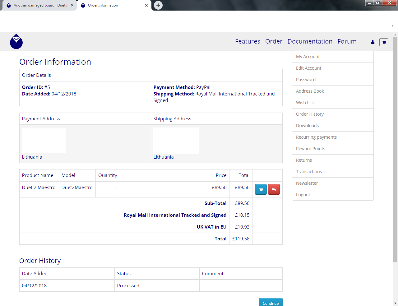
BTW what do you mean neither is original? The one on the left is def original. Clones have a brand on eth while original only serial. I purchased original from Duet3d:

-
RE: Another damaged boardposted in General Discussion
@bearer said in Another damaged board:
if the 3.3v regulator (U2) outputs 5v then odds are you need to replace the ethernet chip and processor as a minimum as well.
This is odd. I have checked U2 on the undamaged clone board and it outputs roughly the same voltage. It was weird for me too as it was 3.3V regulator but outputting almost 5V
-
RE: Another damaged boardposted in General Discussion
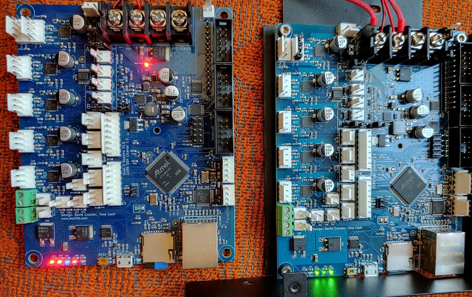
So i hooked up the board to check it further. I also ordered voltage regulators. Looks like it had more damage. Luckily i have a clone to compare(left one is original):

There is LED lit near 036N04L transistor and it shows zeroes.
Wander what else could be damaged.
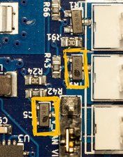
I have checked AP7361C-33E-13 and visually it has damage like on this writeup and photo:

but it outputs 4.9V
I have 24V output on one of the extruders and all LED's are lit except for 3.3V
Network shows no life, no LED's come up.
I am on 24V PSU.