Duet3D Logo Duet3D
    • Tags
    • Documentation
    • Order
    • Register
    • Login
    1. Home
    2. drmaestro
    3. Posts
    • Profile
    • Following 0
    • Followers 0
    • Topics 17
    • Posts 76
    • Best 1
    • Controversial 0
    • Groups 0

    Posts made by drmaestro

    • Hotend temperature overshoot - how much is acceptable?

      Hi,

      I've recently changed my system from 12 volts to 24 volts. As a result, I've changed my hotend heater. I had a 50 Watts 24 Volts heater, so I used it. Following PID tuning (I am on firmware 3.2), the initial temperature overshoot is 6 degrees when the temperature is set for 200 degrees. Afterwards, it stabilizes and changes between 199.9-200.1 degrees. Then I turn on part cooling fans and it overshoots by 1.4 degrees, then stabilizing at 199.7-199.9 degrees for 30-40 seconds and then stabilizes at 199.9-200.1 When I turn off the cooling fan, the temperature decreases to 198.4, then overshoots to 200.4 and is stabilized at 199.9-200.1

      Is the initial overshoot normal/expected? Is the behaviour of the heater in acceptable ranges?

      Thanks...

      posted in Tuning and tweaking
      drmaestroundefined
      drmaestro
    • RE: Have you ever observed this layer thickness problem?

      @dc42 @o_lampe @deckingman I've rebuilt the Y carriage, removed the twist that I used for smooth side of the belt on smooth idler, replaced the idler with a toothed one, retensioned. Here's a comparison of the object post-modifications:

      20210518_213826.jpg

      It turns out you were right, there should be something related to backlash on my setup. While I still have the artefacts, thery are not as prominent as they were previously. I may still have some ğrpblem on the X axis, which I'll also replace with another solution.

      posted in Tuning and tweaking
      drmaestroundefined
      drmaestro
    • RE: Have you ever observed this layer thickness problem?

      @argo That's very good. It means I have to go back to my printer and look for more mechanical issues....

      posted in Tuning and tweaking
      drmaestroundefined
      drmaestro
    • RE: Have you ever observed this layer thickness problem?

      @deckingman It used to flex a little bit when I was using groove mount on plastic version of my X car. So, I've bought an adapter (this one https://www.aliexpress.com/item/32890582038.html?spm=a2g0o.productlist.0.0.727965c11yqaj9&algo_pvid=a5da6614-4232-4c0e-ba6f-5602b69cf33f&algo_expid=a5da6614-4232-4c0e-ba6f-5602b69cf33f-14&btsid=0b0a555516211823561961742eb46d&ws_ab_test=searchweb0_0,searchweb201602_,searchweb201603_) , so it is metal on metal now. There was a very slight movement due to tolerances (or bad manufacturing), so I designed a plastic part that plugs to it and ifxes it in place.

      XCar.jpg

      There is no movement if you try to move the hotend (of course it is still bolted to plastic and the plastic can flex but I don't imagine it would flex during routine printer movements).

      posted in Tuning and tweaking
      drmaestroundefined
      drmaestro
    • RE: Have you ever observed this layer thickness problem?

      @deckingman Maybe. A problem with this object (with 0.8 mm thick wall) is that the slicer doesn't really consider it as an object with an internal and external perimeter. The fact that it is making a horseshoe turn makes the line a closed single loop, so a single line in fact, even though there should be two lines. I've loaded the 0.8 mm and 1 mm objects, and also another object with thicker walls to Prusa Slicer. Here's how they look at thelevel of a hole:

      Slicer.jpg

      The object on the bottom has external perimeters (orange) and internal perimeters (yellow). The object on top and right is the 0.8 mm object and it only has orange perimeters, so only external. The obejct on top left is the 1 mm object and while it has some gap fill between the perimeters, they still are external perimeters according to the color. Maybe that's the problem?

      So in this object's case, the object starts printing form the external line (even though internal perimeters first is selected) from a very close location to the hole, goes a few cm towards the hole, makes its 180 degree turn and goes to the internal line, finishes that line at the other end of the hole and makes its second turn to finish the external line (I have chosen aligned seems so it starts from very similar locations). Even if I chose to print with the external perimeters first option, it still performs the same trajectory (probably as a result of not having an internal perimeter) .

      posted in Tuning and tweaking
      drmaestroundefined
      drmaestro
    • RE: Have you ever observed this layer thickness problem?

      @dc42 I know that this is the first thing that comes to the mind when seeing this problem, however I am not sure about it. My reasons:

      • The object is being printed with the inner perimeters first, so it starts regularly, but then makes the horseshoe turn. This would imply the artefatct to be more visible on the exterior surfaces as the extrusion starts regularly .
      • I am using idlers which can be tensioned using bolts and I am using a voice frequency analyzer to tension the belts. They run very straight, with no wobble (I had wobble in the past, which I have corrected now).
      • The artefact is extremely regular
      • The wall thickness changes depending on the features on the object, so when there is a hole, the wall is thicker and I did cut with a cutter to see if there is a gap between the inner and outer walls, but there isn't any.
      • The artefact exists on both X and Y axis

      Could it be a side effect of interpolation ? (I don't know how it works, so that might be completely unrelated).

      Have you ever printed that object?

      posted in Tuning and tweaking
      drmaestroundefined
      drmaestro
    • RE: Have you ever observed this layer thickness problem?

      @o_lampe The pictures you've posted are from the outside of the object, where the effect is less visible. How does it look from the inside? In my case, the artifact is much more pronounced if you look at the inside walls. The lighting is also very important to be able to see the artifact (for example, in my third picture, it looks like there is no artifact at all at the inside wall, but if you shine the light with the appropiate angle (I used a flashlight) it is visible.

      I have tried with and without Arc Welder, there is no visible difference.

      Also, a funny coincidence, here's a post I've made 4 years ago, for the same problem in the RepRap forums, guess who did one of the answers belong to 😄
      https://reprap.org/forum/read.php?262,760790,760965#msg-760965

      posted in Tuning and tweaking
      drmaestroundefined
      drmaestro
    • RE: Have you ever observed this layer thickness problem?

      @o_lampe That should be interesting. The line width could also be a problem, as the slicer generally uses a slightly larger line width compared to the nozzle (0.45-0.46 instead of 0.4) but I don't think that's the problem, as the same line width will be used for the entire object and any error in wall thickness will be applied to everywhere, so there should be no visible changes.

      I changed the nozzle size in Prusa slicer to see how it draws the GCode. As the wall thickness is 0.8 mm, it just creates a single line and goes through the hole instead of looping, so in theory, the artifact shouldn't be visible (It has a similar behaviour for 1 mm thick version too).

      posted in Tuning and tweaking
      drmaestroundefined
      drmaestro
    • RE: Have you ever observed this layer thickness problem?

      @alankilian Thank you very much for sparing some time for printing the object. I am somehow relieved to see that it isn't specific to my printer only.

      @3DPMicro The GCode looks perfectly fine when loaded on a GCode viewer. The walls are straight. The STL itself has no visible problems when loaded in Solidworks. It looks as it is intended to look.

      @phaedrux The horseshoe shape can be a problem but that is the preferred method for all of the slicers I've tried. None of the slicers try to make that hole by retracting and going straight accross the hole. Maybe that is a fundamental error with the slicers themselves, who calculate the amount of plastic needed. The pressure advance might change how this looks but don't you think it is a huge amount of overextrusion for it to deal with? The pressure advance, especially on a direct drive extruder, isn't supposed to make that much of a change. While this part has been printed without pressure advance, I've used pressure advance in the past and I can still see the same artifacts.

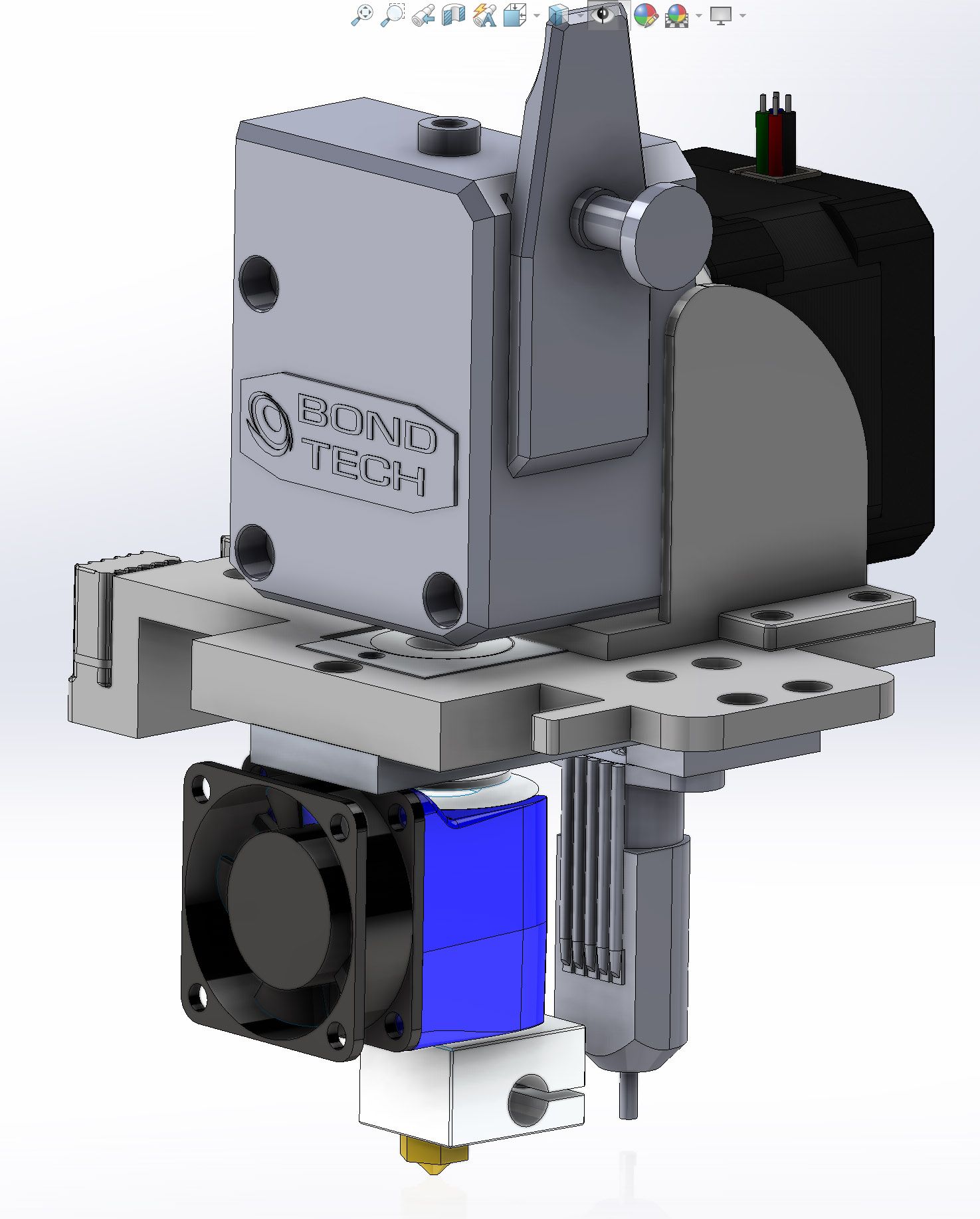
      Some more information about my configuration: It is a custom cartesian printer with Duet Wifi 1.04, running firmware 3.2. Bondtech BMG extruder.

      .
      Here's my config.g:

      ; Configuration file for Duet WiFi (firmware version 3)
      ; executed by the firmware on start-up
      ;
      ; generated by RepRapFirmware Configuration Tool v3.2.3 on Fri May 14 2021 14:28:05 GMT+0300 (GMT+03:00)
      
      ; General preferences
      G90                                            ; send absolute coordinates...
      M83                                            ; ...but relative extruder moves
      M550 P"Sigma 3D"                               ; set printer name
      
      ; Network
      M552 S1                                        ; enable network
      M586 P0 S1                                     ; enable HTTP
      M586 P1 S0                                     ; disable FTP
      M586 P2 S0                                     ; disable Telnet
      
      ; Drives
      M569 P0 S0                                     ; physical drive 0 goes backwards
      M569 P1 S0                                     ; physical drive 1 goes backwards
      M569 P2 S1                                     ; physical drive 2 goes forwards
      M569 P3 S0                                     ; physical drive 3 goes backwards
      M584 X0 Y1 Z2 E3                               ; set drive mapping
      M350 X16 Y16 Z16 E16 I1                        ; configure microstepping with interpolation
      M92 X80.00 Y80.00 Z400.00 E830.00              ; set steps per mm
      M566 X900.00 Y900.00 Z60.00 E1200.00           ; set maximum instantaneous speed changes (mm/min)
      M203 X7200.00 Y7200.00 Z180.00 E2400.00        ; set maximum speeds (mm/min)
      M201 X700.00 Y700.00 Z30.00 E700.00            ; set accelerations (mm/s^2)
      M906 X1400 Y1500 Z1400 E900 I30               ; set motor currents (mA) and motor idle factor in per cent
      M84 S30                                        ; Set idle timeout
      
      ; Axis Limits
      M208 X-20 Y0 Z0 S1                             ; set axis minima
      M208 X235 Y220 Z230 S0                         ; set axis maxima
      
      ; Endstops
      M574 X1 S1 P"!xstop"                           ; configure active-high endstop for low end on X via pin !xstop
      M574 Y1 S1 P"!ystop"                           ; configure active-high endstop for low end on Y via pin !ystop
      M574 Z0 P"nil" 					; Z has no endstop 
      ; Z-Probe
      M950 S0 C"exp.heater3"                         ; create servo pin 0 for BLTouch
      M558 P9 C"^zprobe.in" H5 F120 T4800            ; set Z probe type to bltouch and the dive height + speeds
      G31 P500 X29 Y0 Z0.75                          ; set Z probe trigger value, offset and trigger height
      M557 X30:190 Y5:195 S20                        ; define mesh grid
      
      ; Heaters
      M308 S0 P"bedtemp" Y"thermistor" T100000 B4138 ; configure sensor 0 as thermistor on pin bedtemp
      M950 H0 C"bedheat" T0                          ; create bed heater output on bedheat and map it to sensor 0
      M307 H0 B0 S1.00                               ; disable bang-bang mode for the bed heater and set PWM limit
      M140 H0                                        ; map heated bed to heater 0
      M143 H0 S120                                   ; set temperature limit for heater 0 to 120C
      M308 S1 P"e0temp" Y"thermistor" T100000 B4725 C7.06e-8  ; configure sensor 1 as thermistor on pin e0temp
      M950 H1 C"e0heat" T1                           ; create nozzle heater output on e0heat and map it to sensor 1
      M307 H1 R2.322 C219.7 D9.80 S1.00 V24.0        ; disable bang-bang mode for heater  and set PWM limit
      M143 H1 S300                                   ; set temperature limit for heater 1 to 300C
      
      ; Fans
      M950 F0 C"fan0" Q500                           ; create fan 0 on pin fan0 and set its frequency
      M106 P0 S0 H-1                                 ; set fan 0 value. Thermostatic control is turned off
      M950 F1 C"fan1" Q500                           ; create fan 1 on pin fan1 and set its frequency
      M106 P1 S1 H1 T45                              ; set fan 1 value. Thermostatic control is turned on
      M950 F2 C"fan2" Q500                           ; create fan 2 on pin fan2 and set its frequency
      M106 P2 S1 H-1                                 ; set fan 2 value. Thermostatic control is turned off
      
      ; Tools
      M563 P0 D0 H1 F0:2                             ; define tool 0
      G10 P0 X0 Y0 Z0                                ; set tool 0 axis offsets
      G10 P0 R0 S0                                   ; set initial tool 0 active and standby temperatures to 0C
      
      ; Custom settings are not defined
      
      ; Miscellaneous
      M575 P1 S1 B57600                              ; enable support for PanelDue
      T0                                             ; select first tool


      Here are some settings for the print that I've copied from the GCode:

      ; generated by PrusaSlicer 2.3.1+win64 on 2021-05-15 at 16:38:11 UTC
      
      ; 
      
      ; external perimeters extrusion width = 0.45mm
      ; perimeters extrusion width = 0.45mm
      ; infill extrusion width = 0.45mm
      ; solid infill extrusion width = 0.45mm
      ; top infill extrusion width = 0.40mm
      
      M107
      G10 S210 ; set temperature
      ;TYPE:Custom
      M561;Clear bed transforms
      G28 XY; Home X and Y axis
      M280 P3 S10 I1; BLTouch Pin down
      G1 X100 Y100; Go to 100
      G28 Z;
      G29 S1 ; Bed leveling with already recorded height map
      M280 P3 S90 I1; BLTouch pin up
      G10 S210 ; set temperature
      M116 ; wait for temperature to be reached
      G21 ; set units to millimeters
      G90 ; use absolute coordinates
      M83 ; use relative distances for extrusion
      ; Filament gcode
      ; filament used [mm] = 2126.85
      ; filament used [cm3] = 5.12
      ; total filament used [g] = 0.00
      ; total filament cost = 0.00
      ; estimated printing time (normal mode) = 57m 56s
      
      ; avoid_crossing_perimeters = 0
      ; avoid_crossing_perimeters_max_detour = 0
      ; bed_custom_model = 
      ; bed_custom_texture = 
      ; bed_shape = 0x0,200x0,200x220,0x220
      ; bed_temperature = 0
      ; before_layer_gcode = 
      ; between_objects_gcode = 
      ; bottom_fill_pattern = monotonic
      ; bottom_solid_layers = 2
      ; bottom_solid_min_thickness = 0
      ; bridge_acceleration = 0
      ; bridge_angle = 0
      ; bridge_fan_speed = 100
      ; bridge_flow_ratio = 1
      ; bridge_speed = 60
      ; brim_width = 0
      ; clip_multipart_objects = 1
      ; color_change_gcode = M600
      ; complete_objects = 0
      ; cooling = 0
      ; cooling_tube_length = 5
      ; cooling_tube_retraction = 91.5
      ; default_acceleration = 0
      ; default_filament_profile = 
      ; default_print_profile = 
      ; deretract_speed = 0
      ; disable_fan_first_layers = 3
      ; dont_support_bridges = 1
      ; draft_shield = 0
      ; duplicate_distance = 6
      ; elefant_foot_compensation = 0.2
      ; end_filament_gcode = "; Filament-specific end gcode \n;END gcode for filament\n"
      ; end_gcode = M104 S0 ; turn off temperature\nM140 S0 ; turn off bed\nG28 X0  ; home X axis\nM84     ; disable motors\n
      ; ensure_vertical_shell_thickness = 0
      ; external_perimeter_extrusion_width = 0
      ; external_perimeter_speed = 50%
      ; external_perimeters_first = 0
      ; extra_loading_move = -2
      ; extra_perimeters = 1
      ; extruder_clearance_height = 20
      ; extruder_clearance_radius = 20
      ; extruder_colour = ""
      ; extruder_offset = 0x0
      ; extrusion_axis = E
      ; extrusion_multiplier = 1
      ; extrusion_width = 0
      ; fan_always_on = 1
      ; fan_below_layer_time = 60
      ; filament_colour = #29B2B2
      ; filament_cooling_final_speed = 3.4
      ; filament_cooling_initial_speed = 2.2
      ; filament_cooling_moves = 4
      ; filament_cost = 0
      ; filament_density = 0
      ; filament_diameter = 1.75
      ; filament_load_time = 0
      ; filament_loading_speed = 28
      ; filament_loading_speed_start = 3
      ; filament_max_volumetric_speed = 0
      ; filament_minimal_purge_on_wipe_tower = 15
      ; filament_notes = ""
      ; filament_ramming_parameters = "120 100 6.6 6.8 7.2 7.6 7.9 8.2 8.7 9.4 9.9 10.0| 0.05 6.6 0.45 6.8 0.95 7.8 1.45 8.3 1.95 9.7 2.45 10 2.95 7.6 3.45 7.6 3.95 7.6 4.45 7.6 4.95 7.6"
      ; filament_settings_id = "PLA No Heated Bed"
      ; filament_soluble = 0
      ; filament_spool_weight = 0
      ; filament_toolchange_delay = 0
      ; filament_type = PLA
      ; filament_unload_time = 0
      ; filament_unloading_speed = 90
      ; filament_unloading_speed_start = 100
      ; filament_vendor = (Unknown)
      ; fill_angle = 45
      ; fill_density = 20%
      ; fill_pattern = grid
      ; first_layer_acceleration = 0
      ; first_layer_bed_temperature = 0
      ; first_layer_extrusion_width = 0
      ; first_layer_height = 0.2
      ; first_layer_speed = 30
      ; first_layer_temperature = 210
      ; full_fan_speed_layer = 0
      ; gap_fill_speed = 20
      ; gcode_comments = 0
      ; gcode_flavor = reprapfirmware
      ; gcode_label_objects = 0
      ; high_current_on_filament_swap = 0
      ; host_type = octoprint
      ; infill_acceleration = 0
      ; infill_anchor = 600%
      ; infill_anchor_max = 50
      ; infill_every_layers = 1
      ; infill_extruder = 1
      ; infill_extrusion_width = 0
      ; infill_first = 0
      ; infill_only_where_needed = 0
      ; infill_overlap = 25%
      ; infill_speed = 60
      ; interface_shells = 0
      ; ironing = 0
      ; ironing_flowrate = 15%
      ; ironing_spacing = 0.1
      ; ironing_speed = 15
      ; ironing_type = top
      ; layer_gcode = 
      ; layer_height = 0.2
      ; machine_limits_usage = emit_to_gcode
      ; machine_max_acceleration_e = 10000,5000
      ; machine_max_acceleration_extruding = 1500,1250
      ; machine_max_acceleration_retracting = 1500,1250
      ; machine_max_acceleration_x = 9000,1000
      ; machine_max_acceleration_y = 9000,1000
      ; machine_max_acceleration_z = 500,200
      ; machine_max_feedrate_e = 120,120
      ; machine_max_feedrate_x = 500,200
      ; machine_max_feedrate_y = 500,200
      ; machine_max_feedrate_z = 12,12
      ; machine_max_jerk_e = 2.5,2.5
      ; machine_max_jerk_x = 10,10
      ; machine_max_jerk_y = 10,10
      ; machine_max_jerk_z = 0.2,0.4
      ; machine_min_extruding_rate = 0,0
      ; machine_min_travel_rate = 0,0
      ; max_fan_speed = 100
      ; max_layer_height = 0
      ; max_print_height = 200
      ; max_print_speed = 80
      ; max_volumetric_speed = 0
      ; min_fan_speed = 100
      ; min_layer_height = 0.08
      ; min_print_speed = 10
      ; min_skirt_length = 0
      ; notes = 
      ; nozzle_diameter = 0.4
      ; only_retract_when_crossing_perimeters = 0
      ; ooze_prevention = 0
      ; output_filename_format = [input_filename_base].gcode
      ; overhangs = 1
      ; parking_pos_retraction = 92
      ; pause_print_gcode = M601
      ; perimeter_acceleration = 0
      ; perimeter_extruder = 1
      ; perimeter_extrusion_width = 0
      ; perimeter_speed = 50
      ; perimeters = 3
      ; physical_printer_settings_id = 
      ; post_process = 
      ; print_settings_id = Sigma 3D
      ; printer_model = 
      ; printer_notes = 
      ; printer_settings_id = Sigma 3D
      ; printer_technology = FFF
      ; printer_variant = 
      ; printer_vendor = 
      ; raft_layers = 0
      ; remaining_times = 0
      ; resolution = 0
      ; retract_before_travel = 0.5
      ; retract_before_wipe = 0%
      ; retract_layer_change = 0
      ; retract_length = 0.8
      ; retract_length_toolchange = 10
      ; retract_lift = 0
      ; retract_lift_above = 0
      ; retract_lift_below = 0
      ; retract_restart_extra = 0
      ; retract_restart_extra_toolchange = 0
      ; retract_speed = 40
      ; seam_position = aligned
      ; silent_mode = 1
      ; single_extruder_multi_material = 0
      ; single_extruder_multi_material_priming = 1
      ; skirt_distance = 4
      ; skirt_height = 1
      ; skirts = 4
      ; slice_closing_radius = 0.049
      ; slowdown_below_layer_time = 5
      ; small_perimeter_speed = 20
      ; solid_infill_below_area = 5
      ; solid_infill_every_layers = 0
      ; solid_infill_extruder = 1
      ; solid_infill_extrusion_width = 0
      ; solid_infill_speed = 20
      ; spiral_vase = 0
      ; standby_temperature_delta = -5
      ; start_filament_gcode = "; Filament gcode\n"
      ; start_gcode = M561;Clear bed transforms\nG28 XY; Home X and Y axis\nM280 P3 S10 I1; BLTouch Pin down\nG1 X100 Y100; Go to 100\nG28 Z;\nG29 S1 ; Bed leveling with already recorded height map\nM280 P3 S90 I1; BLTouch pin up\n
      ; support_material = 0
      ; support_material_angle = 45
      ; support_material_auto = 0
      ; support_material_buildplate_only = 0
      ; support_material_contact_distance = 0.2
      ; support_material_enforce_layers = 0
      ; support_material_extruder = 1
      ; support_material_extrusion_width = 0
      ; support_material_interface_contact_loops = 0
      ; support_material_interface_extruder = 1
      ; support_material_interface_layers = 1
      ; support_material_interface_spacing = 0
      ; support_material_interface_speed = 100%
      ; support_material_pattern = rectilinear
      ; support_material_spacing = 3
      ; support_material_speed = 60
      ; support_material_synchronize_layers = 0
      ; support_material_threshold = 45
      ; support_material_with_sheath = 0
      ; support_material_xy_spacing = 50%
      ; temperature = 200
      ; template_custom_gcode = 
      ; thin_walls = 1
      ; threads = 8
      ; thumbnails = 
      ; toolchange_gcode = 
      ; top_fill_pattern = monotonic
      ; top_infill_extrusion_width = 0
      ; top_solid_infill_speed = 30
      ; top_solid_layers = 3
      ; top_solid_min_thickness = 0
      ; travel_speed = 90
      ; use_firmware_retraction = 0
      ; use_relative_e_distances = 1
      ; use_volumetric_e = 0
      ; variable_layer_height = 1
      ; wipe = 0
      ; wipe_into_infill = 0
      ; wipe_into_objects = 0
      ; wipe_tower = 0
      ; wipe_tower_bridging = 10
      ; wipe_tower_no_sparse_layers = 0
      ; wipe_tower_rotation_angle = 0
      ; wipe_tower_width = 60
      ; wipe_tower_x = 180
      ; wipe_tower_y = 140
      ; wiping_volumes_extruders = 70,70
      ; wiping_volumes_matrix = 0
      ; xy_size_compensation = 0
      ; z_offset = 0


      I was wondering, if more people are willing to print this object and post a picture.

      posted in Tuning and tweaking
      drmaestroundefined
      drmaestro
    • Have you ever observed this layer thickness problem?

      Hi,

      This problem has been a huge challenge for me and I was wondering if anybody else had this problem.

      I have observed that objects with certain features, like holes, modified the layer thickness at that layer. This effect is not very visible with organic shapes, like statues or figurines, but quite obvious for objects with straight walls. One object where this problem is very obvious is the XY-test object file from Make 2016/2017 3D Printer Test (https://www.thingiverse.com/thing:2071696/files) . Here's a picture demonstrating the problem (I've printed it at 120% scale, it made the problem more visible):

      ![XYTest.jpg

      The leftmost picture is where the problem is most obvious. There is a very regular band whenever there is a hole (there is a second hole on the object but it isn't visible on the picture, however its artefact is). The opposite wall (second picture) has the same problem but it is inverted (it is as if there was a layer shift). However, when I look at the external walls (third and forth pictures), there is no layer shift at all (at least it isn't visible as prominently).

      Now whenever I asked this question on other forums I got some suggestions about the belts not being tight enough or being too tight. I don't believe that's the problem, as the artefact is too regular and not equally visible on both sides. I don't think this is a temperature problem (there is no fluctuations on the hotend and the bed was turned off). The artifeact is visible on Prusa Slicer, Cura, and Simplify 3D (the pictures are forum Prusa Slicer version), so I don't think this is related to the slicers too (they all print the object the same way: Regular one sided movements on parts without the walls, and 180 degree returns at the holes. Interestingly no slicer tries to print the layers with the hole by moving stragiht, going past the hole by retracting and continuing from the other side of the hole. I wonder if the results would be different if they printer like this). The object itself looks very straight without artifacts when loaded to the slicers, so I don't think this is a problem with the object's design (one problem could be that there are 2 versions of this object, one with 0.8 mm thick walls and one with 1 mm thick walls, however the problem is visible on both of them, but slightly less prominent on 1 mm object). My extruder is calibrated (it is a standard BMG and I've performed the extruder calibration a few times).

      I am out of ideas. Maybe this is a problem with all of the slicers, making some approximations, which become visible at certain parts. Maybe it is specific to Duet (I'd highly doubt it). Maybe it is a problem with how slicers calculate extrusion amount and it changes at each layer (so each layer's thickness is slightly different). Maybe it is a limitation of the FDM process itself.

      Do you have any theoies/ideas? Have you ever tried to print this object?

      posted in Tuning and tweaking
      drmaestroundefined
      drmaestro
    • RE: From 2.04 to 3... Pros and cons?

      @phaedrux Thank you. I've followed a similar reply you'd given in another post and upgraded to 3.2 It was a very easy process, and didn't cause any complications (except the Wifi not connecting when I upgraded to 3.2 form 3, but a reset did fix the problem).

      To be fair, the firmware wiki makes the upgrade process sound harder than it really is. IMHO using RepRap configurator is definitely the way to go when upgrading form 2. to 3. as it creates a very clean configuration file. Having the old config.g is very handy, as most of the info required by the configurator is already there.

      The only problems I've encountered were the reversal of direction on the X and Y axis, easily corrected by changing them in the firmware (have no idea why. Probably something changed with the way firmware 3 handles the directions on these axis) . Also, the homeall.g and homez.g files didn't include the G30 command required for my BLTouch (I am almost sure that I choose it in the configurator but maybe I missed it, maybe there is an error with the configurator), which could be a real problem creating a crash if I didn't check the files before using the commands.

      I also checked the change logs. Most of the information there is quite technical in nature and mostly geared towards newer cards (Duet 3). And you are also right, I haven't seen any mention about print quality improvement, so no real need to upgrade just for the quality (which could change of course with input shaping).

      Thanks again for all the information you've provided....

      posted in Firmware installation
      drmaestroundefined
      drmaestro
    • From 2.04 to 3... Pros and cons?

      Hi,

      I have a Duet 2 Wifi and I am on the latest 2. firmware (2.05.1). I am trying to decide if I need to upgrade to 3. firmware.

      My main concern is print quality, not speed, so any progress in that front is a justification for me to make the update. I've read that input shaping is being planned for the 3. series, so this is a factor could be important. Are there any other advantages to upgrade to version 3 print quality wise?

      Also, are there any disadvantages on upgrading? I've read some problems with loss of performance (decreased available steps) but I think this issue is getting better and not that important if you aren't running on very high speeds or very high microsteps.

      Is the best way to upgrade is by using the reprap configurator, as it seems there are important changes on the config files and maybe starting from zero is a better solution.

      Thanks...

      posted in Firmware installation
      drmaestroundefined
      drmaestro
    • RE: 24 Volts Bed Heater Problem

      @joel The 2 12 V fans don't run at the same time. One is for cooling the Duet board (always on), one is a part cooling blower (PWM fan), so probably cannot be run in series.

      posted in Duet Hardware and wiring
      drmaestroundefined
      drmaestro
    • RE: 24 Volts Bed Heater Problem

      @dc42 Thanks. I did the re-wiring and made a change to the config.g (the F2 fan was set to be controlled thermostatically, I removed it). All of the fans work as they should now. Thanks again everybody.

      I'll now have to wait pateintly for the new bed heater. I hope my 350 w power supply will be enough. I am trying to make the calculations using the Wiki page:

      • The bed will be 200 Watts

      • The hotend is 50 Watts (I also have 40 Watts if I need to decrease the power usage)

      • I have 5 steppers. 2 Of them are Pololu steppers with threaded rods. They are 2.8 Volts, 1.7 A, so 4.8 Watts per motor. The extruder is 2.5 Volts, 1.2 A (3 Watts). The Y axis motor is 3.4 Volts, 1.7 A (5.8 Watts), The X axis is 2.8 Volts, 1.7 A (4.8 Watts). In total the steppers require 23-24 Watts. The wiki advises to add 50% to that number, so that's 36 Watts.

      • I have 2 blower fans (one 24 V, one 12V (soon to be replaced),, 1 hot end fan and one 8 cm fan for cooling Duet. The 8 cm fan is 12 Volts, 0.18 A (2.2 Watts), The 12 v blower is 0.09A (1.08 Watts), the 24 V blower is 0.06 A (1.44 Watts) and the 24 V Hotend fan is 0.08 A (1.92 Watts). In total, the fans require 6.65 Watts.

      • I have a 7 Inch Panel Due (3.5 Watts according to Wiki)

      • Duet itself 2 Watts according to Wiki.

      • BLTouch, not entirely sure but the web site talks about 5 Volts and a current of 15 mA to 300 mA (peak), so assuming the peak current, it should be around 1.5 Watts

      That's my current configuration and in toal it is 299.65 Watts. I assume the 350 Watts power supply is adequate for this purpose.

      Also, I plan on changing the part cooling fans with an air pump (the berd-air pump) in the future. The web site mentions the 24 Volts pump's rated current is 1200 mA, but then in the next line it mentions Current rating: 150 ma @ 24 v, so I can't really calculate the power requirement: ıs it 24x1.2A =28.8 Watts or 24x0.15=3.6 Watts? If it is the first, the 350 Watts power supply may be at it limits, if it is the second, then it isn't a problem. (the web site is https://the-makerhive.myshopify.com/products/berd-air-max?variant=33133668499591)

      Edit: On AliExpress, there is a similar pump which talks about 12 Watts, so maybe that's the correct number and there may be a possibility to run it with the 350 Watts PSU

      posted in Duet Hardware and wiring
      drmaestroundefined
      drmaestro
    • RE: 24 Volts Bed Heater Problem

      The bed heater works but immediately resets the duet, as the power supply cannot keep up with the 500 Watts request (it is a 350 Watts PSU). I ordered a 200 Watts bed heater now. I assume the circuit itself is ok, as if it was burn't I wouldn't be seeing any increase in the temperature.

      As a side note, I removed the fan connectors, removed the crimps, connected them directly to the PSU to individually test them and they work, so it is probably some bad wiring by me creating the 24 volts fans not working problem.

      I read the fan page on the wiki. As I understand, it is possible to either use all 5 volts fans (I don't have any), use all 24 volts fans (in that case I need 1 more 24 volts blower and a 24 volts large fan to cool the Duet board), use all 12 volts fans (in that case I'll need a buck converter, that I already have, and connect the +and - inputs of the converter to my 24 Volts PSU, and connect the positive output to V-fan jumper. I that case, all of the fans (PWM and always on) will be 12 volts. Or in my case, if I want to use 2 24 volts and 2 12 volts fans, I need to apply 24 volts to V-fan jumper (which means I can leave the jumper in place, as my PSU is 24 volts and V in will provide that 24 volts), however for the 12 volt fans I need to apply 12 volts from a buck converter, but the negative ends will go to the Fan - connectors. I assume I can use a single buck converter for supplying 2 12 Volts fans (the buck coverter can output 3 A, so it should be enough). My best option, until I have a all 24 Volts setup, seems to use the last option, which will require a minimal chang in wiring only.

      Anything wrong with my understanding?

      posted in Duet Hardware and wiring
      drmaestroundefined
      drmaestro
    • RE: 24 Volts Bed Heater Problem

      @joel Yes, normally it starts at around 45-50 degrees but I tried to heat it to 80 degrees and it didn't start.

      Cooling fan = part cooler

      I am using almost the same config, except I added the second 12 volts fan as a cooling fan to tool one (orisignally both of my fans where connected to a single fan output, now that one of them is 12 volts, I had to use a second fan output).

      Either way, none of the fans (part cooling and hotend) are working, even if they are on always on connector, so there definitely is a problem on the fans or the wiring....

      @jens55 I am aware of the polarity issue and was careful to wire the right polarity.

      posted in Duet Hardware and wiring
      drmaestroundefined
      drmaestro
    • RE: 24 Volts Bed Heater Problem

      @joel I have tried to run the hotend fan and also the cooling fan (the 24 volts one) using the always on fan connectors and they aren't working. Maybe there is a problem with the fans themselves or the wiring (I use a 12 volts always on fan for cooling the Duet board and it is working without a problem on the always on connectors).

      posted in Duet Hardware and wiring
      drmaestroundefined
      drmaestro
    • RE: 24 Volts Bed Heater Problem

      @jens55 I have a 220x220 bed.

      posted in Duet Hardware and wiring
      drmaestroundefined
      drmaestro
    • RE: 24 Volts Bed Heater Problem

      @joel I haven't been able to find one, I'll search for it.

      posted in Duet Hardware and wiring
      drmaestroundefined
      drmaestro
    • RE: 24 Volts Bed Heater Problem

      @joel I have a 50 watts hot-end heater

      posted in Duet Hardware and wiring
      drmaestroundefined
      drmaestro