@stuartofmt one for @chrishamm
Ian
@maximyz3d there’s a GitHub issue for this here: https://github.com/Duet3D/RepRapFirmware/issues/780
It hasn’t been implemented yet.
Ian
For our application we are on the same gcode line for extended period of time (Long and slow runs)
You will want to enable segmentation of long moves, which splits them up into shorter moves, and means the move is interruptible. See the general CNC guide for configuration that may be applicable to your setup: https://docs.duet3d.com/en/User_manual/Machine_configuration/Configuration_CNC
There is a limit on the number of steps a move can be, which may be relevant. I think it is 2^32 steps (@dc42 ?). It’s possible to hit this on a long or rotating axis that has a high number of steps per mm.
Ian
@Leonard03 It's possibly your issue is similar to the one reported in this thread: https://forum.duet3d.com/topic/37545/mini-5-wifi-problem-revisited/. We have asked @rechrtb to look into it.
Ian
@fcwilt we’ve asked @rechrtb to look into this issue. If he comes up with anything, it would be good if you could test it?
Ian
@Leonard03 Is the PanelDue firmware up to date? It should be on 3.5.1: https://github.com/Duet3D/PanelDueFirmware/releases/latest
Ian
@thomasvanderwal said in Duet 2 v1.02 not responding:
How can I clean a nozzle? I think its full or something. The tube (hot end?) before the nozzle is that also to clean?
Usually, if you heat up the nozzle to 200C, you can push out old filament with new filament. If it was printing a different material, eg ABS or Nylon, you may need higher temperatures, eg 230-240. Don't leave it at this temperature when the PLA goes through.
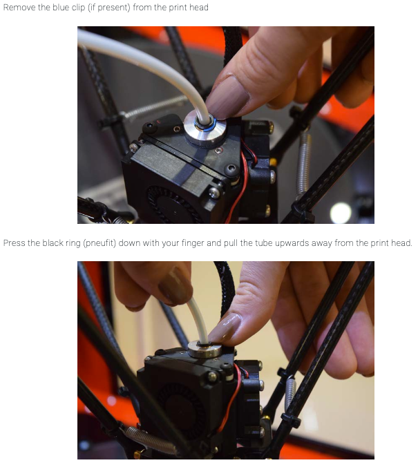
The feed tube may also have filament in it, it just means you have to push more filament through. Or you can detach the feed tube from the top of the nozzle, and pull the filament back out by hand. To take off the tube, shows this in the pdf manual.
If you can't push filament through at all, you may need to diassemble the hot end. Unfortunately the manual doesn't seem to cover this.
Ian
@thomasvanderwal said in Duet 2 v1.02 not responding:
My latest concern is the leveling
What's the problem? Most likely you need to do the bed calibration, for which you need the probe to work. Is the probe working now?
Also check that the motors move the effector the correct distance. See the "Check distance moved" section of https://docs.duet3d.com/en/How_to_guides/Commissioning#h-10-check-stepper-motors
For a delta printer, it's easiest to check movement in the Z axis, eg measure from bed to nozzle, move it down 50mm in DWC, then measure from bed to nozzle and check it moved 50mm.
Ian
@thomasvanderwal said in Duet 2 v1.02 not responding:
extrude en retract seems to go the wrong way.
Change the M569 S parameter for the extruder. See "Reversing a stepper motor" in https://docs.duet3d.com/en/How_to_guides/Commissioning#h-10-check-stepper-motors
Also my PLA goos neary through the opening
I'm not sure what you mean.
But I don't know if the extrusion or retracting button on my duetPanel works also with this code.
Can you show a picture of what buttons you mean?
Ian
@konvalm What PC are you trying to flash the 6HC with? MacOS doesn't work, unfortunately. Windows and Linux should work fine. Make sure you follow the guide here: https://docs.duet3d.com/User_manual/RepRapFirmware/Updating_firmware#fallback-procedure-2
Main tips for successful flashing:
Ian
@thomasvanderwal You don't need to use the filament functionality of DWC/RRF. I don't! I just put the filament in that I'm going to use, and set up the slicer with the correct filament. It's up to you.
Creating a new filament should create the /filaments folder if there isn't one already. See https://docs.duet3d.com/en/User_manual/Reference/DWC_filaments
Ian
@Chriss @dc42 tested M116 last night, and found it to be working correctly from his tests. These were very simplified, please could you try the same?
Test 1 (tested with 3.6.0-beta.4 in standalone mode):
T1
G1 X-50 Y-50
Test 2
Notes fro dc42
And perhaps most importantly ... !
Ian
@maximyz3d You may be able to do some simple UI stuff with the DWC plug in BtnCmd https://github.com/MintyTrebor/BtnCmd
Note that for a DRO the machine position is not "live", it is updated in the Object Model every 250ms. If you're connecting over a network, there is also the latency of the network.
Ian
@gwatson90 Most electronics are rated at 80°C, and typically have some level of self-heating, and running at that temperature drastically reduces their life time. So electronics in chambers that reach more than 60°C should be avoided. This includes toolboard, probes (like the BLTouch) and even some connectors. Use wires and connectors that are rated for the expected temperature.
Ian
@genioluiz7 I've read back through the forum thread, and it does seem that the WiFi module has failed. Because the firmware on the Duet was also erased, I'd suspect either a wiring short or ESD "static electricity" shock has caused it to fail. The way that the Duet circuit is designed is that short circuits to the 3.3V rail are first absorbed by the SD card holder and WiFi module, hopefully before the main processor, so that they fail first. They are easier to replace than the main processor.
Most likely you will need to replace the WiFi module. If you can't do this yourself, there may be others local to you that can help, see https://forum.duet3d.com/topic/13875/community-repairs. Unfortunately Duet3D does not carry out these repairs itself. Otherwise, I think you will need to replace the Duet board.
Ian
@dwuk said in Sovol SV08 Multiple Motion System Upgrade.:
I noticed that in the documentation it mentions something about macro's only using one stream.
Do you mean this setion? https://docs.duet3d.com/en/User_manual/RepRapFirmware/Multiple_motion_systems#macros-and-motion-systems
I'm not sure if this is changed behaviour between 3.5 and 3.6, or at least how it deals with multiple motion within macros may have changed, as you say it was working in 3.5. I'll check with @dc42.
Ian
@thomasvanderwal Any slicer is fine, the devil is in the detail of setting up the slicer correctly. I use the open source Prusaslicer, Orcaslicer and occasionally Cura. I don't use Simplify3D as it is paid-for software, and the open source options are just as good. Try and find a good guide to setting up the slicer profile for your machine.
You may also want to calibrate your steps per mm (ie make sure that when you command a 10mm movement it actually moves 10mm), and at your speeds and accelerations, which are set to the default at the moment.
We have a basic Calibration guide here: https://docs.duet3d.com/en/How_to_guides/Calibration . While our guide is good for basic calibration, you may want to fine tune everything. Teaching Tech has a good set of guides here: https://teachingtechyt.github.io/calibration.html
Ian
@westech I'm a bit confused about what you're asking.
Is it that you can't set up a printer? You can either use the "Setup Wizard" and choose "Generic RRF printer", or "Create printer" from the printer drop-down box. When setting up a new printer in Orca, I don't select a printer profile, I create a new one with the "Can't find my printer model" tickbox selected (I find this way more awkward, though, more options!).
Do you mean you can't find where to edit the start and end gcode in Cura? Click on the icon next to the printer name (in the printer drop-down box), and it will show the Printer settings. Go to the "Machine G-code" tab.
Ian
@thomasvanderwal said in Duet 2 v1.02 not responding:
but first Ihave to sesolve (or you haha) this
I said this earlier: You need to tune both the bed and extruder heaters. See https://docs.duet3d.com/en/How_to_guides/Commissioning#h-7-tune-heaters
Ian
@mendelevium Duet boards and RepRapFirmware support CNC machines. There is a CNC section of the forum (which I've moved this thread to) and a page for setting up CNC machines on the wiki, see https://docs.duet3d.com/User_manual/Machine_configuration/Configuration_CNC
Ian
