Thank you all for your answers and your tips, even though I couldn't find a solution after hours of tinkering. That's why I admitted defeat and ordered new, better suited stepper motors. The old ones were 0.9° motors with sub-optimal parameters (according to the EMF calculator) which gave me a lot of reliability issues, mainly random unpredictable step losses. For this reason I wanted to upgrade to the JMC servos that I had lying around anyway, just to open another can of worms 
Live and learn I guess... Thanky anyway! ")
Posts made by Eumldeuml
-
RE: Gradual layer shifts with integrated JMC stepper servosposted in Tuning and tweaking
-
RE: Gradual layer shifts with integrated JMC stepper servosposted in Tuning and tweaking
@droftarts Yes, the steps/mm are quite low. I did that temporarily to highlight the issue and to find a clue faster.
Mechanical issues are most certainly not the root cause, as I checked everything when installing the motors. Good hint though that it might be just one of the motors that has an issue as this will influence movements in both X and Y. Still not sure on how to diagnose this any further. While changing from steppers to the servos I did try to make a few moves with one servo and one stepper but that threw the stepper off almost instantly.The R-1 is for silencing these annoying popups about one stepper motor not being connected properly (out of phase or something). I mean, there isn't even a stepper connected. Those popups are appearing anyway, with or without R-1.
-
RE: Gradual layer shifts with integrated JMC stepper servosposted in Tuning and tweaking
I did manage to try the 5V signalling but it also didn't make any difference. That was the last lead and I don't really know what I could try next, which is very frustrating. Other people are using JMCs as well so it should work...
There might be something wrong with the motors internally but I don't have the money to just buy new ones without really knowing if they are indeed the problem...@dc42 Can you think of anything else to try? If not I still want to thank you for your input and your support in this forum
-
RE: Gradual layer shifts with integrated JMC stepper servosposted in Tuning and tweaking
@dc42 Changing SW5 didn't make a difference sadly.
I did find out though that the motors do sound very crunchy in some manual jogging moves when setting M569 T3:3:6:0. They also lose steps or rather they don't get transmitted correctly as the servo's encoders are hopefully doing their job. The toolhead crashed when trying to pick up a tool right after homing.
The documentation on connecting external stepper motors states that for long cables or cables with high capacitance one should increase the timing values, that's why I tried on going higher with those values. There might be something to that, as witnessed by the motors losing their intended position when using short timings.That leaves the barely high enough 3.6V signalling voltage as the next possible candidate. As per documentation of the EBB:
"Connecting STEP+ from your driver to +5V, which is available on the H6_PWM and/or H7_PWM pin headers (see wiring diagram above), and STEP- for your driver to STEP- on the expansion board"
If I understand correctly, this means there won't be any direct connection from STEP+ on the driver/motor to STEP+ on the EBB? But the signals will still be differential? That doesn't seem to be clear to me. -
Gradual layer shifts with integrated JMC stepper servosposted in Tuning and tweaking
Hi all!
(config and hardware at the end)
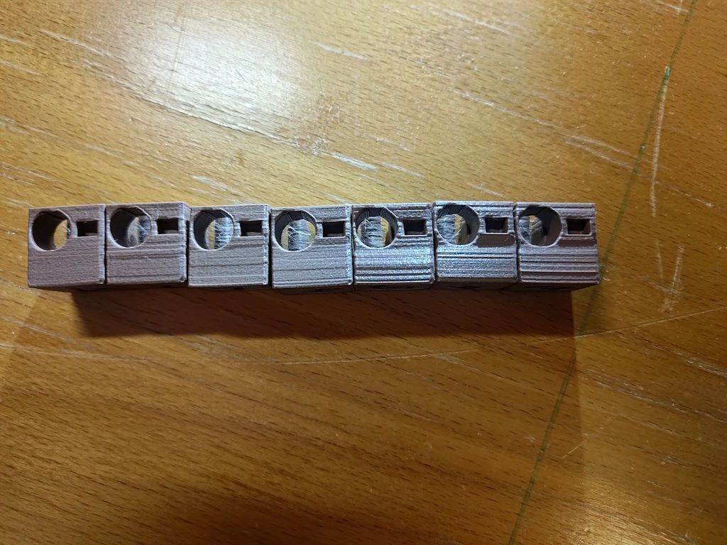
My CoreXY DIY toolchanger is running great with the exception of the integrated JMC stepper servos on X and Y that I tried to get working (again). The problem of gradual layer shifts is shown in the pictures. All the cubes are printed one after the other, same gcode, just different motor parameters (M569 mostly).
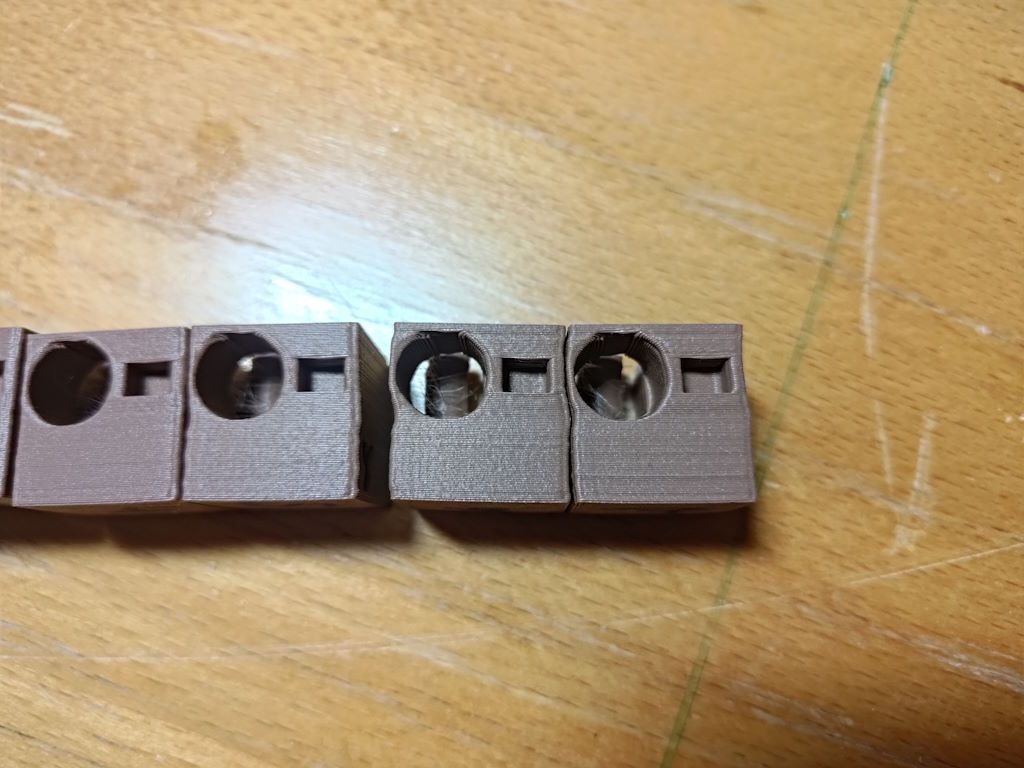
A few observations: The leftmost cube was printed with my normal microstepping rate (160 steps/mm), the other ones use the coarsest setting on the motors (20 steps/mm) to highlight the issue. On the second picture you can see that the error is reproducible which rules out random interference. Just increasing the microsteps gets rid of the issue (or rather it doesn't show as much), but the prints are still a lot worse than with stepper motors.
The parameters changes from left to right are:- base line (see attached config.g)
- Microsteps to 20 steps/mm
- Connected shield of step/dir differential signal cable to GND
- Changed M569 T4:8:12:12 to T4:16:12:12
- -> T4:32:32:32
- -> T4:32:8:0
- -> T8:8:8:0
My wild guess is that there might be something wrong with the setting of the direction pin in regards to the step pulses. I tried checking that with the oscilloscope (seperately, not during printing) and it looked like there is ages between a change on the direction pin and the first step pulse. Can't remember the exact number but it was more in the range of milliseconds, not microseconds which is way more than enough. The timing parameters I tried are all well above the minimum stated by the datasheet. I haven't found a way to check the signals during printing, as the connectors don't allow easy access to any pins when connected. I don't think the motor misses any pulses, as that would probably be more random and not reproducible.
Another guess is that the voltage of the differential signals is just barely enough to set a reliable direction signal. The datasheet states a threshold of 3.5V which is edging the 3.6V differential signals of the Expansion Breakout Board (EBB). My gut feeling tells me though that this also should result in more random errors.Hardware and config:
Duet 2 WiFi with Expansion Breakout Board and Duex5, firmware version 3.6 rc1 (also tried with 3.5.4 stable before, no difference)
JMC iHSS60 integrated stepper servos, connected with a shielded cable to differential step/dir interface of driver 8 and 9 on the EBB. Supplied with the same 24V as the Duet and the Duex5. Product page and datasheet: https://www.rocketronics.de/shop/en/jmc-closed-loop-steppermotor-3nm-ihss57-36-30-31.html
In the config there are the lines of gcode for the steppers commented out, as I want to be able to easily revert, if I don't find a solution.; General preferences M575 P1 S1 B57600 ; enable support for PanelDue G90 ; send absolute coordinates... M83 ; ...but relative extruder moves M550 P"Donald Druck" ; set printer name M669 K1 ; select CoreXY mode ; Network ;M552 P"Martin Router King" S1 ; enable network in client mode M552 S1 ; enable networking in client mode M586 P0 S1 ; enable HTTP M586 P1 S0 ; disable FTP M586 P2 S0 ; disable Telnet ; Drives M569 P8 S1 R1 T8:8:8:0 R-1 M569 P9 S1 R1 T8:8:8:0 R-1 ;M569 P2 R-1 ; disable driver 2 (normally Z) M569 P0 S0 ; physical drive 0 (XY1) goes backwards M569 P1 S0 ; physical drive 1 (XY2) goes backwards M569 P2 S1 ; physical drive 2 (Z) goes forwards M569 P3 S1 ; physical drive 3 (B=TC motor) goes forwards M569 P4 S0 ; physical drive 4 (T0 Extruder) goes forwards M569 P5 S0 ; physical drive 5 (T1 Extruder) on Duex5 goes forwards M569 P6 S0 ; physical drive 6 (T2 Extruder) on Duex5 goes forwards ;M584 X0 Y1 Z2 E4:5:6 B3 ; set drive mapping (axes A, B and C are rotational axes) M584 X8 Y9 Z2 E4:5:6 B3 ; set drive mapping (axes A, B and C are rotational axes) M350 X16 Y16 Z16 E16:16 I1 ; configure microstepping with interpolation M350 B8 I0 ; configure microstepping without interpolation M92 X20.00 Y20.00 Z1280.00 E400:562:562 B100 ; set steps per mm (might not work for B, as it is a rotational axis?) M566 X450.00 Y450.00 Z60.00 E300:300:300 B6 ; set maximum instantaneous speed changes (mm/min) M203 X36000.00 Y36000.00 Z1800.00 E3000:3000:3000 B48000 ; set maximum speeds (mm/min). If step losses occur, it might be due to uneven belt tension. M201 X6000.00 Y6000.00 Z300.00 E1200:1200:1200 B12000 ; set accelerations (mm/s^2) ;M906 X1800 Y1800 Z1500 E500:500:500 B400 I100 ; set motor currents (mA) and set idle current to 100% (workaround?) M906 Z1500 E500:500:500 B400 I100 ; set motor currents (mA) and set idle current to 100% (workaround?) ;M84 S0 ; Disable motor idle current reduction ; Axis Limits M208 X0:470 Y0:412 Z0:355 B0:240 S0 ; set axis maxima M564 H0 S1 ; allow movement without homing and inhibit movement outside soft limits (only applies to homed axes) ; Endstops M574 X1 S1 P"xstop" ; configure switch-type (e.g. microswitch) endstop for low end on X via pin xstop M574 Y1 S1 P"!ystop" ; configure switch-type (e.g. microswitch) endstop for low end on Y via pin ystop ;M574 Z1 S1 P"zstop" ; configure switch-type (e.g. microswitch) endstop for low end on Z via pin zstop M574 Z0 P"nil" M574 B1 S3 ; Stall detect TC motor at low end of its range M915 B S3 F1 H400 R0 ; TC motor stall detection configuration ; Z-Probe M558 P5 C"zstop" H3 F300 T36000 ; set Z probe type to switch and the dive height + speeds G31 P500 X0 Y0 Z0 ; set Z probe trigger value, offset and trigger height M557 X40:440 Y20:320 S50 ; define mesh grid ; Heaters M308 S0 P"bedtemp" Y"thermistor" T100000 B4138 ; configure sensor 0 as thermistor on pin bedtemp M950 H0 C"bedheat" T0 ; create bed heater output on bedheat and map it to sensor 0 M307 H0 R0.1 K0.779:0.000 D2.44 E1.35 S1.00 B0 ; Set heating parameters for the bed (PID) M140 H0 ; map heated bed to heater 0 M143 H0 S120 ; set temperature limit for heater 0 to 120C M308 S2 P"e1temp" Y"thermistor" T100000 B4267 ; configure sensor 2 as thermistor on pin e1temp (E3D thermistor cartridge) M950 H1 C"e1heat" T2 ; create nozzle heater output on e1heat and map it to sensor 2 M143 H1 S280 ; set temperature limit for heater 1 to 280C M307 H1 R2.215 K0.251:0.125 D7.51 E1.35 S1.00 B0 V24.3 ; disable bang-bang mode for heater 1 and set heater parameters M308 S3 P"duex.e2temp" Y"thermistor" T100000 B4725 C7.06e-8 ; configure sensor 3 as thermistor on pin e1temp (E3D Revo cartridge) M950 H2 C"duex.e2heat" T3 ; create nozzle heater output on e1heat and map it to sensor 3 M143 H2 S300 ; set temperature limit for heater 2 to 300C M307 H2 R4.287 K0.569:0.000 D2.18 E1.35 S1.00 B0 V24.3 M308 S4 P"duex.e3temp" Y"thermistor" T100000 B4725 C7.06e-8 ; configure sensor 3 as thermistor on pin e1temp (E3D Revo cartridge) M950 H3 C"duex.e3heat" T4 ; create nozzle heater output on e1heat and map it to sensor 3 M143 H3 S300 ; set temperature limit for heater 2 to 300C M307 H3 R3.427 K0.417:0.000 D2.29 E1.35 S1.00 B0 V24.3 ; Fans M950 F1 C"fan0" Q500 ; create fan 1 on pin fan1 and set its frequency M106 P1 S0 H-1 ; set fan 1 value. Thermostatic control is turned off M950 F3 C"duex.fan3" Q500 ; create fan 3 on pin duex.fan3 and set its frequency M106 P3 S0 H-1 ; set fan 3 value. Thermostatic control is turned off M950 F4 C"duex.fan4" Q500 ; create fan 4 on pin duex.fan3 and set its frequency M106 P4 S0 H-1 ; set fan 4 value. Thermostatic control is turned off ; Tools M563 P0 S"LGX FF" D0 H1 F1 ; define tool 0 G10 P0 X2.50 Y49.95 Z-11.0 ; set tool 0 axis offsets G10 P0 R0 S0 ; set initial tool 0 active and standby temperatures to 0C M572 D0 S0.06 ; Configure pressure advance for extruder 0 M563 P1 S"LGX lite 1" D1 H2 F3 ; define tool 1 G10 P1 X-0.05 Y36.7 Z-24.75 ; set tool 1 axis offsets G10 P1 R0 S0 ; set initial tool 1 active and standby temperatures to 0C M572 D1 S0.03 ; Configure pressure advance for extruder 1 M563 P2 S"LGX lite 2" D2 H3 F4 ; define tool 2 G10 P2 X-0.25 Y36.35 Z-24.75 ; set tool 2 axis offsets G10 P2 R0 S0 ; set initial tool 2 active and standby temperatures to 0C M572 D2 S0.03 ; Configure pressure advance for extruder 1 M207 S0.4 F2100 T2100 Z0.2 ; Configure firmware retraction (S=retraction amount, F=retraction feedrate, T=unretraction feedrate, Z=Z-hop height) M302 S160 R80 ; Allow extrusion starting from 160°C and retractions already from 80°C ;G29 S1 ; Enable mesh compensation ; Custom settings are not defined ;M955 P0 I65 C"spi.cs2+spi.cs1" ; Configure accelerometer (I21 for mounting on Revo, I06 for mounting on LGX FF)Any help will be greatly appreciated, this is driving me crazy... If more info is needed I'll happily provide.
Have a lovely evening or rest of your day! -
RE: Toolchanger printer with DueX5 external stepper driversposted in Duet Hardware and wiring
@dc42 Sorry, apparently I misread your statement somehow. Thanks for clarifying!
-
RE: Toolchanger printer with DueX5 external stepper driversposted in Duet Hardware and wiring
@dc42
Two more questions after buying the Expansion Breakout board:-
The differential enable pins switch between on and off with 5 kHz when the printer is idle and also when a move command is given (though the motors won't move as they are in alarm state due to the fast switching). Disconnecting the enable wires does work, although I'd like to be able to switch the motors off via software
-
Do I need to disable the drivers on the Duex5? When moving X or Y, there is a warning in the console that the phases might be disconnected (which they technically are, as there is nothing connected to the outputs). When I disable the drivers, the servo motors start moving very slowly upon startup of the Duet and on the PanelDue there is a warning about overtemperature of those drivers.
-
-
RE: Toolchanger printer with DueX5 external stepper driversposted in Duet Hardware and wiring
@dc42 Alright, thank you very much for the information!
-
Toolchanger printer with DueX5 external stepper driversposted in Duet Hardware and wiring
Hi all!
I just wanted to confirm something from the documentation. First of all, my (soon-to-be) printer is a CoreXY toolchanger with six independent tools that runs with a Duet 2 Wifi and a DueX5. That means, from the 10 integrated stepper drivers I need 7 drivers for tools and Z axis. The XY system runs on two JMC stepper servos that I need to connect to one of the boards.
From what I read in the documentation, this is either done- through the expansion header (which is occupied in my case)
- with the pass-through connector DB S/D/E on the DueX5 (which requires the board to be put into DueX2 mode which limits my available stepper channels?..)
- or through the CONN_LCD connector.
I plan to go with the last option as it doesn't seem to have any drawbacks. Is this valid?
Also I want to use the PanelDue 7i which I intend to connect with the four-pin connector. This won't allow me to use the SD card anymore but I'm pushing gcode over WiFi anyway.I'll be very glad if someone could tell me that my approach is good or that I'm overlooking something.
Thanks and have a great weekend! -
RE: Thought bubble; high flow hot ends for injection mouldingposted in 3D Printing General Chat
From my understanding about injection molding it requires very high extrusion speeds. In commercial machines they melt the plastic in the heating/compression zone and then push it into the mold via hydraulics (or maybe also pneumatics) in fractions of a second. So depending on the size of the mold even a high powered extrusion system from a 3D printer isn't gonna cut it sadly. But I like the idea, it's quite novel!
-
RE: DWC interface always scrolls to the top?posted in Duet Web Control
The WiFi version is v1.23 so that seems to be the current one.
I'll try using the new DWC before deciding if I want to go back. The new design has some improvements that I really like
Also, the .json files are now visible in the systems folder. My guess is that it has to do something with the option of storing the settings on local storage (although I don't know if "local" means on my computer or on the Duet). -
RE: DWC interface always scrolls to the top?posted in Duet Web Control
The older firmware worked for me so I never bothered updating it. "Never change a running system"

Not having to change my config files convinced me to try updating the firmware and the DWC files. That fixed the scrolling problem but now I have to get used to the new look. At first glance I think I like it thoughI haven't found the .json files in the DWC file browser so I suppose you can only see them when the SD card is plugged into the PC? This question is for clarification purposes only.
Anyway, thanks for your detailed answer
Sometimes the easiest solution looks like the hardest... -
DWC interface always scrolls to the top?posted in Duet Web Control
Hello all!
Some time ago I encountered a weird problem within the Duet Web Control: Whenever there's a scroll bar in the browser window (like when viewing the G-Code file list) and I scroll down, it automatically scrolls to the top again after about two seconds. This is kinda annoying when editing the macros in the system folder because you have to click very quickly on the file or else you'll miss it.
I'm using Firefox version 86.0 but the problem exists for quite a while now so it's not that specific Firefox version. I've also tested Chrome Portable v89.0.4389.90 and the same problem occurs. So I think it has something to do with my Duet firmware but I don't know where to look. Any help is greatly appreciatedM115:
FIRMWARE_NAME: RepRapFirmware for Duet 2 WiFi/Ethernet FIRMWARE_VERSION: 2.02(RTOS) ELECTRONICS: Duet WiFi 1.02 or later FIRMWARE_DATE: 2018-12-24b1 -
RE: Intercepting step/dir with an Arduinoposted in Duet Hardware and wiring
Regarding the settings for the scope, I'm not sure which ones you mean.
The step pulses are what you'd expect but the DIR signal is not. On the picture you can see both signals, STEP on top, DIR below. The sampling rate probably isn't high enpugh to catch all the pulses (pulse width is set to 2 µs) but otherwise you wouldn't be able to see the whole spike on the DIR channel.

-
Intercepting step/dir with an Arduinoposted in Duet Hardware and wiring
Hi all!
I'm trying to read the signals coming from the E2_STEP and E2_DIR pins on the expansion header with an Arduino. For every step pulse while DIR is high I want to increment a counter and for every step pulse while DIR is low it is decremented.
The problem I encountered is that the DIR pin doesn't have either a high or low state but instead just sends a positive/negative spike for each direction change. I checked this with an oscilloscope.
Is this the expected behaviour? From what I've read the DIR pin should either be constantly low or high.Btw, I know that the Arduino Mega uses 5V logic and the Duet WiFi outputs 3.3V at the expansion header but for now this doesn't seem like a problem.
-
RE: Railcore II - 5 axis printing possible?posted in 3D Printing General Chat
@fma You are right, that's why I asked the initial question (we closed the loop, so to say :D)
A printer that tilts the bed to tram it is already a 5-axis machine (or more like a 7-axis machine, if you count all the axes of the printer). What's missing is a software, that allows for non-planar printing and is fire-and-forget like a regular slicer. Still a long way to go I guess... -
RE: Railcore II - 5 axis printing possible?posted in 3D Printing General Chat
@fma Sadly I haven't tried anything of what I mentioned since I don't have the hardware (or the money and the time...).
But I think the problem mostly comes down to software while the hardware isn't nearly as challenging. -
RE: IR probe on Kapton Tape?posted in IR Height Sensor
Is there a way of testing that without modyfing the board itself? A resistor in series with one of the connecor wires perhaps?
-
RE: IR probe on Kapton Tape?posted in IR Height Sensor
I've tried it with P8 now and the results are as following:
On blue tape it gives me a consistent reading of 1000 at 19 mm and below (Z=0 is the height where it gives me the same reading on Kapton + aluminium). But the value jumps between 0 and 1000 erratically when it's over blue tape and between around Z19 and Z25.
When the probe is over the scuffed Kapton on blue tape, it shows 1000 at around 18 mm and also jumps around if a little higher than that.In all cases the red LED on the probe only lit up at very close distance. I guess that this is hardware-related as that shows when it is triggered in analog mode, right?
I tried homing on all three different surfaces (although with a reduced speed) and it did work on all of them. It Trigger distances are all in the range of 25 to 35 mm above the surface which sounds a little bit excessive. From what I could measure, the consistency is quite bad on all of them (Blue Tape ~0.2 mm; Kapton on Blue Tape ~0.2 mm; Kapton on aluminium ~1 mm).
I also did the same test for consistency with the standard analog mode and it was accurate to about 0.02 mm.My settings are:
M574 X2 Y2 S0
M574 Z1 S2 (the two M574's are in seperate lines so that I can set a different S parameter)
M558 P1 H2 F2400 T48000
G31 P500 X0 Y-47 Z0.78 -
RE: IR probe on Kapton Tape?posted in IR Height Sensor
Thanks for your replies!
@theruttmeister: Angling the probe could be a solution, I'll try that later!
Squares of blue tape is kinda impractical since I'd like to use mesh leveling and I use about 40 points... Also I can't live with the fact that the mesh then won't represent the exact surface. The curse of a perfectionist I guess...
@gtj0: I use it on a Duet WiFi which uses analog mode according to the website. Is there a way to switch to digital mode?
Yesterday I also found some weirdness in the readings of the probe which are displayed in the DWC as numbers from 0 to 1000:
Kapton on Blue Tape:
Z0.6-: 537 (triggered)
Z0.65+: 466
Z1.6+: 0
Z5.95+: 466 (possibly because of the surrounding blue tape, since I only used one strip of Kapton for testing purposes)
Z20.6+: 0Kapton on Blue Tape after scuffing it up slightly:
Z0.65-: 537 (triggered)
Z0.7+: 466 (surface detected but not triggered)
Z2.2+: 0 (no surface detected)Kapton on bare aluminium:
Z0.4-: 537 (triggered)
Z0.45+: 1000 (error)
Z0.8+: 466 (surface detected but not triggered)
Z1.5+: 0("+" after a Z-value means "this Z-value and bigger")
So what this means is that when probing, the print head goes down (or the bed up in my case), then it senses the approaching surface (represented by a value of 466) but then it goes to 0 again. This leads to the error "probe wasn't triggered during probing move".
So a workaround could be to set the dive height to a very small height but that could be inaccurate since the time between slowing down and triggering is very short.