@o_lampe awesome, thanks. My pump is extremely quiet so that'll be nice.
Posts made by gnydick
-
RE: 3-phase 2-pole CPAP pump with 6HC?posted in Duet Hardware and wiring
-
RE: 3-phase 2-pole CPAP pump with 6HC?posted in Duet Hardware and wiring
@o_lampe What about a 3 phase speed controller with PWM in? Like this https://www.amazon.com/Three-Phase-Brushless-Controller-Control-Function/dp/B0F1YGJ48F
-
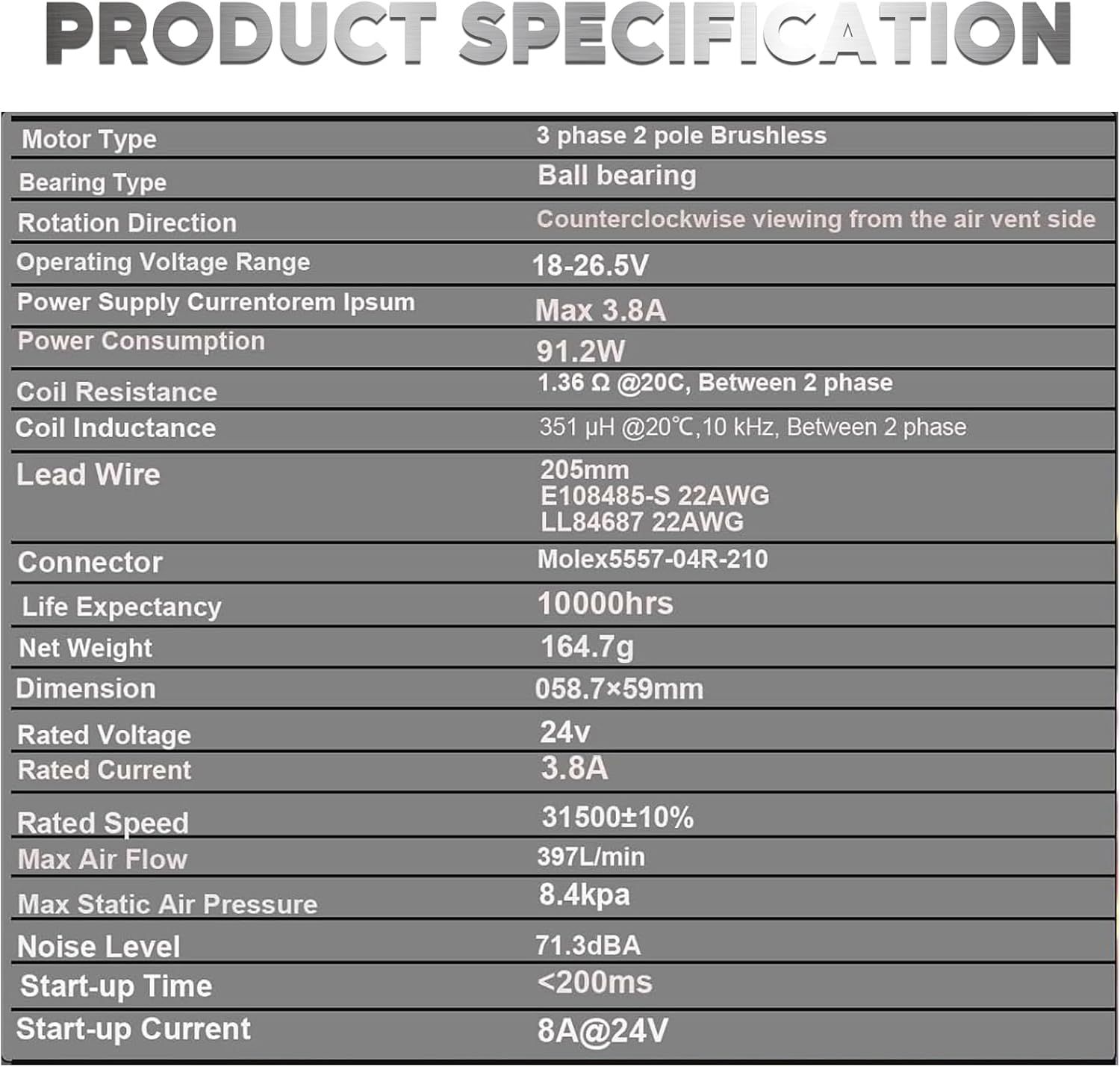
3-phase 2-pole CPAP pump with 6HC?posted in Duet Hardware and wiring
Is it possible to use such a blower for cooling?
-
RE: Bug report: object cancellation causes ugly things to happenposted in General Discussion
@droftarts yes, I realized that later, let me upload it again.
-
RE: Bug report: object cancellation causes ugly things to happenposted in General Discussion
@droftarts I'm using PrusaSlicer. I'll slice up a little print and upload it.
-
RE: Bug report: object cancellation causes ugly things to happenposted in General Discussion
@gnydick Any update here? This is still happening. I'm running even gentle prints with lower accel and speeds.
Duet 3 MB6HC MB6HC 3.5.3 Duet 3 Expansion EXP3HC EXP3HC 3.5.3 Duet 3 Expansion TOOL1LC TOOL1LC 3.5.3 Duet 3 Expansion TOOL1LC TOOL1LC 3.5.3 Duet 3 Expansion TOOL1LC TOOL1LC 3.5.3 Duet 3 Expansion TOOL1LC TOOL1LC 3.5.3 Duet Software Framework DSF 3.5.3 Duet Web Control DWC 3.5.3 -
RE: pid tuning never endsposted in General Discussion
@Phaedrux over an hour after it hits phase 4 and has settled
-
RE: Input shaping on large mass print headposted in Tuning and tweaking
@T3P3Tony I think it requires an enhancement to the input shaping plugin to configure the sample time.
-
pid tuning never endsposted in General Discussion
I'm using 6hc + tool distro board + 1Lc with
M303 T0 S320and it never finishes. The graph is extremely smooth and consistent. It just never ends after getting to the fourth phase. -
RE: 3 fans on tool board 1lc?posted in Duet Hardware and wiring
@dwuk I just ended up getting blowers without tachs and wiring them up in parallel.
-
RE: Printer is possessed, tool docked during printposted in General Discussion
Thanks, @mikeabuilder. I do have cats, and possibly a ghost. It turns out that there was an actual tool change in the gcode somewhere. I was only using tool 1 out of 0-3, but the slicer assumed something needed another tool even though nothing was assigned to another extruder.
So, no more emergency or possession.
Thanks again
-
Printer is possessed, tool docked during printposted in General Discussion
IGNORE THIS POST no more help needed
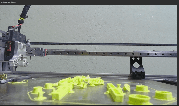
I checked my print progress through the webcam on my printer and saw that there was no tool mounted on the toolhead, but it was still printing.
But, it gets VERY strange.
- Some of the pieces of the print were knocked loose, actually dislodged
- It should have dislodged the build plate from the magnetic bed, but it didn't.
- The current adhesion on the print bed too good, a collision that could have dislodged those pieces should have easily ripped the flex plate off of the bed.
- The locking pin on the toolhead is now in the correct unloaded position
- The tool is docked correctly
- All of the tools are docked correctly
- The dislodged pieces of the print are not in-line with the unloading procedure for the tool
- The controller knows there is no tool selected
- Each tool has a docking sensor for safety
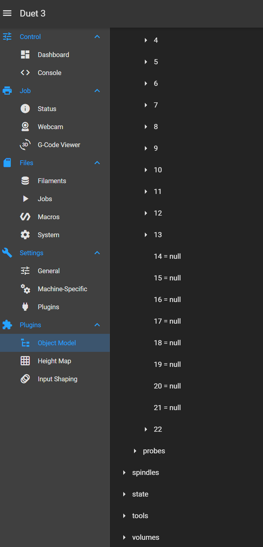
- T0 - T3 are gpin 20 - 23
T1was in use so it should be using gpin 21- In the attached screenshot you can see that sensors 20 & 21 are
null - Sensor 22 is there and has the correct value
- Sensor 23 doesn't exist
- console output attached as well showing only j22 exists
I'm truly at a loss for ideas.
-
RE: OK, not exactly wiring, but where can I buy wires in US??posted in Duet Hardware and wiring
@magnets99 also, I'm so confused about the industry. Jst-ph tops out at 2A on 24AWG, but my motors take up to 2.8A.
How/why are motors made with connectors that can't carry the current they're rated for?
-
RE: OK, not exactly wiring, but where can I buy wires in US??posted in Duet Hardware and wiring
@magnets99 thanks. Lots of good information there.
-
OK, not exactly wiring, but where can I buy wires in US??posted in Duet Hardware and wiring
I'm trying to find stepper motor cables that fit the 6HC, 20-16 AWG. Everything I can find is much too small and is not crimpable, even in the 18-22 AWG crimp terminals.
I'm ideally hoping to find pre-terminated cables where all I have to replace is the the driver end connector.
-
RE: config-user.g overwritten with config.g contentsposted in General Discussion
@T3P3Tony I can understand the thoughts on config-user.g not being a system file, so I'm guessing it was a DWC bug.
The config-user.g is good for settings you may want to frequently tweak after boot, that are safe to reload at any time. Having a
reload_config-usermacro usually accompanies it. I personally have a number of additional filesaxis-limits.g: I have kinematics that get tweaked frequently so i will reload that
tools.g: this sets all of the kinematic configs for the tools.
macros/tfree|tpre|tpost: these have all of the common movements for all of the tools. these macros take parameters so any movement lengths only need to be provided in thetfree_.g,tpre_.g, andtpost_.gfiles, like `M98 P"/macros/tools/tfree.g"It took me a lot of work to get this all working smoothly. But now I have a lot of safety measures built in with docking sensors, "coupler homed?", temperature thresholds.
Examples
tfree0.g
; tfree0.g

; Common routine
M98 P"/macros/tools/tfree" X3.0 Y20.0 ; X param is how far from the end of X axis to go to pick up the tool , Y param is absolute Y position to pick up the tool
tpre0.g
; tpre0.g

M98 P"/macros/tools/tpre" X3.0 Y20.0 ; move into position, same params as tfree
tpost0.g
; tpost0.g

M98 P"/macros/tools/tpost" A0.037 ; A param is pressure advance setting
M593 P"zvddd" F52.8 S.1 ; enable input shaping
and the macros they call
/macros/tools/tfree
; tfreeN
; called when tool N is freed
;

var t = state.currentTool
var heaterIndex = state.currentTool + 1
var x = param.X
var y = param.Y
var xMax = move.axes[0].max - var.x

var sensor_index = var.t + 10

var dock0 = sensors.gpIn[10].value
var dock1 = sensors.gpIn[11].value
var dock2 = sensors.gpIn[12].value
var dock3 = sensors.gpIn[13].value

var undockedTools = ""
var cancelMessage = "Too many undocked tools: "

if { var.dock0 == 0 }
    set var.undockedTools = var.undockedTools ^ "1"
    set var.cancelMessage = var.cancelMessage ^ "0"
if { var.dock1 == 0 }
    set var.undockedTools = var.undockedTools ^ "1"
    if #var.undockedTools > 0
        set var.cancelMessage = var.cancelMessage ^ ", "
    set var.cancelMessage = var.cancelMessage ^ "1"
if { var.dock2 == 0 }
    set var.undockedTools = var.undockedTools ^ "1"
    if #var.undockedTools > 0
        set var.cancelMessage = var.cancelMessage ^ ", "
    set var.cancelMessage = var.cancelMessage ^ "2"
if { var.dock3 == 0 }
    set var.undockedTools = var.undockedTools ^ "1"
    if #var.undockedTools > 0
        set var.cancelMessage = var.cancelMessage ^ ", "
    set var.cancelMessage = var.cancelMessage ^ "3"


if exists(param.S)
    set var.undockedTools = "1"

if #var.undockedTools > 1

    M291 P{var.cancelMessage}

else


    G60 S0
    if {heat.heaters[var.heaterIndex].current} > 170
        G1 E-5 F6000
        G91
        G1 Z1
        G90

    G53 G1 Y{var.y} F12000
    G53 G1 X380 F12000
    G53 G1 X{var.xMax} F2000

    M106 P{var.t + 1} S0

    ;Open Coupler
    M98 P"/macros/tool_unlock"


    ;Move Out
    G53 G1 X380 F12000
    G53 G1 X330 F12000
    M400

    M593 P"none"  ; disable input shaping
/macros/tools/tpre
; tpre
; called before tool 1 is selected

;WARNING! WARNING! WARNING! WARNING! WARNING! WARNING! WARNING! WARNING! WARNING! WARNING! WARNING! WARNING!
;if you are using non-standard length hotends ensure the bed is lowered enough BEFORE undocking the tool!
var t = state.nextTool
var heaterIndex = var.t + 1
var x = param.X
var y = param.Y
var xMax = move.axes[0].max - var.x


var dock0 = sensors.gpIn[10].value
var dock1 = sensors.gpIn[11].value
var dock2 = sensors.gpIn[12].value
var dock3 = sensors.gpIn[13].value

if { var.dock0 == 1 && var.dock1 == 1 && var.dock2 == 1 && var.dock3 == 1 }
	if tools[var.t].state != "active"
		var message = "Activating Tool " ^ var.t
		M118 S{var.message}
		M98 P"/macros/tools/safeZ"


		;Move In
		G53 G1 X300 F12000
		G53 G1 Y{var.y} F12000
		G53 G1 X380 F12000
		G53 G1 X{var.xMax} F1800
		M98 P"/macros/tool_lock"	;Close Coupler
		G53 G1 X397 F900

	M400

else
	T-1 P0
/macros/tools/tpost
; tpost0.g ; called after tool 0 has been selected var t = state.currentTool var sensorIndex = state.currentTool + 10 var heaterIndex = state.currentTool + 1 var a = param.A var docked = sensors.gpIn[var.sensorIndex].value if exists(param.S) set var.docked = 0 if var.docked == 0 G91 G1 X-60 F1800 G1 X-40 F6000 G90 M116 P{var.t} if {heat.heaters[var.heaterIndex].current} > 170 M98 P"/macros/tools/wipe_tall" else G91 G1 X-100 F6000 G90 M400 M572 D{var.t} S{var.a} ; enable fan if it was running M106 R2 else T-1 P0 -
config-user.g overwritten with config.g contentsposted in General Discussion
I don't know what happened, but things started acting funny, I checked and my config-user.g file now has older contents of config.g. This isn't manual error. I've not done any renaming, full copy & paste, etc. I literally just homed my machine 20 minutes ago, and now it doesn't work because there is no more probe defined as it was in config-user.g.
So now I've lost my lead screw positions, mesh config, z probe, etc.
I'm on 3.5.3 + SBC, duet 6HC