Duet3D Logo Duet3D
    • Tags
    • Documentation
    • Order
    • Register
    • Login
    1. Home
    2. Jman3
    3. Posts
    • Profile
    • Following 1
    • Followers 0
    • Topics 4
    • Posts 21
    • Best 4
    • Controversial 0
    • Groups 0

    Posts made by Jman3

    • RE: Help with filament sensor

      Sorry for the late update I ran into some other issues I needed to take care of.

      So it looks like I got this working after I fixed a few issues. I managed to print a temp tower without issue, maybe I'll have problems in the future with other prints.

      1. Installed a mount close by the extruder (around 1" of distance between the sprite pro extruder
      2. Removed my filament-error.g (it was trying to pause then run filament-error.g)
      3. Used the BTT recomended g-code but adjusted E value to 22
      4. Changed my retraction speed to 60mm/s

      Here is the g-code I'm using

      ;  Filament Monitor (Filament Runout Sensor, Big Tree Tech - Smart Filament Sensor V2)
      M591 D0 P7 C"io0.in" L2.88 R75:125 S2 E22   
      
      posted in Third-party add-ons
      Jman3undefined
      Jman3
    • RE: Help with over-extrusion

      @Phaedrux I repeated the e step calibration 3 or 4 times so I feel pretty good about it.

      I posted the same thing on another site and someone mentioned that retraction settings can cause this same issue. I double checked my settings and I had an override on my ABS settings that was still 2mm. I lowered it to .5 then tested it last night and the print looked perfect this morning. So the issue was my retraction setting surprisingly.

      posted in Tuning and tweaking
      Jman3undefined
      Jman3
    • Help with over-extrusion

      I have an Ender 3 running RepRap firmware on a Duet 3 mini 5+ and I recently installed a direct drive sprite pro extruder. I have been going through commissioning and calibration and it seems like I'm over-extruding even after the e-step calibration (423.2), and flow rate calibration (.82). I thought it might be pressure advance so I commented it out of my firmware and set it to .03 in ORCA slicer.

      I'm printing with ABS that has worked fine with the old bowden setup. See images for details.

      Any ideas on how to address this issue?

      52062491-8b53-4d0f-8e84-f2f498ab7fa7-image.png

      3ecfb1ea-34f7-498a-acf7-98ad53a1acd9-image.png

      25ff9abc-5377-4654-9b3f-8601df9a2df9-image.png

      posted in Tuning and tweaking
      Jman3undefined
      Jman3
    • RE: Help with filament sensor

      So adding M25 caused it to stop like I wanted but it seems like it's trying to run pause.g and filament-error.g consecutively because it raises up 5mm 2X. I'll see about troubleshooting more tomorrow or this weekend.

      posted in Third-party add-ons
      Jman3undefined
      Jman3
    • RE: Help with filament sensor

      @Phaedrux Sorry you are correct it should be filament-error.g. My filament-error.g is listed in the original post.

      I looked over the documentation again and it looks like I forgot to include M25 to pause the print. I'm going to play around with it tonight.

      posted in Third-party add-ons
      Jman3undefined
      Jman3
    • RE: Help with filament sensor

      @jay_s_uk So I updated accordingly but I'm still getting no calibration data out of "M590 D0"

      All I get is: "Pulse-type filament monitor on pin io0.in, enabled always, 2.880mm/pulse, allowed movement 75% to 125%, check every 9.0mm, no calibration data"

      I am also getting a strange problem during my print where it looks like it hits a filament error but it just runs my filament-monitor.g without stopping it tries to go right back to printing without going back to its z position. Do i need to change my filament-monitor.g?

      posted in Third-party add-ons
      Jman3undefined
      Jman3
    • RE: Help with filament sensor

      @jay_s_uk so in my config.g it should be "M591 D7 P7..."?

      https://docs.duet3d.com/User_manual/Reference/Gcodes#m591-configure-filament-sensing

      Shows that D is the extruder setting and I have mine set to driver 4. Why should it be 7 instead of 4?

      posted in Third-party add-ons
      Jman3undefined
      Jman3
    • Help with filament sensor

      Hello, I am trying to install a BTT SFS v2.0 to my Duet 3 mini 5+ but I am not getting any errors or pausing when the filament runs out. The sensor looks like its working properly as the lights are pulsing or changing color when they should (blinks as filament moves through and turns red when no filament is present). I only want the pulse signal as it can catch a jam and if filament runs out it should produce the same error. So I have attached the signal from that pin to io0.in and configured my firmware according to the instructions (https://docs.duet3d.com/User_manual/Connecting_hardware/Sensors_filament).

      I'm sure I'm missing something silly but after reading through the other threads related to the BTT SFS V1.0 I didn't get any answers. Does anyone have ideas on what the issue is or how to troubleshoot it?

      note from changlog on firemware 3.5.1: "Filament monitors can now be activated even when not printing from SD card, by using S2 in the M591 command instead of S1; but in this case a filament-error event macro must be defined because the default action (pause the print) won't work unless printing from SD card"

      Because of this i made filament-error.g and copied over the gcode from pause.g

      Filament Sensor Details: https://github.com/bigtreetech/smart-filament-detection-module
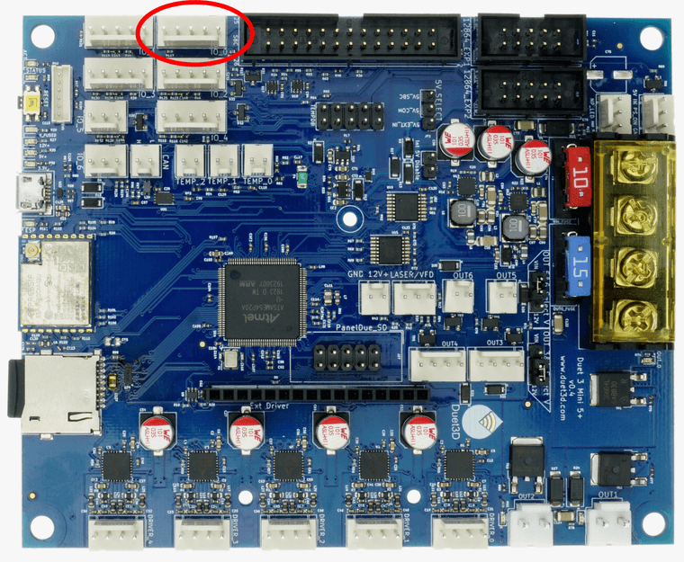
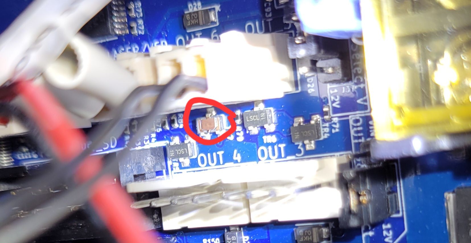
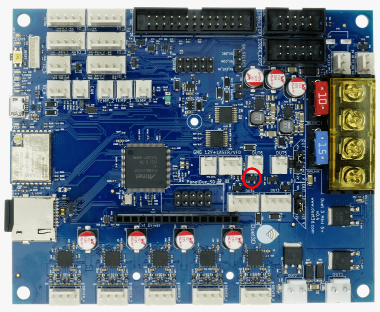
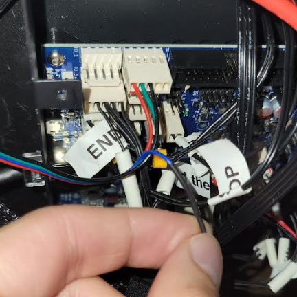
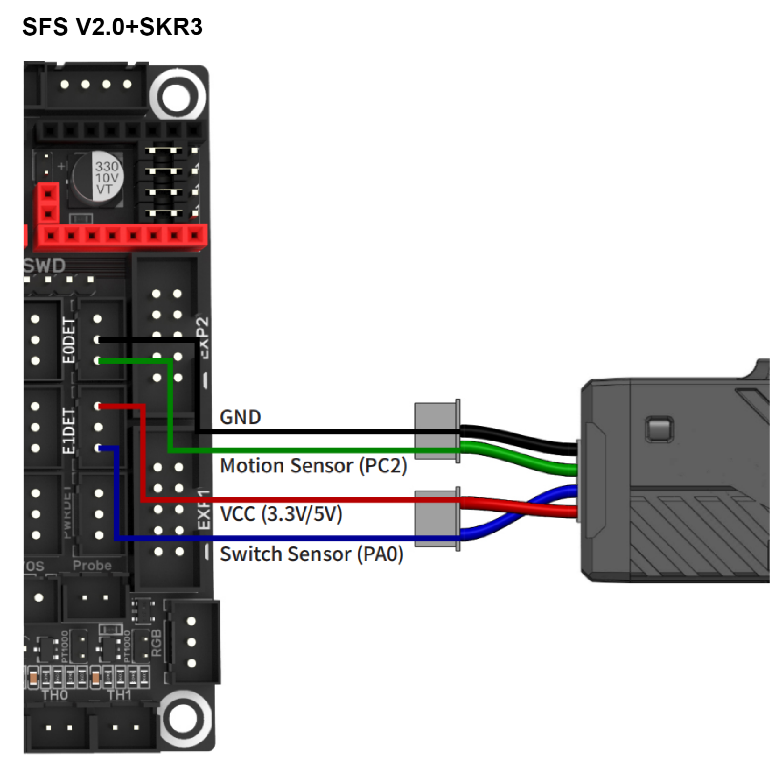
      28e77afe-b708-4180-857e-278cd6f0fb35-image.png

      io pin connection:
      b0b1fb0d-4fca-4b07-b6d3-2cab08eca030-image.png

      345b86a1-b40b-4035-9d50-3add7573ef18-image.png

      Firmware version: 3.5.2

      filament-error.g

      ; filament-error.g
      ; called when runout sensor is tripped
      ;
      ; generated on Mon Jul 29 2024
      ; copy of pause.g
      
      M83            ; relative extruder moves
      G1 E-10 F3600  ; retract 10mm of filament
      G91            ; relative positioning
      G1 Z5 F360     ; lift Z by 5mm
      G90            ; absolute positioning
      G1 X0 Y0 F6000 ; go to X=0 Y=0


      Config.g:

      ; Configuration file for Duet 3 Mini 5+ (firmware version 3.5.2)
      ; executed by the firmware on start-up
      ;
      ; generated by RepRapFirmware Configuration Tool v3.3.16 on Tue Nov 14 2023 20:04:52 GMT-0600 (Central Standard Time)
      ; Updated after the sprite pro extruder install v3.5.2 on Sunday Jul 28 2024 9:21pm
      
      ; General preferences
      G90                                                ; send absolute coordinates...
      M83                                                ; ...but relative extruder moves
      M550 P"My Printer"                                 ; set printer name
      
      ; Network
      M552 P0.0.0.0 S1                                   ; enable network and acquire dynamic address via DHCP
      M586 P0 S1                                         ; enable HTTP
      M586 P1 S0                                         ; disable FTP
      M586 P2 S0                                         ; disable Telnet
      
      ; Drives
      M569 P0.0 S0 D3 V0                                 ; physical drive 0.0 goes backwards, D3 = stealthchop (this works well with low motor torques)
      M569 P0.1 S0 D3 V0                                 ; physical drive 0.1 goes backwards, D3 = stealthchop (this works well with low motor torques)
      M569 P0.2 S1 D3 V0                                 ; physical drive 0.2 goes forwards, D3 = stealthchop (this works well with low motor torques)
      M569 P0.4 S0 D3 V0                                 ; physical drive 0.4 goes backwards, D3 = stealthchop (this works well with low motor torques)
      M584 X0.0 Y0.1 Z0.2 E0.4                           ; set drive mapping
      M350 X16 Y16 Z16 E16 I1                            ; configure microstepping with interpolation
      M92 X80.00 Y80.00 Z400.00 E423.2                  ; set steps per mm
      M566 X900.00 Y900.00 Z60.00 E300.00                ; set maximum instantaneous speed changes (mm/min)
      M203 X6000.00 Y6000.00 Z600.00 E3600.00            ; set maximum speeds (mm/min)
      M201 X500.00 Y500.00 Z200.00 E2500.00              ; set accelerations (mm/s^2)
      M906 X600 Y600 Z600 E900 I30                       ; set motor currents (mA) and motor idle factor in per cent
      M84 S30                                            ; Set idle timeout
      
      ; Axis Limits
      M208 X0 Y0 Z0 S1                                   ; set axis minima
      M208 X215 Y235 Z250 S0                             ; set axis maxima
      
      ; Endstops
      M574 X1 S1 P"io5.in"                               ; configure switch-type (e.g. microswitch) endstop for low end on X via pin io5.in
      M574 Y1 S1 P"io6.in"                               ; configure switch-type (e.g. microswitch) endstop for low end on Y via pin io6.in
      M574 Z1 S2                                         ; configure Z-probe endstop for low end on Z
      
      ;  Filament Monitor (Filament Runout Sensor, Big Tree Tech - Smart Filament Sensor V2)
      M591 D4 P7 C"io0.in" L2.88 R75:125 E9 S2           ; filament monitor M591: configure filament sensor, D4: extruder4, P7: type pulse, C"io0.in" (pinout),L2.88: filament per pulse (mm), R75:125: sensitivity 25% of length, E9: sampled 9mm, S2 activated even when not printing from SD card, by using S2 in the M591 command instead of S1
      
      ; Z-Probe
      M950 S0 C"io3.out"                                 ; create servo pin 0 for BLTouch
      M558 P9 C"io3.in" H5 F120 T6000                    ; set Z probe type to bltouch and the dive height + speeds
      G31 P25 X-48 Y0 Z2.10                           ; set Z probe trigger value, offset and trigger height
      M557 X0:165 Y10:225 S41.25                           ; define mesh grid
      
      ; Heaters
      M308 S0 P"temp0" Y"thermistor" T98801 B4185        ; configure sensor 0 as thermistor on pin temp0
      M950 H0 C"out0" T0                                 ; create bed heater output on out0 and map it to sensor 0
      M307 H1 R3.120 K0.662:0.254 D5.36 E1.35 S1.00 B0 V23.7     ; disable bang-bang mode for the bed heater and set PWM limit, added Tuning here Tuned Jul/28/2024 (Sprite Pro)
      M140 H0                                            ; map heated bed to heater 0
      M143 H0 S120                                       ; set temperature limit for heater 0 to 120C
      M308 S1 P"temp1" Y"thermistor" T98801 B4185        ; configure sensor 1 as thermistor on pin temp1
      M950 H1 C"out1" T1                                 ; create nozzle heater output on out1 and map it to sensor 1
      M307 H0 R0.314 K0.257:0.000 D4.50 E1.35 S1.00 B0           ; disable bang-bang mode for heater  and set PWM limit, added Tuning here
      M143 H1 S310                                       ; set temperature limit for heater 1 to 310C
      
      ; Fans
      M950 F0 C"out5" Q500                               ; create fan 0 on pin out5 and set its frequency
      M106 P0 C"Part Cooling" S0 H-1                     ; set fan 0 name and value. Thermostatic control is turned off
      M950 F1 C"out3" Q500                               ; create fan 1 on pin out3 and set its frequency
      M106 P1 C"Heat Block HotEnd" S1 H1 T45             ; set fan 1 name and value. Thermostatic control is turned on
      
      ; Tools
      M563 P0 S"HotEnd" D0 H1 F0                         ; define tool 0
      G10 P0 X0 Y0 Z0                                    ; set tool 0 axis offsets
      G10 P0 R0 S0                                       ; set initial tool 0 active and standby temperatures to 0C
      
      ; Custom settings
      M204 P600 T2000				                                ; Set accelerations (mm/s^2) for print and travel moves
      M912 P0 S-13 				                                  ; CPU Temperature calibration
      M572 D0 S0.35				                                  ; Pressure advance
      M207 S6.5 R0.0 F2800 T4800 z0.0                    ; Retraction
      M280 P0 S160				                                   ; Clear any alarms
      M402						                                         ; Retract Pin
      
      ; Miscellaneous
      M501                                               ; load saved parameters from non-volatile memory
      M911 S21 R23 P"M913 X0 Y0 G91 M83 G1 Z3 E-5 F1000" ; set voltage thresholds and actions to run on power loss
      T0                                                 ; select first tool


      posted in Third-party add-ons
      Jman3undefined
      Jman3
    • RE: Fan Error - Inverted

      It turns out I must have burned up my Out6 while poking around with a multimeter. I switched to Out3 and the hotend fan thermostatic control is working as it should now.

      posted in Duet Hardware and wiring
      Jman3undefined
      Jman3
    • RE: Fan Error - Inverted

      So did this IC burnout?

      my board
      1000007985.jpg

      Documented picture
      7ab138a1-febc-42b2-a99a-e4fbe1a3ba0c-image.png

      posted in Duet Hardware and wiring
      Jman3undefined
      Jman3
    • RE: Fan Error - Inverted

      @dc42 No, it's a 2 wire.

      posted in Duet Hardware and wiring
      Jman3undefined
      Jman3
    • Fan Error - Inverted

      Hello,

      Background: I recently upgraded my Ender 3 pro with a Sprite Pro Extruder and added 5015 blower fans. I have a Duet 3 mini 5+ ethernet and my original hotend worked as expected.

      Problem: While comissioning I noticed that my hotend fan was on at room temp and turned off when the thermostatic control is supposed to turn it on. I messed around with the settings changing it to a non thermostatic control and it seems inverted. When I turn it on its off and when I turn it off its on. I feel like there is something simple that I am missing in my .config but reading through the documentation and troublshooting hasen't yeilded anything. I also searched around on the forum and didn't find a similar post.

      My next plan was just to go from Out6 to Out3 to see if I have a hardware issue.

      Anyone have ideas for what might be happening?

      .config

      ; Configuration file for Duet 3 Mini 5+ (firmware version 3.3)
      ; executed by the firmware on start-up
      ;
      ; generated by RepRapFirmware Configuration Tool v3.3.16 on Tue Nov 14 2023 20:04:52 GMT-0600 (Central Standard Time)
      
      ; General preferences
      G90                                                ; send absolute coordinates...
      M83                                                ; ...but relative extruder moves
      M550 P"My Printer"                                 ; set printer name
      
      ; Network
      M552 P0.0.0.0 S1                                   ; enable network and acquire dynamic address via DHCP
      M586 P0 S1                                         ; enable HTTP
      M586 P1 S0                                         ; disable FTP
      M586 P2 S0                                         ; disable Telnet
      
      ; Drives
      M569 P0.0 S0 D3 V0                                 ; physical drive 0.0 goes backwards, D3 = stealthchop (this works well with low motor torques)
      M569 P0.1 S0 D3 V0                                 ; physical drive 0.1 goes backwards, D3 = stealthchop (this works well with low motor torques)
      M569 P0.2 S1 D3 V0                                 ; physical drive 0.2 goes forwards, D3 = stealthchop (this works well with low motor torques)
      M569 P0.4 S0 D3 V0                                 ; physical drive 0.4 goes backwards, D3 = stealthchop (this works well with low motor torques)
      M584 X0.0 Y0.1 Z0.2 E0.4                           ; set drive mapping
      M350 X16 Y16 Z16 E16 I1                            ; configure microstepping with interpolation
      M92 X80.00 Y80.00 Z400.00 E143.9                  ; set steps per mm
      M566 X900.00 Y900.00 Z60.00 E300.00                ; set maximum instantaneous speed changes (mm/min)
      M203 X6000.00 Y6000.00 Z600.00 E3600.00            ; set maximum speeds (mm/min)
      M201 X500.00 Y500.00 Z200.00 E2500.00              ; set accelerations (mm/s^2)
      M906 X600 Y600 Z600 E900 I30                       ; set motor currents (mA) and motor idle factor in per cent
      M84 S30                                            ; Set idle timeout
      
      ; Axis Limits
      M208 X0 Y0 Z0 S1                                   ; set axis minima
      M208 X235 Y235 Z260 S0                             ; set axis maxima
      
      ; Endstops
      M574 X1 S1 P"io5.in"                               ; configure switch-type (e.g. microswitch) endstop for low end on X via pin io5.in
      M574 Y1 S1 P"io6.in"                               ; configure switch-type (e.g. microswitch) endstop for low end on Y via pin io6.in
      M574 Z1 S2                                         ; configure Z-probe endstop for low end on Z
      
      ; Z-Probe
      M950 S0 C"io3.out"                                 ; create servo pin 0 for BLTouch
      M558 P9 C"io3.in" H5 F120 T6000                    ; set Z probe type to bltouch and the dive height + speeds
      G31 P25 X-44 Y-17 Z0.65                           ; set Z probe trigger value, offset and trigger height
      M557 X30:230 Y30:230 S50                           ; define mesh grid
      
      ; Heaters
      M308 S0 P"temp0" Y"thermistor" T98801 B4185        ; configure sensor 0 as thermistor on pin temp0
      M950 H0 C"out0" T0                                 ; create bed heater output on out0 and map it to sensor 0
      M307 H1 R2.641 K0.738:0.011 D4.18 E1.35 S1.00 B0 V23.8     ; disable bang-bang mode for the bed heater and set PWM limit, added Tuning here
      M140 H0                                            ; map heated bed to heater 0
      M143 H0 S120                                       ; set temperature limit for heater 0 to 120C
      M308 S1 P"temp1" Y"thermistor" T98801 B4185        ; configure sensor 1 as thermistor on pin temp1
      M950 H1 C"out1" T1                                 ; create nozzle heater output on out1 and map it to sensor 1
      M307 H0 R0.314 K0.257:0.000 D4.50 E1.35 S1.00 B0           ; disable bang-bang mode for heater  and set PWM limit, added Tuning here
      M143 H1 S260                                       ; set temperature limit for heater 1 to 260C
      
      ; Fans
      M950 F0 C"out5" Q500                               ; create fan 0 on pin out5 and set its frequency
      M106 P0 C"Part Cooling" S0 H-1                     ; set fan 0 name and value. Thermostatic control is turned off
      M950 F1 C"out6" Q500                               ; create fan 1 on pin out6 and set its frequency
      M106 P1 C"Heat Block HotEnd" S1 H1 T45             ; set fan 1 name and value. Thermostatic control is turned on
      
      ; Tools
      M563 P0 S"HotEnd" D0 H1 F0                         ; define tool 0
      G10 P0 X0 Y0 Z0                                    ; set tool 0 axis offsets
      G10 P0 R0 S0                                       ; set initial tool 0 active and standby temperatures to 0C
      
      ; Custom settings
      M204 P600 T2000				                                ; Set accelerations (mm/s^2) for print and travel moves
      M912 P0 S-13 				                                  ; CPU Temperature calibration
      M572 D0 S0.35				                                  ; Pressure advance
      M207 S6.5 R0.0 F2800 T4800 z0.0                    ; Retraction
      M280 P0 S160				                                   ; Clear any alarms
      M402						                                         ; Retract Pin
      
      ; Miscellaneous
      M501                                               ; load saved parameters from non-volatile memory
      M911 S21 R23 P"M913 X0 Y0 G91 M83 G1 Z3 E-5 F1000" ; set voltage thresholds and actions to run on power loss
      T0                                                 ; select first tool
      
      posted in Duet Hardware and wiring
      Jman3undefined
      Jman3
    • RE: Help, cannot connect via USB

      @droftarts Thank you so much for the help! I'm printing and things are working well!

      Screenshot_20231123_115030_Gallery.jpg

      posted in Duet Hardware and wiring
      Jman3undefined
      Jman3
    • RE: Help, cannot connect via USB

      @droftarts

      So it looks like the original config.g that was on the sd card didn't get replaced for some reason and I replaced it with my config.g and everything seems to show up on the DWC now but my stepper motors make a loud teapot whistle noise whenever they are activated.

      My situation sounds very similar to this thread but non of the solutions discussed there seem to apply to my printer. (https://forum.duet3d.com/topic/29080/duet-3-mini-5-screeching-noise-when-moving-stepper-motors/2)

      Any ideas on why my motors have this issue? The motors seem to move in the correct direction and distance they just make this terrible noise that makes me think something is wrong.

      ; Configuration file for Duet 3 Mini 5+ (firmware version 3.3)
      ; executed by the firmware on start-up
      ;
      ; generated by RepRapFirmware Configuration Tool v3.3.16 on Tue Nov 14 2023 20:04:52 GMT-0600 (Central Standard Time)
      
      ; General preferences
      G90                                                ; send absolute coordinates...
      M83                                                ; ...but relative extruder moves
      M550 P"My Printer"                                 ; set printer name
      
      ; Network
      M552 P0.0.0.0 S1                                   ; enable network and acquire dynamic address via DHCP
      M586 P0 S1                                         ; enable HTTP
      M586 P1 S0                                         ; disable FTP
      M586 P2 S0                                         ; disable Telnet
      
      ; Drives
      M569 P0.0 S0                                       ; physical drive 0.0 goes backwards
      M569 P0.1 S0                                       ; physical drive 0.1 goes backwards
      M569 P0.2 S1                                       ; physical drive 0.2 goes forwards
      M569 P0.4 S0                                       ; physical drive 0.4 goes backwards
      M584 X0.0 Y0.1 Z0.2 E0.4                           ; set drive mapping
      M350 X16 Y16 Z16 E16 I1                            ; configure microstepping with interpolation
      M92 X80.00 Y80.00 Z400.00 E93.00                   ; set steps per mm
      M566 X900.00 Y900.00 Z60.00 E300.00                ; set maximum instantaneous speed changes (mm/min)
      M203 X6000.00 Y6000.00 Z600.00 E3600.00            ; set maximum speeds (mm/min)
      M201 X500.00 Y500.00 Z200.00 E2500.00              ; set accelerations (mm/s^2)
      M906 X600 Y600 Z600 E900 I30                       ; set motor currents (mA) and motor idle factor in per cent
      M84 S30                                            ; Set idle timeout
      
      ; Axis Limits
      M208 X0 Y0 Z0 S1                                   ; set axis minima
      M208 X235 Y235 Z260 S0                             ; set axis maxima
      
      ; Endstops
      M574 X1 S1 P"io5.in"                               ; configure switch-type (e.g. microswitch) endstop for low end on X via pin io5.in
      M574 Y1 S1 P"io6.in"                               ; configure switch-type (e.g. microswitch) endstop for low end on Y via pin io6.in
      M574 Z1 S2                                         ; configure Z-probe endstop for low end on Z
      
      ; Z-Probe
      M950 S0 C"io3.out"                                 ; create servo pin 0 for BLTouch
      M558 P9 C"io3.in" H5 F120 T6000                    ; set Z probe type to bltouch and the dive height + speeds
      G31 P500 X-44 Y-17 Z2.5                            ; set Z probe trigger value, offset and trigger height
      M557 X20:200 Y20:200 S20                           ; define mesh grid
      
      ; Heaters
      M308 S0 P"temp0" Y"thermistor" T98801 B4185        ; configure sensor 0 as thermistor on pin temp0
      M950 H0 C"out0" T0                                 ; create bed heater output on out0 and map it to sensor 0
      M307 H1 R2.641 K0.738:0.011 D4.18 E1.35 S1.00 B0 V23.8     ; disable bang-bang mode for the bed heater and set PWM limit, added Tuning here
      M140 H0                                            ; map heated bed to heater 0
      M143 H0 S120                                       ; set temperature limit for heater 0 to 120C
      M308 S1 P"temp1" Y"thermistor" T98801 B4185        ; configure sensor 1 as thermistor on pin temp1
      M950 H1 C"out1" T1                                 ; create nozzle heater output on out1 and map it to sensor 1
      M307 H0 R0.314 K0.257:0.000 D4.50 E1.35 S1.00 B0           ; disable bang-bang mode for heater  and set PWM limit, added Tuning here
      M143 H1 S260                                       ; set temperature limit for heater 1 to 260C
      
      ; Fans
      M950 F0 C"out5" Q500                               ; create fan 0 on pin out5 and set its frequency
      M106 P0 C"Part Cooling" S0 H-1                     ; set fan 0 name and value. Thermostatic control is turned off
      M950 F1 C"out6" Q500                               ; create fan 1 on pin out6 and set its frequency
      M106 P1 C"Heat Block HotEnd" S1 H1 T45             ; set fan 1 name and value. Thermostatic control is turned on
      
      ; Tools
      M563 P0 S"HotEnd" D0 H1 F0                         ; define tool 0
      G10 P0 X0 Y0 Z0                                    ; set tool 0 axis offsets
      G10 P0 R0 S0                                       ; set initial tool 0 active and standby temperatures to 0C
      
      ; Custom settings
      M204 P600 T2000				                                ; Set accelerations (mm/s^2) for print and travel moves
      M912 P0 S-13 				                                  ; CPU Temperature calibration
      M572 D0 S0.35				                                  ; Pressure advance
      M207 S6.5 R0.0 F2800 T4800 z0.0                    ; Retraction
      M280 P0 S160				                                   ; Clear any alarms
      M402						                                         ; Retract Pin
      
      ; Miscellaneous
      M501                                               ; load saved parameters from non-volatile memory
      M911 S21 R23 P"M913 X0 Y0 G91 M83 G1 Z3 E-5 F1000" ; set voltage thresholds and actions to run on power loss
      T0                                                 ; select first tool
      
      
      posted in Duet Hardware and wiring
      Jman3undefined
      Jman3
    • RE: Help, cannot connect via USB

      @droftarts

      I did want to ask another question related to this, let me know if this should be its own thread.

      After getting my configured SD card and I try to run my first check (Step 3 in https://docs.duet3d.com/en/How_to_guides/Commissioning).

      M98 P"config.g"

      I send it in the console I don't get anything back that I expect like what is shown in step 3. I also don't see any of my tools or anything in my dashboard.
      DWC_Dashboard.png

      I also have screenshots of my SYS and Firmware folders, they seem to line up with what I expect from the SD Card Document (https://docs.duet3d.com/User_manual/RepRapFirmware/SD_card)
      DWC_Sys.png DWC_Firmware.png

      Does this look right and why doesn't my DWC show any information from my printer?

      posted in Duet Hardware and wiring
      Jman3undefined
      Jman3
    • RE: Help, cannot connect via USB

      @droftarts

      Oh I think I understand, those were the files I put on the SD card originally I just saved a backup on my desktop. The files I showed are the same thing that is on my SD Card, I had copied them over after the configuration. Sorry for the confusion.

      posted in Duet Hardware and wiring
      Jman3undefined
      Jman3
    • RE: Help, cannot connect via USB

      @droftarts

      Okay good, I'm glad I followed that step about the PSU. Good call on the cable it looks like I had the wrong cable. I must have switched it out since last time and didn't realized the new cable wasn't transmitting data. I should have thought of that, thank you so much!

      This might be a dumb question but how would I access the actual card contents rather than just looking at what's in the folder?

      posted in Duet Hardware and wiring
      Jman3undefined
      Jman3
    • RE: Help, cannot connect via USB

      @jay_s_uk Okay thanks, I'll give this a shot today after work.

      posted in Duet Hardware and wiring
      Jman3undefined
      Jman3
    • RE: Help, cannot connect via USB

      @jay_s_uk Should it be plugged into the usb and the psu or only via usb? I'm a little worried to reset my board at this point. does that only remove the uf2 and I just have to add it back?

      posted in Duet Hardware and wiring
      Jman3undefined
      Jman3
    • RE: Help, cannot connect via USB

      @droftarts Thanks for the reply!

      So I have gone through that troubleshooting page. All the status lights on my board indicate that it is working fine. When I plug in the USB I unplug the power supply, should I have the power supply on while I have the USB plugged in? Also the second step of the troubleshooting page "Connect to a PC via USB and look for the port" I thought would apply to me but I can't get my device to show up in the device manager for either of my computers. And for the last step my USB cable is fine and non of the other ports on my computer show the Duet 3, I used this same setup when I initially updated the firmware and it worked as expected. Only after I wired everything up and configured the SD card do I have this issue.

      Here is a figure showing the other folders with content in my SD card. the other folders you mentioned are blank per the SD card structure.
      Duet 3 folders.png

      posted in Duet Hardware and wiring
      Jman3undefined
      Jman3