@droftarts Thanks. For now , it looks solved. I did a format with the SD_Card format tool. Checked: only one partition, put the files back and now it starts up again and find it's configfile. I will do the next days intensif testing with the stop and emergency stop and see if the problem still exists. But for now it looks the double partition was the culprit.
Best posts made by lazy_mosquito
-
RE: SD-card troubles 6XDposted in General Discussion
Latest posts made by lazy_mosquito
-
RE: SD-card troubles 6XDposted in General Discussion
@droftarts Thanks. For now , it looks solved. I did a format with the SD_Card format tool. Checked: only one partition, put the files back and now it starts up again and find it's configfile. I will do the next days intensif testing with the stop and emergency stop and see if the problem still exists. But for now it looks the double partition was the culprit.
-
RE: SD-card troubles 6XDposted in General Discussion
@droftarts I am also thinking it is something "soft" related. your explanation makes sense because on the pc I am using in my atelier I couldn't see the linux partition, so I was under the impression that only one partition existed. It is only when I opened the SD-card with the diskmanagement tool on my other pc that I saw the second partition and probably changed something, so it stayed visible for the windows 7 installation on the atelier PC. I will do a complete repartitioning and try again and come back after testing.
Thanks -
SD-card troubles 6XDposted in General Discussion
@droftarts and @Phaedrux as you suggested I started a new thread. Finally found some time to check out the SD-card reader on my 6xd.
Problem: Often (10% of the time?) when I stop my delta printer with the emergency stop in the web interface or with the STOP-button in PanelDue my config-file gets deleted and my delta is not starting up anymore. I have the idea (couldn't check it yet) that the panelDue STOP-button is more destructive. the web interface only deletes sometime the config-file, but I can just put it back and everything works again. This happened rather regularly because I am in the phase of finetuning my servos and very often have to shut down the machine with the emergency stop. I used two weeks ago for the first time the STOP-button in the PanelDue interface and this time not only the config-file disappeared but also the filesystem or the partitioning got messed up. i got it back in windows 11 via diskmanagement. I just got the filesystem corrected again, so i hope i can get this behavior reproduced.
Bought January 9, 2024 at 123-3d(dot)nl
As requested I connected via Yat to my board and run M115, M122, M22 and M21.
Please find the output in attachment Yat SD Card.txt
But you will find in this output that the SD-card is found and recognized.
But if I check the panelDue and click on the SD-card it says no files found. (does it show the files on the SD-card or only the one in the panelDue slot SD-card, which is not used by me)
It also doesn't start up the web interface, and this has almost to be for sure because it doesn't have access to the config file: no ip-adres, no homing option,...)
When I take out the SD-card, the structure of the SD-card seems altered. I made one partition as told in the manual. I named the SD-card/partition "Delta".
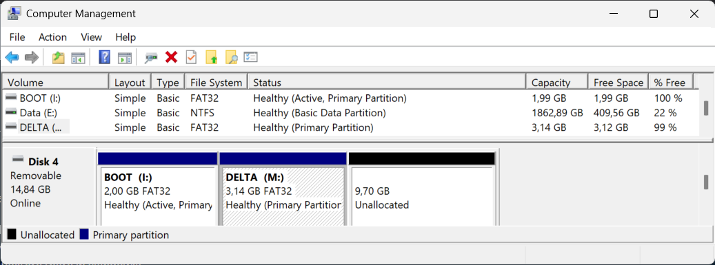
IN windows 7 (my atelier PC used for uploading files to my printer and where I created the partition originally) the Delta partition is not accessible anymore in explorer and the name is gone. There is also a new partition (made by duet3D?) called boot and here I find a similar file structure but in this file structure the config file is missing. If I go to disk management I can see now two partitions and an unallocated space of 9,7 GB
At home I have a windows 11 pc and there I can see both partitions and both are accessible.
So, it seems to me that duet is somehow altering the file structure of the SD-card and makes it unreadable in the process. I suspect it is booting from the boot partition but it can't find the config-file.
In attachment some screenshots of the content of the 2 sys-directories in the boot and the original partition (Delta). In the boot partition the configfile is missing.
further some photos of the soldering of the SD-card holder. They look ok.
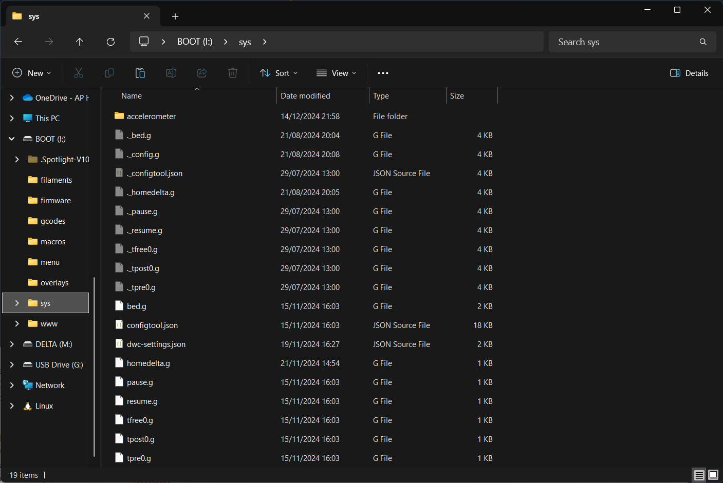
content of sys-map in new boot partition
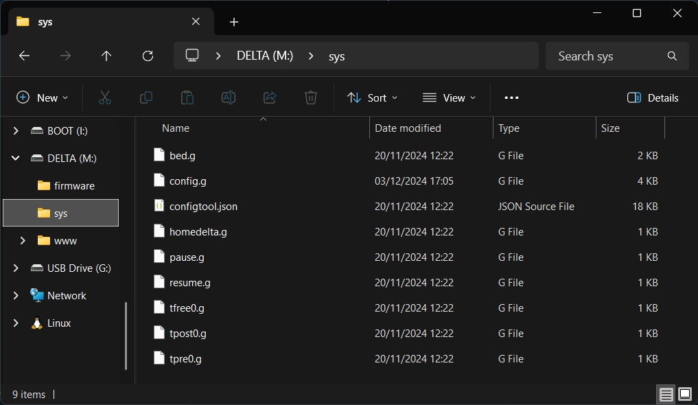
content of sys-map in original partition (Delta)
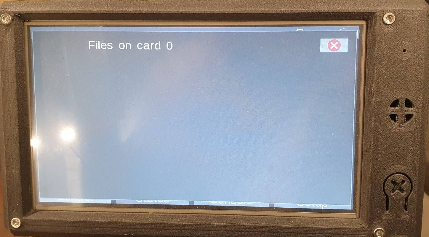
Empty SD card according the panel Due
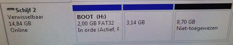
Diskmanagement windows 7
Diskmanagement windows 11
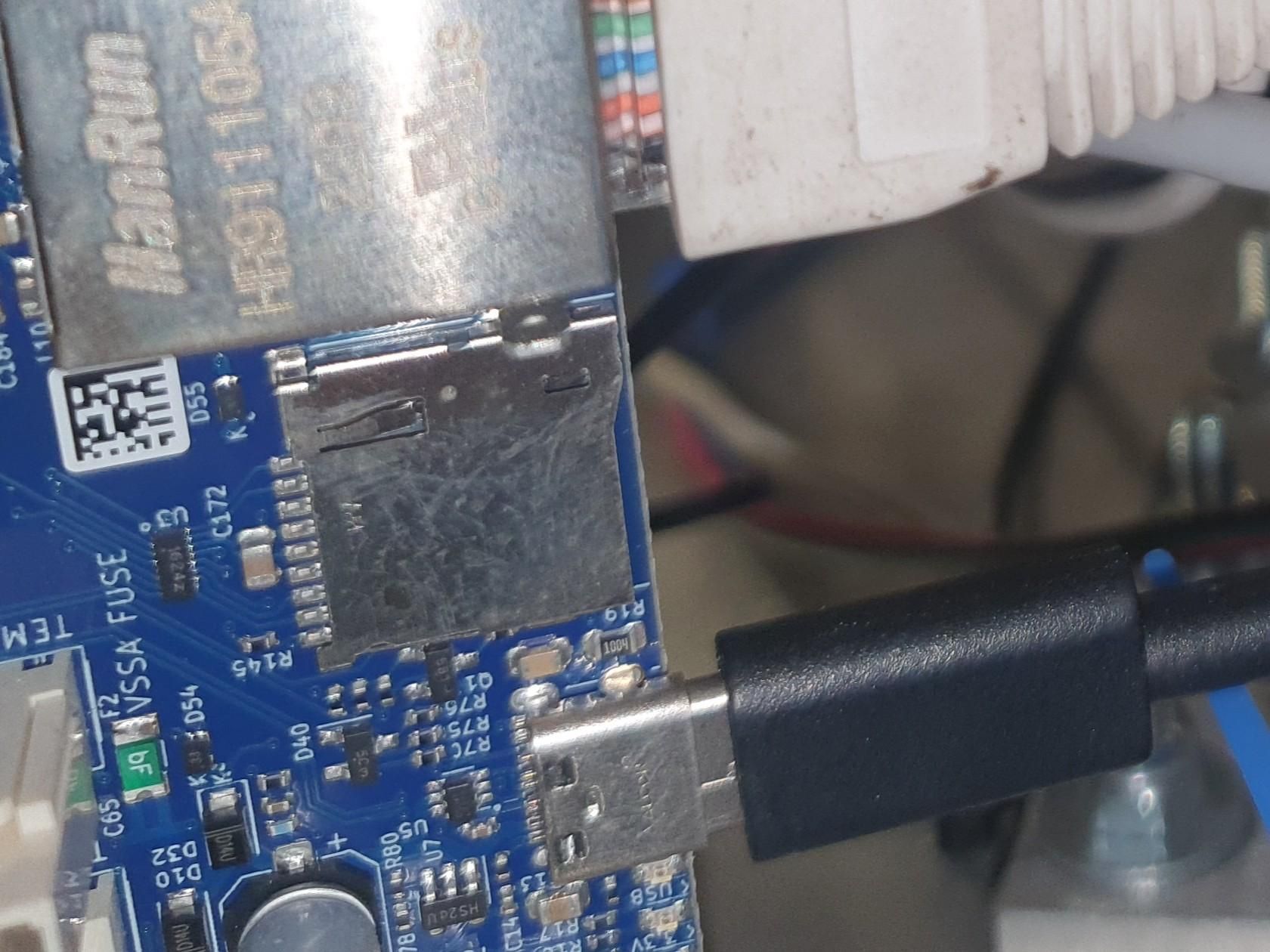
soldering 1
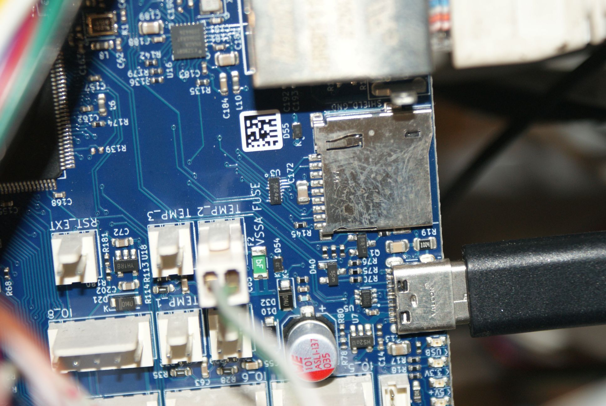
soldering 2
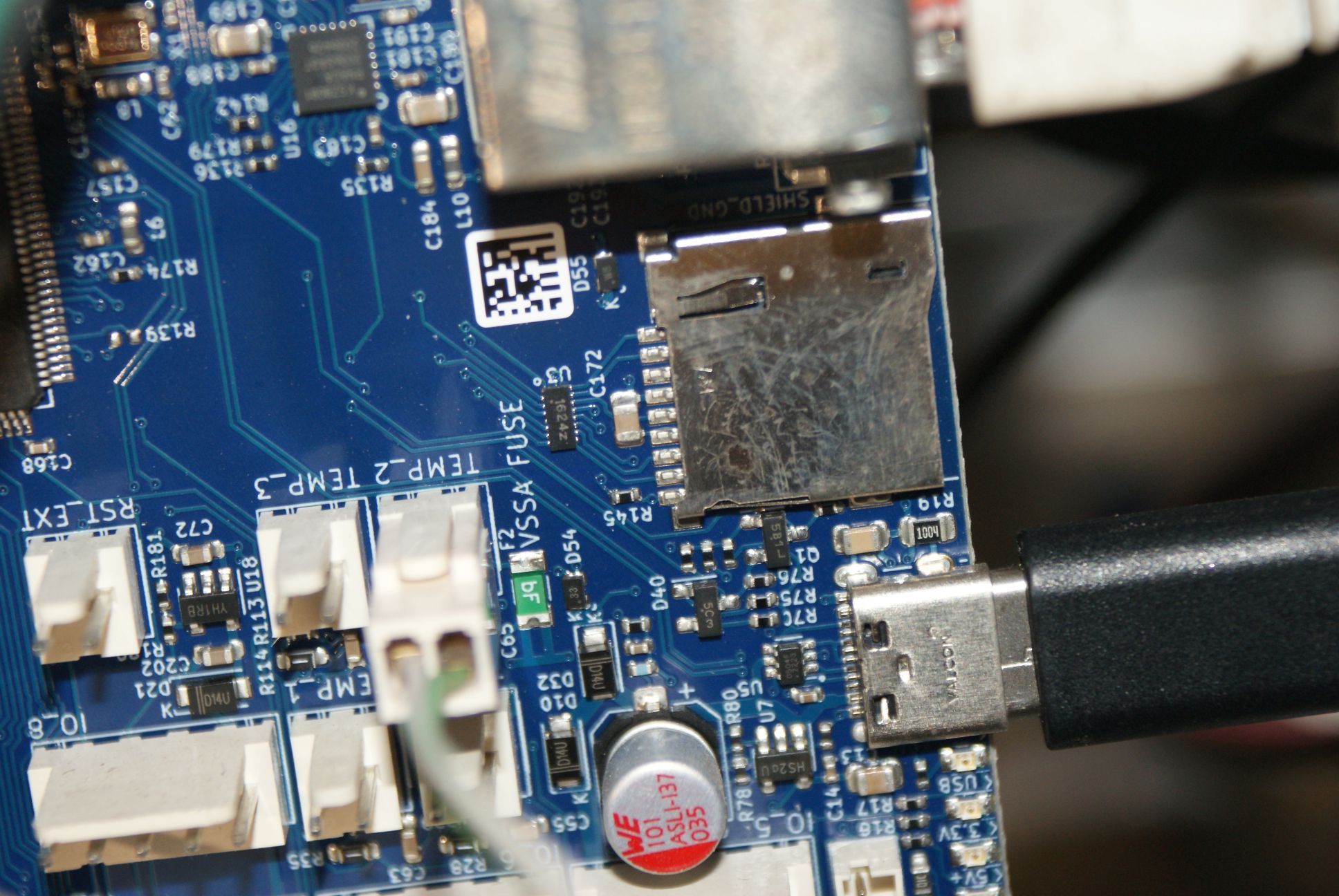
soldering 3
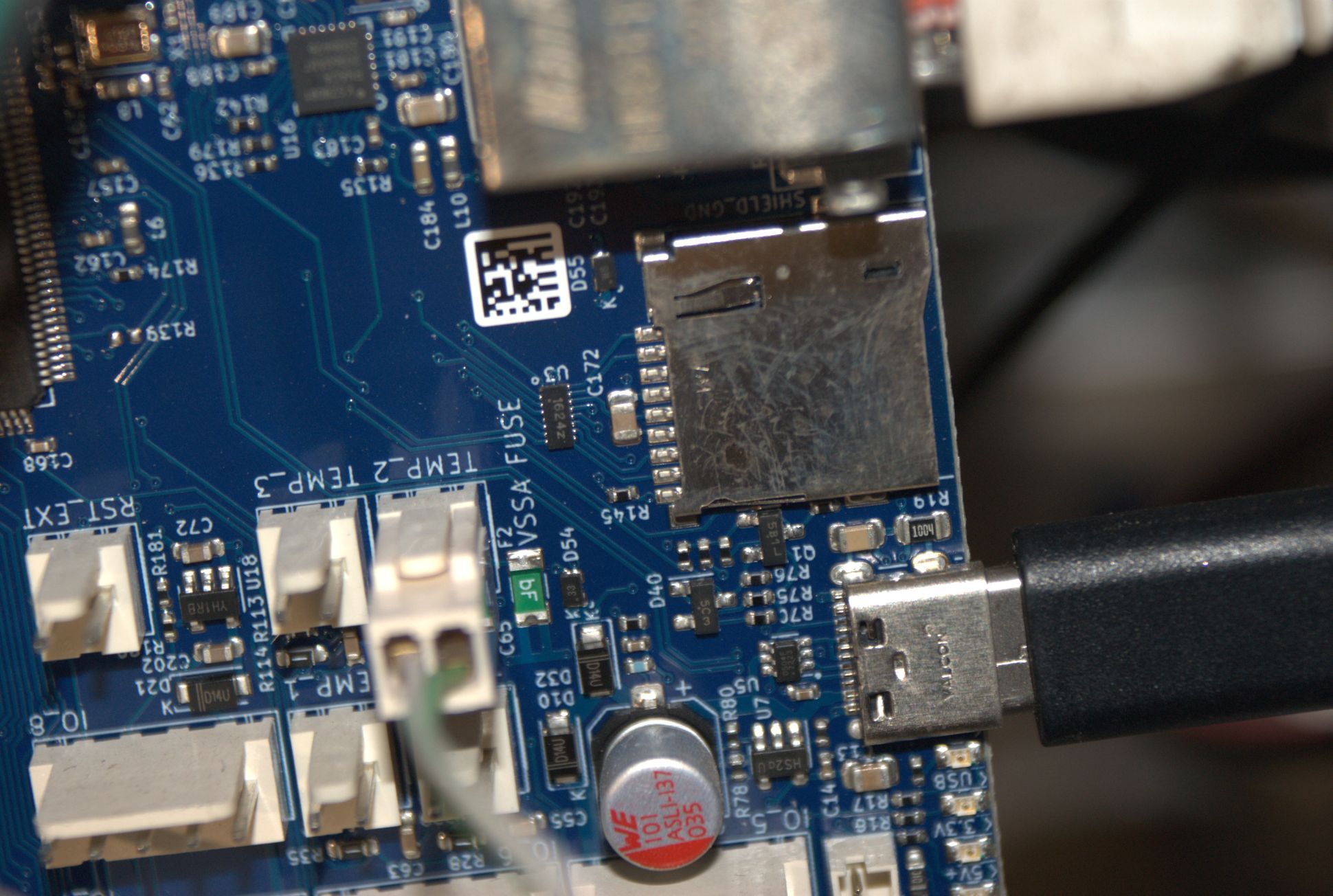
soldering 4
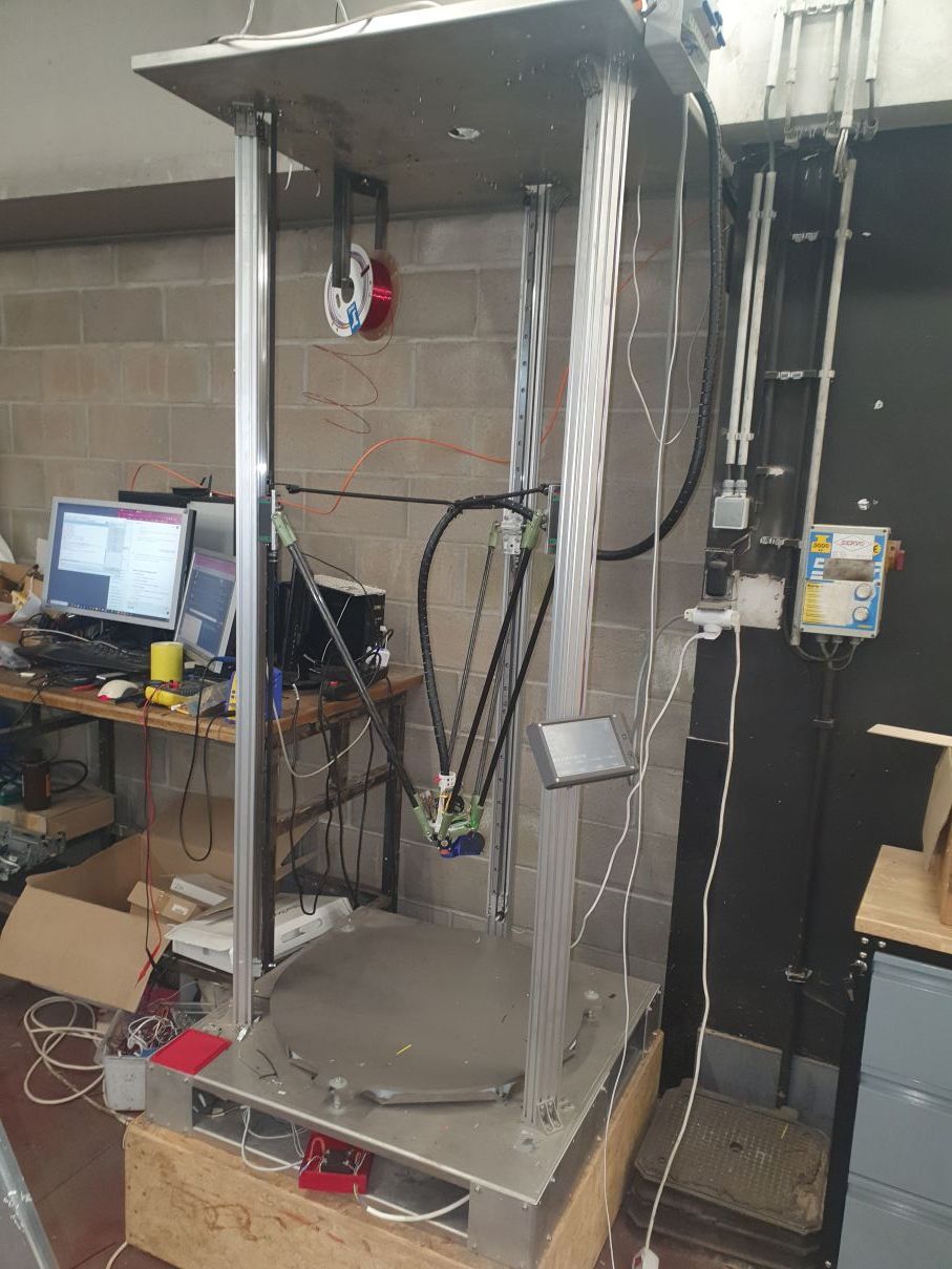
my printerLots of information. Shoot if you have questions.
-
RE: Deleting config.g fileposted in General Discussion
The same problem here. I have a 6xd board. And very regularly the system deletes my config file. It happens always after an emergency stop in the web interface.
Now i used for the first time the STOP button in the paneldue. After this STOP i rebooted and the duet is not connecting with the web anymore. In the paneldue i got a startup but without configfile. So no connection with the webinterface and no homing, so no printing. When the SD-card was checked in Windows. the SD-card was not readable anymore in windows and after complete format as ex-plained in the duet documentation it is ok for windows but stil not readable according to duet. (No errors with windows check and the files are there in Windows)
So now i can start up my delta. i get a screen in paneldue. it can't find the sdcard and i get no internetconnection anymore. So, i suppose it is starting up from eprom but is not reading anything from the sd-card file.Using all the newest firmware for as well the board as the webinterface
Any idea?
-
RE: tool view in Duet webcontrol heater shows wrong temperatureposted in Duet Hardware and wiring
@droftarts Thanks that worked, but i had to do it manually, doesn't seem to work with the rrf configurator. I take it up with @chrishamm
-
tool view in Duet webcontrol heater shows wrong temperatureposted in Duet Hardware and wiring
Hi,
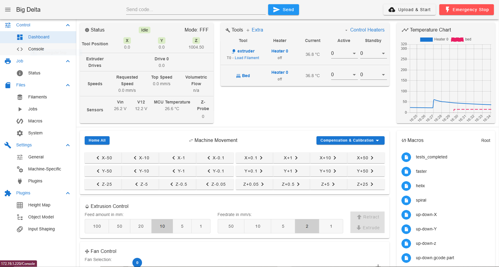
Duet Web Control 3.5.2 shows the extruder temp for as wel my extruder as my bed temperature. Although in the graph you can see the temperatures are different.
I in cluded as wel my configfile as my webview. I creeated my config via the rrf config tool. Any ideas. ?
; Configuration file for RepRapFirmware on Duet 3 Main Board 6XD ; executed by the firmware on start-up ; ; generated by RepRapFirmware Configuration Tool v3.5.5 on Fri Nov 15 2024 17:03:42 GMT+0100 (Central European Standard Time) ; General G90 ; absolute coordinates M83 ; relative extruder moves M550 P"Big Delta" ; set hostname ; Accessories M575 P1 S0 B57600 ; configure PanelDue support ; Network M552 P172.19.1.220 S1 ; configure Ethernet adapter M553 P255.255.255.0 ; set netmask M554 P172.19.1.1 ; set gateway M586 P0 S1 ; configure HTTP ; Accelerometers M955 P0 C"spi.cs4+spi.cs3" I20 ; configure accelerometer on board #0 ; Motor Idle Current Reduction M906 I30 ; set motor current idle factor M84 S30 ; set motor current idle timeout ; External Drivers M569 P0.0 S1 R0 T5:5:10:0 ; driver 0.0 goes forwards and requires an active-low enable signal (X axis) M569 P0.1 S1 R0 T5:5:10:0 ; driver 0.1 goes forwards and requires an active-low enable signal (Y axis) M569 P0.2 S1 R0 T5:5:10:0 ; driver 0.2 goes forwards and requires an active-low enable signal (Z axis) M569 P0.5 S1 R0 T5:5:10:0 ; driver 0.5 goes forwards and requires an active-low enable signal (extruder 0) ; Axes M584 X0.0 Y0.1 Z0.2 ; set axis mapping M350 X1 Y1 Z1 I0 ; configure microstepping without interpolation M92 X426.67 Y426.67 Z426.67 ; configure steps per mm M566 X1200 Y1200 Z1200 ; set maximum instantaneous speed changes (mm/min) M203 X18000 Y18000 Z18000 ; set maximum speeds (mm/min) M201 X1000 Y1000 Z1000 ; set accelerations (mm/s^2) ; Extruders M584 E0.5 ; set extruder mapping M350 E16 I0 ; configure microstepping without interpolation M92 E663 ; configure steps per mm M566 E1200 ; set maximum instantaneous speed changes (mm/min) M203 E3600 ; set maximum speeds (mm/min) M201 E1000 ; set accelerations (mm/s^2) ; Kinematics M665 L723 R350 B250 H1004.5 ; set delta radius, diagonal rod length, printable radius and homed height M208 Z0 S1 ; set minimum Z M666 X0 Y0 Z0 A0 B0 ; endstop adjustments and XY tilt, can be determined using auto calibration as well ; Probes M558 K0 P8 C"io1.in+io1.out" H5 F1200 T6000 ; configure unfiltered digital probe via slot #0 M558 H30 ;*** Remove this line after delta calibration has been done and new delta parameters have been saved G31 P500 X0 Y0 Z0.1 ; set Z probe trigger value, offset and trigger height ; Endstops M574 X2 P"io2.in" S1 ; configure X axis endstop M574 Y2 P"io3.in" S1 ; configure Y axis endstop M574 Z2 P"io4.in" S1 ; configure Z axis endstop ; Mesh Bed Compensation M557 R245 S40:40 ; define grid for mesh bed compensation ; Sensors M308 S0 P"spi.cs1" Y"rtd-max31865" M308 S1 P"temp2" Y"thermistor" A"bed" T100000 B4138 ; configure sensor #1 ; Heaters M950 H0 C"out0" T0 ; create heater #0 M143 H0 P0 T0 C0 S320 A0 ; configure heater monitor #0 for heater #0 M307 H0 R2.43 D5.5 E1.35 K0.56 B0 ; configure model of heater #0 ; Heated beds M140 P0 H0 ; configure heated bed #0 ; Fans M950 F0 C"out3" ; create fan #0 M106 P0 C"extruder" S0.3 B0.1 H1 T45 ; configure fan #0 M950 F1 C"out7" ; create fan #1 M106 P1 C"Nozzle" S0 B0.1 H1 T45 ; configure fan #1 ; Tools M563 P0 S"extruder" D0 H0 F0:1 ; create tool #0 M568 P0 R0 S0 ; set initial tool #0 active and standby temperatures to 0C -
RE: Acellerometer via stacked temp daughterboard on 6xdposted in Duet Hardware and wiring
@jay_s_uk thanks. i forwarded it to him.
-
RE: Acellerometer via stacked temp daughterboard on 6xdposted in Duet Hardware and wiring
@dc42 Thanks, solved it. But then should the rrf configuration tool be changed because when you select the 6xd board you can't select the spi.cs4. It gives the spi.cs outputs from the 6HC
-
Acellerometer via stacked temp daughterboard on 6xdposted in Duet Hardware and wiring
Hi,
I am using a fixed acclerometer via a stacked daughterboard on a 6xd duet3d.
I connected 2 tempsensors via rtd1 and rtd2 on the temp daughterboard and the accelerometer as suggested in the duet3d manual. The suggestion is now to configure the accelerometer via
M955 P0 C"spi.cs4+spi.cs3" ; all wires connected to temp DB connector, stacked on temperature daughterboard
Following this logic the temp sensors should be configured like
M308 S0 P"spi.cs1" Y"rtd-max31865"
M308 S1 P"spi.cs2" Y"rtd-max31865"
Only 1 of the temp sensors seems to work.
I want to exclude an error in the configfile before i start to alter the hardwareI thought the spi.cs numbering goes from 0 to 3?
How comes that the accelerometer is using spi.cs4?what should be the right numbering in the configfile for as well the accelero meter as the tempsensors.
-
RE: how to enable out6 on 6xd for M569.7 command for brakeposted in Duet Hardware and wiring
@oliof i don't get the homing error anymore, so i would think it works now. The moment when i move my z-axis 100 up with the command G1 Z100 F300 nothing moves, but the webinterface says now the z-axis is at 100?
Something is completely off, but i have no idea what.
This is my config.g file and my servos are JMC 180 with brakes. If anybody has any idea.; Configuration file for RepRapFirmware on Duet 3 Main Board 6XD ; executed by the firmware on start-up ; ; generated by RepRapFirmware Configuration Tool v3.5.4 on Mon Jul 29 2024 11:58:08 GMT+0200 (Central European Summer Time) ; General G90 ; absolute coordinates M83 ; relative extruder moves M550 P"Big Delta" ; set hostname ; Accessories M575 P1 S0 B57600 ; configure PanelDue support ; Network M552 P0.0.0.0 S1 ; configure Ethernet adapter M586 P0 S1 ; configure HTTP ; Motor Idle Current Reduction M906 I30 ; set motor current idle factor M84 S30 ; set motor current idle timeout ; External Drivers M569 P0.0 S1 R0 T2.5:2.5:6:1 ; driver 0.0 goes forwards and requires an active-low enable signal (X axis) M569 P0.1 S1 R0 T2.5:2.5:6:1 ; driver 0.1 goes forwards and requires an active-low enable signal (Y axis) M569 P0.2 S1 R0 T2.5:2.5:6:1 ; driver 0.2 goes forwards and requires an active-low enable signal (Z axis) M569 P0.3 S1 R0 T2.5:2.5:6:1 ; driver 0.3 goes forwards and requires an active-low enable signal (extruder 0) ; Axes M584 X0.0 Y0.1 Z0.2 ; set axis mapping ;M350 X1 Y1 Z1 I0 ; configure microstepping without interpolation M92 X106.67 Y106.67 Z106.67 ; configure steps per mm M566 X1200 Y1200 Z1200 ; set maximum instantaneous speed changes (mm/min) M203 X18000 Y18000 Z18000 ; set maximum speeds (mm/min) M201 X1000 Y1000 Z1000 ; set accelerations (mm/s^2) ; Extruders M584 E0.3 ; set extruder mapping M350 E16 I0 ; configure microstepping without interpolation M92 E663 ; configure steps per mm M566 E1200 ; set maximum instantaneous speed changes (mm/min) M203 E3600 ; set maximum speeds (mm/min) M201 E1000 ; set accelerations (mm/s^2) ; Kinematics M665 L723 R350 B275 H1000 ; set delta radius, diagonal rod length, printable radius and homed height M208 Z0 S1 ; set minimum Z M666 X0 Y0 Z0 A0 B0 ; endstop adjustments and XY tilt, can be determined using auto calibration as well ; Probes M558 K0 P8 C"io1.in" H5 F120 T6000 ; configure unfiltered digital probe via slot #0 M558 H50 ;*** Remove this line after delta calibration has been done and new delta parameters have been saved G31 P500 X0 Y0 Z0.7 ; set Z probe trigger value, offset and trigger height ; --- Begin brake control configuration --- ; Define output pin for brake control using logical pin 2 ; M950 P2 C"out6" ; Define logical pin 2 as the output pin connected to out6 ; Assign the brake control to the servo driver M569.7 P0.0 R1 C"out6" ; Assign logical pin 2 (out6) to the brake control of servo driver P0.0 ; Initial brake state ; M42 P2 S0 ; Ensure the brake is initially disengaged ; --- End brake control configuration --- ; Endstops M574 X2 P"io2.in" S1 ; configure X axis endstop M574 Y2 P"io3.in" S1 ; configure Y axis endstop M574 Z2 P"io4.in" S1 ; configure Z axis endstop ; Sensors M308 S0 P"temp0" Y"thermistor" A"Heated Bed" T100000 B4725 C7.06e-8 ; configure sensor #0 M308 S1 P"temp1" Y"thermistor" A"Nozzle" T100000 B4725 C7.06e-8 ; configure sensor #1 ; Heaters M950 H0 C"out0" T0 ; create heater #0 M143 H0 P0 T0 C0 S140 A0 ; configure heater monitor #0 for heater #0 M307 H0 R2.43 D5.5 E1.35 K0.56 B1 ; configure model of heater #0 M950 H1 C"out1" T1 ; create heater #1 M143 H1 P0 T1 C0 S285 A0 ; configure heater monitor #0 for heater #1 M307 H1 R2.43 D5.5 E1.35 K0.56 B0 ; configure model of heater #1 ; Heated beds M140 P0 H0 ; configure heated bed #0 ; Fans M950 F0 C"out3" ; create fan #0 M106 P0 S0 L0 X1 B0.1 ; configure fan #0 M950 F1 C"out4" ; create fan #1 M106 P1 S0 B0.1 H1 T45 ; configure fan #1 ; Tools M563 P0 D0 H1 F0 ; create tool #0 M568 P0 R0 S0 ; set initial tool #0 active and standby temperatures to 0C ; Fake homing of all axes G90 G92 X0 Y0 Z0 ; Set the current position to X=0, Y=0, Z=0