Duet3D Logo Duet3D
    • Tags
    • Documentation
    • Order
    • Register
    • Login
    1. Home
    2. LeonMF
    3. Posts
    • Profile
    • Following 0
    • Followers 0
    • Topics 18
    • Posts 117
    • Best 6
    • Controversial 0
    • Groups 0

    Posts made by LeonMF

    • RE: Weird extrusion issue

      @oliof said in Weird extrusion issue:

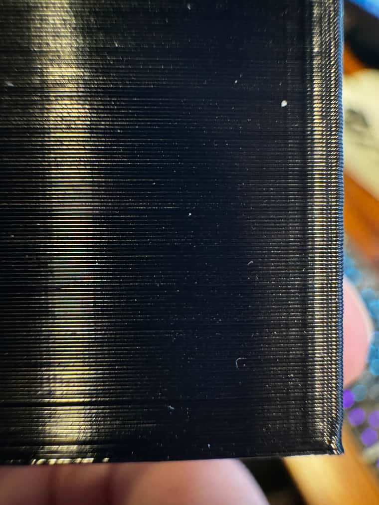
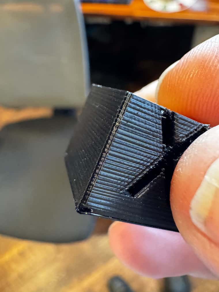
      @LeonMF These artefacts look like Bang-Bang induced bed displacement artefacts. I guess you are using an SSR with an AC bed. If its not a zero crossing SSR, get a better SSR, and try to reduce the SSR frequency (I had luck with 1Hz in the past, but it depends on your SSR).

      I'm embarrassed to admit that I defaulted to bang-bang after my last printer caused problems. I never considered it an issue as I wasn't aware that bed stability of a degree or two would be that much of a big deal. I PID tuned this printer and do not have flickering lights. It also seems to have solved my problems.

      Ignore the first layer, I was a bit far away.
      IMG_0529.jpg

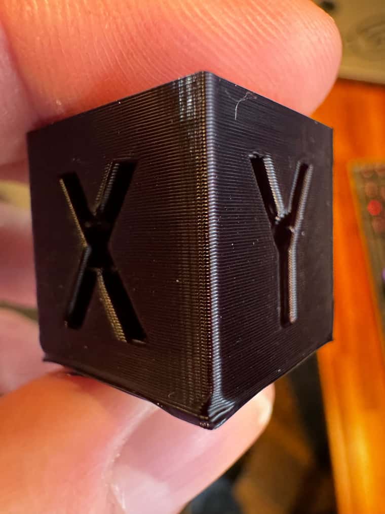
      I have more testing to do but the preliminary results here look good.

      Thank you!

      posted in Tuning and tweaking
      LeonMFundefined
      LeonMF
    • RE: Weird extrusion issue

      @droftarts said in Weird extrusion issue:

      @LeonMF In the first image, the wobble on the edge is very consistent, and has a period of 10 layers. What was the layer height, and what is the pitch of your leadscrews? I'd guess that one is a problem with the stepping distance of the Z motors, and you should try and use layer heights that are whole numbers of Z motor steps. Hopefully the Z leadscrews are metric, not inch!

      The second one is also quite consistent (when you zoom in on the picture), and looks to have 7 or 8 layers in each period. What layer height was that done at?

      Maybe post your config.g for good measure.

      Ian

      The leadscrews are T8x2 leasdcrews with POM antibacklash nuts. I don't have the config.g here with me at work but I'm running 0.2 layer heights, which is an integer multiple of steps.

      One thing I need to do is some testing with different sized models and see what the impact is. I've not been deliberate about that but it should highlight the extrusion considerations vs z-wobble.

      posted in Tuning and tweaking
      LeonMFundefined
      LeonMF
    • RE: Weird extrusion issue

      @oliof said in Weird extrusion issue:

      just to get the obvious out of the way: Did you PID tune your bed?

      I'm using Bang-bang because I've had problems with flickering lights in the past with PID. I'm open to trying it if there's a chance it could do something.

      posted in Tuning and tweaking
      LeonMFundefined
      LeonMF
    • RE: Weird extrusion issue

      @mrehorstdmd said in Weird extrusion issue:

      @LeonMF It looks like both the extruders you mentioned are dual drive type.
      Have you seen this: https://youtu.be/32dTLRNIYmw?si=d5yZB3FCSG-k59EY ?

      I'm at work so can't watch the video in detail but there's a good chance it's related to this. I'm not sure there's much I can do about it given the closed nature of the E3D components.

      posted in Tuning and tweaking
      LeonMFundefined
      LeonMF
    • Weird extrusion issue

      I've been chasing a weird issue for awhile now... actually, probably since I built my Railcore 2 right after the Duet 3 was released.

      Setup:

      • Railcore II ZLT
      • Duet 3 w/SBC
      • Revo Roto w/ toolboard and custom aluminum mount

      Previously, I had a Hemera and then converted that to a Hemera Revo.

      I've completely rebuilt the Z axis system with better Z rods, kinematic bed mount, and oldham couplers, and I'm 99.43% positive that the Z axis is not my issue.

      My next stop is to reach out to E3D if nobody here knows what's going on!

      The problem has existed across two different extruders (Hemera and Revo Roto) and both direct and CAN toolboard based extruder drivers! The actual steps/mm at 16x microstepping is 90% of factory for the Revo Roto (2414 actual vs 2682 factory). When I was running the Hemera, the published 381 vs 409 steps/mm was about 93% (though I could have been calibrated to PLA at 1.0 extrusion explaining the difference).

      I know that various factors affect extrusion flow rate for different materials but that's usually small single digit percentages. For the most part, this is all fine, i just calibrated the extrusion to match what I'm seeing but there appears to be a very, very, very subtle extrusion change every few layers where it under extrudes an almost imperceptible bit and it is driving me mad. Nothing I do changes the result unless I dramatically underextrude. I've even tried changing the stepper mode based on the youtube video from Thomas Sanlanderer.

      I suspect the difference between published and actual steps/mm is the key here but it doesn't make sense and I'm at a loss!

      As you can see, part size/geometry does seem to have an impact. The second photo looks much, much worse than it actually is. I photographed it for maximum impact but you can barely see or feel the ridges in real life.

      Any help, including being told to "go talk to E3D" is welcome! Thanks!

      IMG_0301.jpg
      IMG_0524.jpg

      posted in Tuning and tweaking
      LeonMFundefined
      LeonMF
    • RE: Magnetic Filaments Sensor with toolboard - No Data

      @phaedrux I take that back. I'm still getting no data received.

      (Deleted M122 results)

      False alarm. My ground wire pin wasn't seated in the Molex connector on the sensor side and, apparently, worked long enough for me to prepare for a print.

      posted in Filament Monitor
      LeonMFundefined
      LeonMF
    • RE: Magnetic Filaments Sensor with toolboard - No Data

      @phaedrux I finally had a chance to get back to this and my problem was that the signal and voltage wires were shorted. Those tool board connectors are too darned small!

      Thanks for the help!

      posted in Filament Monitor
      LeonMFundefined
      LeonMF
    • RE: Magnetic Filaments Sensor with toolboard - No Data

      @phaedrux I'm 99.9% certain the wire is OK. I used silicone wires for this and they insulation is made of butter. The internal wire isn't exposed, though.

      Would I be wrong in assuming that the sensor would not blink red/green if it isn't communicating through that yellow wire?

      posted in Filament Monitor
      LeonMFundefined
      LeonMF
    • Magnetic Filaments Sensor with toolboard - No Data

      I have a magnetic filament sensor which, TBH, I really haven't been using because even though it's mounted an inch above my Hemera and usually reports 90s% to 100s%, it would always fail out on prints with small movements.

      I've upgraded my printer to 3.4, fixed my steps/mm on the extruder, and am hopeful that it will work reliably now.

      Recent print result from directly connected to Duet:

      Duet3D rotating magnet filament monitor v3 on pin (io2.in,i2c0.clk), enabled, sensitivity 26.14mm/rev, allow 5% to 250%, check printing moves every 3.0mm, version 3, mag 128 agc 93, measured sensitivity 26.22mm/rev, min 97% max 104% over 1106.5mm
      

      I just installed a toolboard and have everything working except that the sensor returns "No Data Received". I get blinking green red when not moving and blinking green when moving but no data.

      Toolboard filament monitor config line. Note the wide monitoring range because I don't trust a tight range... if I could get this working.

      M591 D0 P3 C"121.io1.in" S0 R5:200 L24.6 E3.0 A0
      

      I've quadruple checked my wiring for connections. The pins appear to be secure and well connected and I would presume the red/green flashing wouldn't happen if communication wasn't occurring??

      IMG_3086.jpg

      I'd love to get my umbilical between the printer and print head down to just power and CAN but this is blocking me from making that transition. Am I doing something dumb?

      posted in Filament Monitor
      LeonMFundefined
      LeonMF
    • RE: Cura & Duet 3 relative extrusion issue

      @dc42 The information that the macros revert to previous mode was key.

      I just added an extra M83 in my slicer start script after my macro call and removed all the superfluous M83s that I had added to the startcode. That does mean an M83 followed by an M83 but it seems to work.

      If you need I can do some extra testing but, for now I seem to be working fine.

      Thanks!

      posted in General Discussion
      LeonMFundefined
      LeonMF
    • RE: Cura & Duet 3 relative extrusion issue

      This person had the same problem I do but I'm unclear what the resolution to their problem was:

      https://forum.duet3d.com/topic/22464/m83-problem/4

      posted in General Discussion
      LeonMFundefined
      LeonMF
    • Cura & Duet 3 relative extrusion issue

      OK, I tried searching and didn't see anyone else having this problem.

      I have a Duet 3 (MB6HC) w/SBC running version 3.3.

      When I slice in Cura 4.12.1 in relative extrusion mode, it sets the extrusion to absolute (this is by design), does the startup code, then sets it back to relative. Theoretically, this should be fine. Especially since I set M83 immediately in my startup script (and twice more for good measure). Sometimes this works and prints fine, sometimes the system never exits absolute mode and the printer doesn't extrude anything because all the extruder movements are relative. However, commenting out the M82 line in the gcode file makes everything work fine.

      The code from the slicer that doesn't work

      T0
      M190 S80
      M104 S245
      M109 S245
      M82 ;absolute extrusion mode
      M98 P"Cura_Startcode.g"
      M83 ;relative extrusion mode
      G1 F1500 E-1
      ;LAYER_COUNT:36
      

      my Cura_Startcode.g

      M83 ;Need to set relative extrusion mode. Override Cura set to absolute.
      G1 X0.0 Y0.0 Z1.0 F2000.0 ; prepare to prime
      G92 E0 ; reset extrusion distance
      G1 Z0.2 F1000.0
      G1 X60.0 E9.0  F1000.0 ; priming
      G1 X125.0 E12.5  F1000.0 ; priming
      G1 Z0.5 F1000.0
      M83
      G92 E0 ; reset extrusion distance
      M83
      

      Just commenting out line 5 in the first code block above seems to make everything work fine.

      Am I doing something dumb or have I found some obscure bug?

      posted in General Discussion
      LeonMFundefined
      LeonMF
    • RE: Independent Z with Independent Sensors U steps/mm wrong

      Defining U in config.g before then combining worked for me. Thanks for the help!

      posted in Duet Hardware and wiring
      LeonMFundefined
      LeonMF
    • RE: Independent Z with Independent Sensors U steps/mm wrong

      @phaedrux There's no reason to treat this like a Promega. I've gutted it, changed the Z drive system to dual lead screws, the rails, the carriage, the board, the bed...

      posted in Duet Hardware and wiring
      LeonMFundefined
      LeonMF
    • RE: Independent Z with Independent Sensors U steps/mm wrong

      @dc42 @Phaedrux OK, I can certainly modify my config to create the U axis and then combine them. The posted wiki page doesn't say to do that so I missed the obvious!

      posted in Duet Hardware and wiring
      LeonMFundefined
      LeonMF
    • RE: Independent Z with Independent Sensors U steps/mm wrong

      @phaedrux said in Independent Z with Independent Sensors U steps/mm wrong:

      https://duet3d.dozuki.com/Wiki/Bed_levelling_using_multiple_independent_Z_motors

      Yes, that's what I based my config on!

      posted in Duet Hardware and wiring
      LeonMFundefined
      LeonMF
    • RE: Independent Z with Independent Sensors U steps/mm wrong

      Here is a dropbox link to my config:
      https://www.dropbox.com/s/a6954n6rumxr327/MonkeyMega-Config-2019-09-07.zip?dl=0

      posted in Duet Hardware and wiring
      LeonMFundefined
      LeonMF
    • Independent Z with Independent Sensors U steps/mm wrong

      A whole bunch of months ago, I retrofitted my Promega to have dual Z lead screws with independent sensors for homing. Then I had so many issues with the Maestro board skipping steps, the extruder system behaving badly, and a work trip that kept me busy for several months.

      I'm back to it now, I've redesigned the X carriage, swapped in a Duet WiFi that I had lying around while waiting for the Duet 3 and I've got everything pretty much back to working but the Z homing is behaving weird.

      I set the U axis at the same steps/mm as Z but in the commented out line the U axis gets 837.20steps/mm and E0 gets 420. When use the second option where I try to set U to 400 after the fact, I get U and E as 420.

      0_1567892652110_26a0d602-dec6-4152-a956-f1fa777a92b6-image.png

      0_1567892694330_7201cac4-dc66-49dd-9cbf-316f02ae91fa-image.png
      [0_1567892760893_MonkeyMega-Config-2019-09-07.zip](Uploading 100%)

      I'm on firmware 2.03 and, at this point, I'm at a complete loss as to what to do. I can try putting some overrides in the homez file but I'd rather find out if I'm doing something wrong first!

      posted in Duet Hardware and wiring
      LeonMFundefined
      LeonMF