Duet3D Logo Duet3D
    • Tags
    • Documentation
    • Order
    • Register
    • Login
    1. Home
    2. lord binky
    3. Best
    • Profile
    • Following 0
    • Followers 0
    • Topics 10
    • Posts 83
    • Best 21
    • Controversial 0
    • Groups 0

    Best posts made by lord binky

    • RE: I see no effect of microstepping on torque

      @e4d yeah.... it's not the total torque that changes, it's the torque per step. So simplified you got two coils and we are looking at two teeth on the rotor. Coil A is at full current so it's pulling the full torque into that position on tooth A which is a full step position. A half step will put half current on each coil so you only have half the torque pulling into the middle of the two teeth. Continue to put full current on coil B, and zero on coil A and you get full torque to move you from the mid position between Teeth A and B to the full step position of B.

      Whether you microstep or not you go through full current on a coil in the full step positions so your total torque is the same over a distance, but how well you constantly and repetively hit a microstep outside that full step position decreases as you increase the number of positions between full steps. TLDR; the tiny changes in current may not actually move you that tiny amount between the teeth, but when it comes to the tooth being fully lined up it's all the same.

      posted in Using Duet Controllers
      lord binkyundefined
      lord binky
    • Fixed my high pitched fan (electrical) noise

      So I have a super annoying high pitch whine on a pair of Sunon 12v fans (MF25101V1) in a push/pull on a mosquito clone. While I'm replacing the hot-end heater I figure it should be an easy thing to either fix or identify why my fans have this high pitched induction coil whine that slowly claws at your soul. Might as well fix while things are torn down... and into the rabbit hole i dove. Threw my scope on it since I felt like it was some electrical noise was carrying through to the fan motors. Of course I did, I'm using switched mode supplies. Regular 12v rail had all kinds of electrical noise at 500Hz, 1kHz, and 100kHz.

      Well, somethings causing it right? Let's start with filtering some culprits out. I try a capacitor to filter it... nothing. Ok well, a temporary voltage offset on the noise but the waveform didn't change at all? Fine...grab a toroid and do a simple choke...scream.. multiple LC filters ...and still no response...Am I a ghost now? WTF is this sorcery?!

      So eventually I snip a fan out and blissful silent air flow... So it turns out that the issue was running two fans off the same cable right up to their own leads... Noise is gone soon as each fan gets it's own wires back to the terminal strip (they're wired always on).

      I'm just happy the noise is gone and won't question why I've never had an issue wiring this way before. Still I thought I'd share in case someone has a whine / high pitched noise they can't get rid of, then here's one possibility.

      TLDR; Parallel DC Fans sharing a power cable can cause high pitched feedback sometimes, intermittently, and in just the right way to test your sanity.

      posted in Duet Hardware and wiring
      lord binkyundefined
      lord binky
    • Sharing my Delta bed.g spreadsheet

      Here's the three versions I when changing my bed.g for my delta printer. They use 32 points and it generates a column that I can cut and paste into my bed.g It works for me, my calibration runs in the 0.01 mm range. Feel free to make a copy and do whatever you want with it, I'm just sharing in hopes of it being helpful to someone. Please watch the printer carefully until you're confident it's working for you, while it works for me I'm just throwing it out there to help and don't make any claims to it working flawlessly although I can't see how it'd go bad if you use values reasonable to your machine.

      Variables to change are:
      -bed size (the outer ring of probe points)
      -Calibration Factor
      -Oversize factor (only on the oversized one where I use it to dial in my arm lengths)

      The first one is my default arrangement
      12 points at the bed size distance (perimeter), 12 more at 2/3 the bed size distance, 7-points at 1/3 and one for the center.
      https://docs.google.com/spreadsheets/d/1trfFyw2LqvRUeq3WPKtEaKaRGZOVwk4034zErVPo3jE/edit?usp=sharing

      The second arrangement I get better calibration numbers from
      16 points at the perimeter, 12 inside (2/3 distance), and 3 points (1/3 distance) and a center point
      https://docs.google.com/spreadsheets/d/17S-CsZrUSqeNFooCKBznFLhmKTVUeivGca3umMWm86s/edit?usp=sharing

      The third is what I use to test / calibrate my arm length. I calculate the oversize factor as the distance to just inside the maximum bed radius over the bed size parameter that I can test within the limits of the towers. Please be careful and watch closely if you use this one.

      https://docs.google.com/spreadsheets/d/172jtcU9UQyQi1yUPvm9tagQ7Fl1T8Yxcv_s8HN2PATI/edit?usp=sharing

      I will try to update if there is a major flaw, otherwise please treat it as a starting point for you play with generating your own test points.

      posted in Tuning and tweaking
      lord binkyundefined
      lord binky
    • RE: Best Choice of Motor for a Delta Printer

      @ignacmc

      Ok, here's some pics. The first is an example of the setup. The others show thickness, the needle bearing you have options depending on the surface of the motor face, the ball bearing set while the ID being the same as the motor shaft is nice i prefer the needle bearings for contact area against the pulley.

      20220425_190447.jpg

      20220425_190319.jpg

      20220425_190034.jpg

      20220425_190142.jpg

      posted in Duet Hardware and wiring
      lord binkyundefined
      lord binky
    • RE: Inductive Z Probe Settings

      depending on the repeatability you want, you may want to slow the feedrate which is really because of the worst part of inductive probes. Most inductive probes switch at 500hz until you you break the ~$60 retail price point for industrial sensor to get 1khz to 3 khz ( next price point is like ~$150+ and specs can get to 5khz). So the faster you're probing the larger the distance variation between trigger intervals. i use a ie5390 i grabbed off of ebay for like $30 and it operates at 1khz and i go with 60mm\min to get .003mm repeatability which is only a microstep and it levels (delta printer) to .01mm over a 300mm probe area

      posted in Tuning and tweaking
      lord binkyundefined
      lord binky
    • Extruder cable shielding improved surface finish (slightly).

      Long story short, all three axis stepper motor cables are shielded (EMI mesh sleeve) on my delta printer (although this could apply to any style) so I skipped doing it on the extruder. Half-assing it bit me again and it may be what got rid of the irregular surface ripple that kind of looked like a salmon skin/moire pattern that you only really see when the surface is glossy. Yeah, that really fine one that drives some of us crazier than massive ghosting does. Until this point I had no indication my electronics had any glaring issues and wrote it off thinking I had that well in hand. I just glared at the delta my mechanics blaming them as the source leaving me completely stumped for what the real cause was though. Anything that seemed a plausible mechanical source I reached out to fix hoping it would be the thing to remove those tiny artifacts even though it didn't match up with anything obvious math wise.*

      I discovered this while I was playing with the new input shaping plug-in. My hotend fans are normally always on and I unplugged them while using the accelerometer to decrease the noise level on it. Then while toying with the plug-in I heard extruder noise that was almost a whine that I couldn't hear over the hotend fans. I noticed it while homing and then dead quite after homing was done made it stand out though. So I homed again and reached over to feel the motor, and it's vibrating with some oscillation when the axis motors are going. I just sat for a minute with my face in my hand and wishing I could give past-me a slap to the back of the head for stopping 3/4 of the way through on shielding the motor cables. I wanted to share my success on this in case it can help anyone else frustrated with calming the waves in the specular reflections even if it is also a facepalm moment of shame.

      *- That isn't to say there aren't other things causing it in another build. I just have happened to already done my best to mitigate them in previous rabbit holes on belts, pulleys, eccentricities on anything round and rotating, arm lengths, arm joints, arm spacing, then arm rigidity, all the extruder bits, fan vibration, frame vibration, bearings (both the linear slides and stepper motor bearings), chasing this stupid pattern.

      posted in Tuning and tweaking
      lord binkyundefined
      lord binky
    • RE: Choosing correct motor for Delta

      @Danal I use the same Motors on my Rostock max for years now and they've held up quite well for the abuse I did on them. I have looked for lower inductance / inertia 0.9 steppers with good torque but I haven't found one I'm confident will perform better for a decent price (I'm looking at you moons' industries...)

      If you get a chance, test out my settings I scope tuned for the motors. Mine run 1500ma without getting hot and are as silent as I can expect of them.

      https://forum.duet3d.com/topic/13028/my-tuned-tmc2660-settings/2

      posted in Duet Hardware and wiring
      lord binkyundefined
      lord binky
    • RE: 3 spehre/point Delta ("Spiderbot")?

      You can get the mathematical differences with one of the calculators ( i like the openscad simulator). The optimal arm spacing is dependent on your print diameter, but you also have a trade off with printable area since you'll have to move the balls further from the center of the effector. Since you can't really go further than having the joints be over lapping, that's kind of the concept to ride that optimal point at least math wise. As for how it works out in practice, not clue but there's so many little variables in the whole system that I don't see it helping that much when there's enough knowledge about the normal configuration you can easily tease out what is probably off when your troubleshooting.

      posted in 3D Printing General Chat
      lord binkyundefined
      lord binky
    • My tuned tmc2660 settings

      Following the trinamic tmc2660 manual and spreadcycle guide I busted out my o-scope with a current probe and a helping hands on the sense resistor. The motors I tuned were Wantai 42BYGHM809 and a PG35L-048. I run a delta, and my steppers are running at 1.5 out of the specced 1.7A and they are staying significantly cooler than when I tuned by ear and they are behaving much better for me, it even got my past the .02 bed leveling barrier I was at.

      Anyways, thought I'd share my efforts in case it might help someone.

      Wantai 42BYGHM809
      M569 P0 D2 F2 B2 Y01:09:02

      PG35L-048
      M569 P3 D2 F3 B3 Y03:07:02

      posted in Tuning and tweaking 42byghm809
      lord binkyundefined
      lord binky
    • RE: Question: Recommendation for mechanical endstops

      I prefer the contactless approach and just wire in (directly with no extras has worked fine for me) A3144 digital hall effect sensors (~$1 ea.) for my endstops and slap a magnet on the moving part. You can home fast and do a slow back and return and the repeatability has been hands down better over time than contact switches I've tried.

      posted in Duet Hardware and wiring
      lord binkyundefined
      lord binky
    • RE: What can I do against the moire effect?

      I finally cleared this up on my E3d titan, had moire patterns like the second picture first post. I eliminated the software/ electronics ( changed stepper driver settings, each value individually although it was on the fly during 10mm test towers, and even purposely bad ones), motor current, microstepping high and low, thegolden ratio layer heights, extrusion/flow rate,slicers, motor cables. It confirmed what I suspected in my case which was that it was hardware and top of the list was the titan itself.

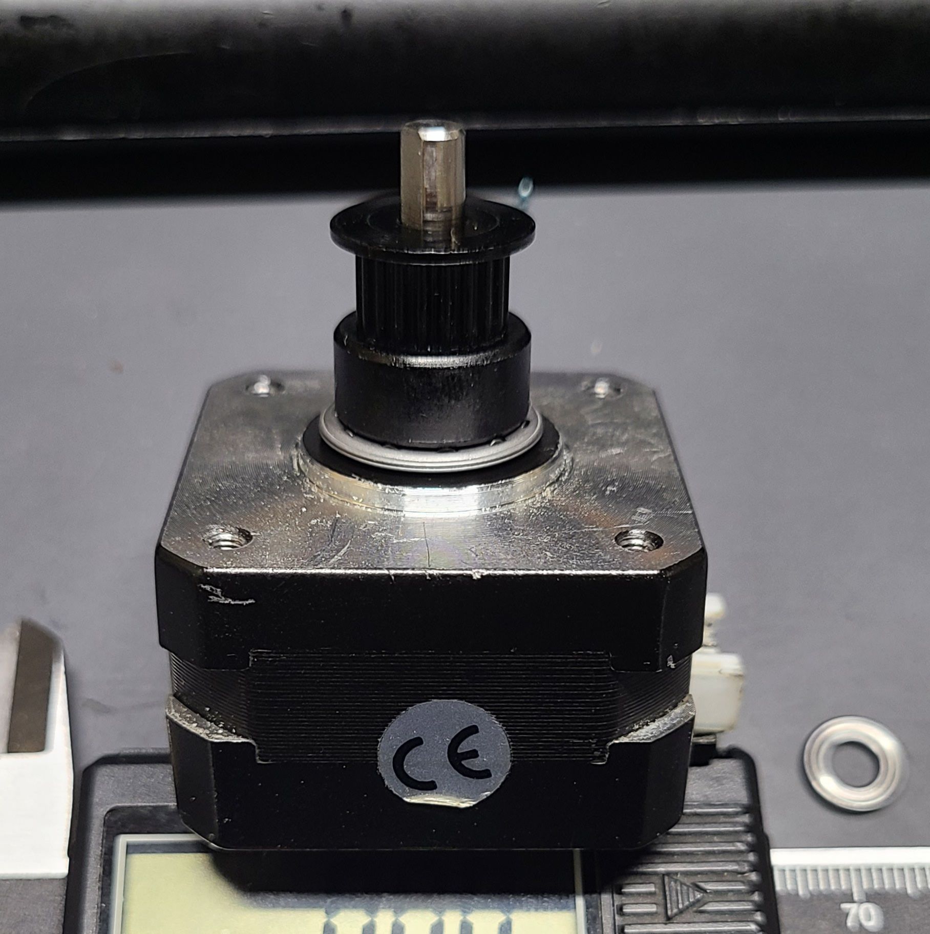
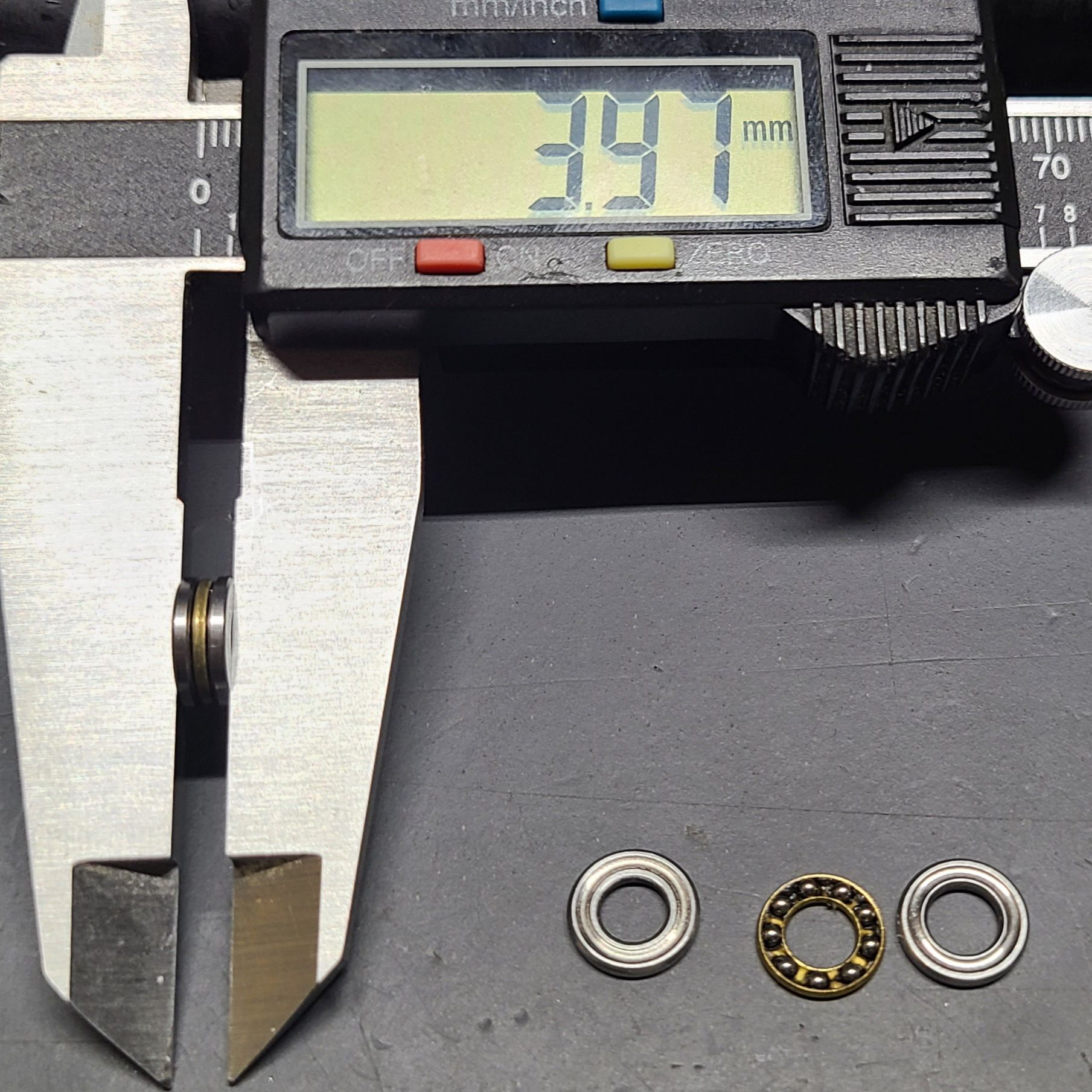
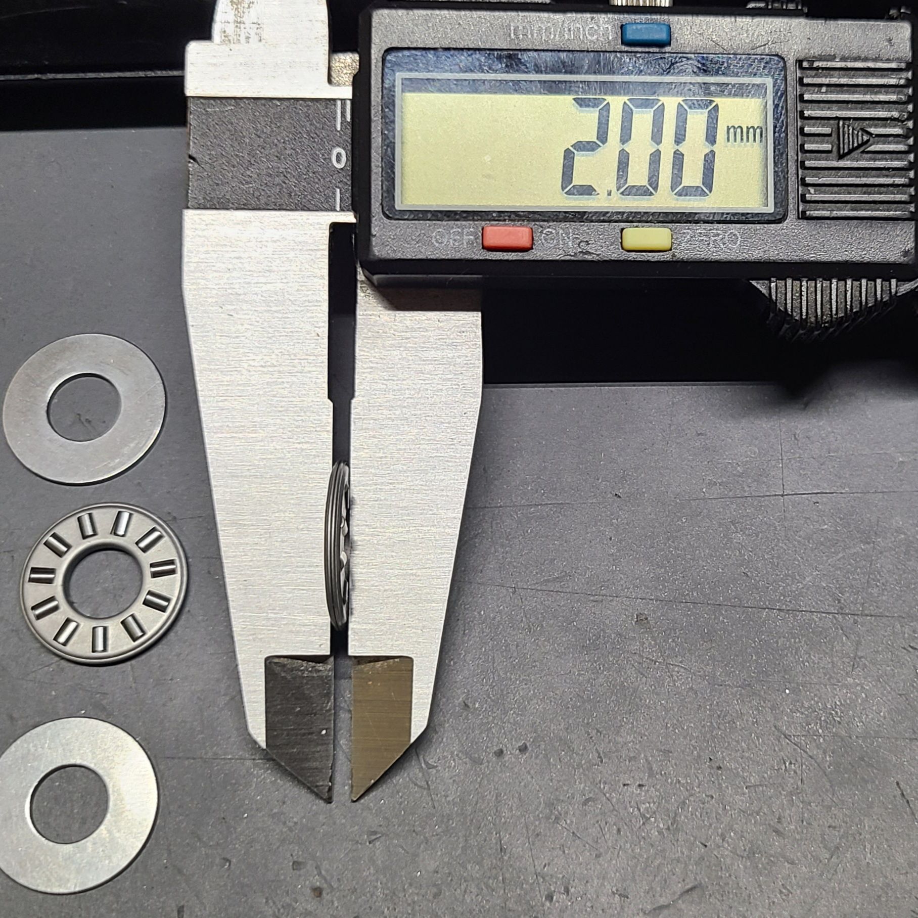
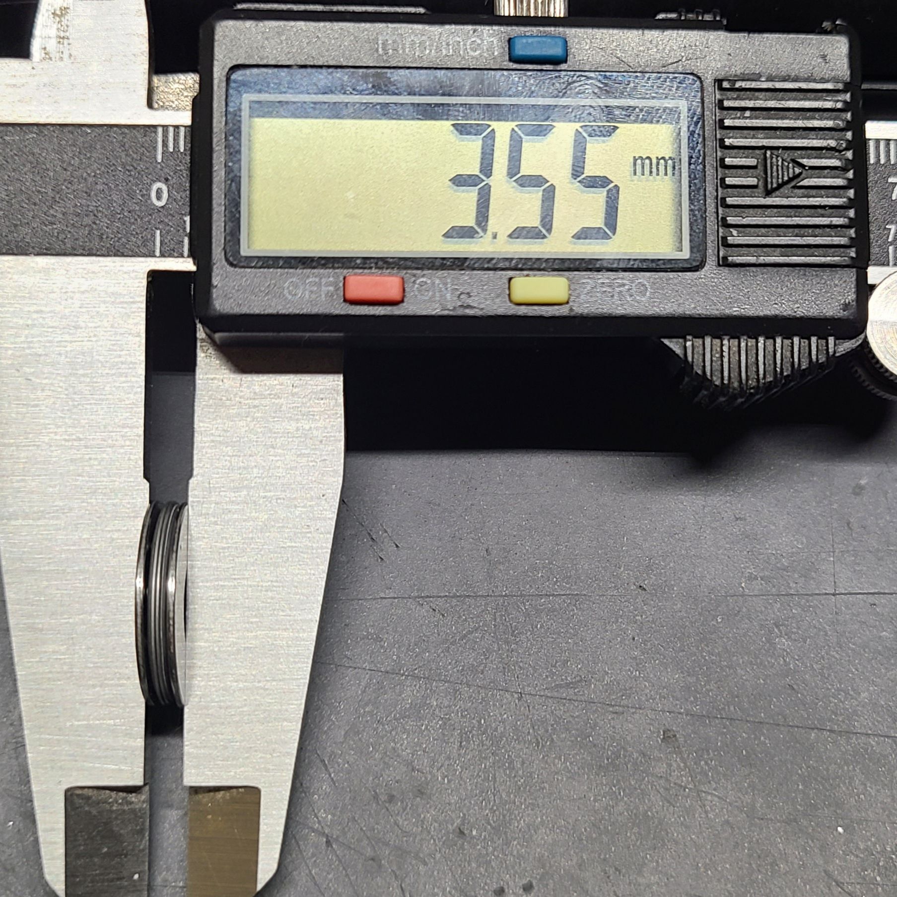
      I don’t know what fixed it specifically since at that point I wasn’t doing that many disassemblies. I reprinted the motor mount and sanded to try to keep things perpendicular. I drilled out the the old titan cover plate and added a copper sleeve to the motor shaft intending to constrain shift alignment and any deflection from the tensioner. I had lots of spare parts since I swapped everything on the titan but the main body. When arranging the gears, I adjusted the delrin gear on the hobb so the tensioner arm was as close to perfect feeding filament into the center of the hobb. When I was doing that I noticed the both delrin gears had slight issues, one didn't sit perpendicular on the hobb when looked at with an engineer square ( I used it a on anything I could to see who my culprits could be for not being perpendicular when they should) and the other was not truly flat when viewed against the straight edge. Fixed one up and put it in and noticed when I was trying to get the gears flush to a razors edge (literally) that the hobb gear wobbles weird in it's bearing. So I swapped out the hobb's bearing in the body of the titan, (the one in the cover was checked too). I also added so kapton tape where the v6 mounts into so there is zero play even with effort. I finished putting it back together and one or a combination of things fixed it. Going to a hemera was my next move if I didn't get rid of it here, if only for the on motor mount points for my probe and and flex filament performance.

      My gut says based on the pattern, it was likely the fact that the gears were not perfectly in line (seriously, I couldn't tell other than the bearing until I got out my good square) and wobbling during rotation either due to the motor shaft not being perpendicular for the metal gear, the delrin gear not being truly flat / crooked on the hobb, or less than stable bearing the hobb gear rode in. With the hemera you have a few parts you out together that could be the source, and it makes it even harder to identify since a few critical ones are small and short so perpendicularity of shaft to gear and round and centered of the rotating parts will Tedious. Still you could get by simply with A printed jig and dial indicator along with some squinting at the part on a engineer / machinist square or at least straight edge in front of a light. .

      posted in Tuning and tweaking
      lord binkyundefined
      lord binky
    • RE: Limit switch for filament runout

      "I am guessing 1.3V is still too high for it to be considered as low?"
      @likevvii

      This is true, I went through a process to hand select a protection diode out of a set for my induction probe to get the off down to 1.1V for a constant responsive low reading (Duet Wifi V1.2)

      posted in Duet Hardware and wiring
      lord binkyundefined
      lord binky
    • RE: Inductive Z Probe Settings

      @fcwilt I got a few of the 10 to 12 mm ones off of amazon and they did fine, until I went down the number chasing rabbit hole. The LJ8/10/12's are all 500hz switching, so you can expect them to vary about +/- 0.033 mm in their response (not including things like microstepping) if you run the feedrate at 1000mm/min. With that though, you'll at least know when it's the switching time or mechanical play which is perfectly usable and still better than I've gotten out of physical switches. For physical switchs, oddly the best repeatability I tested was actually a switch I pulled from a spare sanwa arcade button I had, much better than a limit switch although definitely not as rugged. Makes me want to test a cherry MX red mechanical keyboard switch as a probe when I think about it... I think playing with delta's for 7 years is starting to show....

      note: the field coming off the induction probes are typically two lobes (oblong spheres) which isn't labeled in any way. The detection pattern for most of the useful distance would plot in an oval or even a peanut shape, which isn't an issue for their typical use (and why the detection object is usually specified as at least the diameter of the probe). This means the probes will be more sensitive to tilt in some arbitrary axis (well, where ever the center line between the two lobes is) compared to a corresponding perpendicular axis. TL;DR being do you best to mount it as perpendicular to the bed as possible it'll carry the tilt into the measurements like any other probe (and if you're a number chaser like me, incorporate a locking ball joint in the mounting).

      posted in Tuning and tweaking
      lord binkyundefined
      lord binky
    • RE: PWM Fan Noctua NF-A14 - Duet2

      You said it's directly powered from the power supply, which makes me picture it hard wired to the +/- rails of the supply and just one wire to the Duet connector. My guess would be that it's likely caused by a weird signal level difference without the directly common ground level leading to either a distorted PWM waveform (if your PWM isn't nice and crisp 0.4 to 5v signal you get "erroneous fan behavior") and the other is just reference level differences so the fan just isn't reading it right, that one is easy to test with a multimeter. Just double check that the ground/neg of the fan's power to the PWM voltage should be 5v when your running at 100% and under 0.4V at 0% which is the standard noctua fans run.

      It could clear up with connecting the GND and PWM to the Duet and just wiring the power wire to the 24V supply, which solves either problem but does open your duet to damage if the fan ever shorts out (I've never seen them fail this way and it'd be really unlikely, but that doesn't mean it doesn't happen). That should let you run it down to 20% speed before shutoff.

      posted in Duet Hardware and wiring
      lord binkyundefined
      lord binky
    • RE: Tips to mitigate vertical artifacting Duet 2 Wifi

      I got fed up with something retraction related in Simply3d. So I did some test prints in Kisslicer and Cura (cura definitely has some odd quirks when it comes retraction though...) and the diagonal cross hatch lines that plagued me are smooth as silk in the Cura prints. So I just wanted to put the reminder to rule out slicer quirks occasionally when hunting this down.

      posted in Tuning and tweaking
      lord binkyundefined
      lord binky
    • RE: Best Choice of Motor for a Delta Printer

      @bberger said in Best Choice of Motor for a Delta Printer:

      Wantai 42BYGHM810

      I use the Wantai 42BYGHM810 on my delta. I don't use dampers and the motors are basically silent. I have gone through 3 different sets of dampers and after chasing every other mechanical issue I could and tuning the drivers, they very much were unnecessary and only added to ghosting. Whatever your choice if you don't have a pillow block (most printers don't) then I highly recommend putting a roller bearing between the pulley and the motor case (my current preference is the needle bearings). You have to measure the space available and account for possibly adding some washers to keep your pulley centered. What this does it reduce the tension on the motor shaft, the tension on the pulley instead is applied to the thrust bearing and motor to the motor case saving your internal motor bearings. Before I started doing this my previous motors needed replacement every 2-3 years because of bearing issues on my deltas, and I feel like it helps on ghosting and tension too (that's just an added bonus so wasn't worth testing for me).

      uxcell TC512 Thrust Needle Roller Bearings with Washers 5/16" Bore 3/4" OD 5/64" Width 5pcs
      https://www.amazon.com/gp/product/B07VZXWSG6/

      uxcell F5-10M Thrust Ball Bearings 5mm x 10mm x 4mm Chrome Steel Single Direction 4pcs
      https://www.amazon.com/gp/product/B07QKKYKR8/

      posted in Duet Hardware and wiring
      lord binkyundefined
      lord binky
    • RE: Tips to mitigate vertical artifacting Duet 2 Wifi

      Looking at the long spans on the belts remind me of another issue I had (I run a delta though). The constant tension on the motors eventually affected the bearings in the motors. I eventually replaced the motors, but I also added in thrust bearings* between the pulley and the motor, so any lateral pull on the motor shaft is limited by the pulley pushing down on the thrust bearing against the motor. Granted the motors were also like 7 years old so they did good. Still, I'd at least consider these since they are easy to replace, inexpensive, and they worked great for me removing a visible deflection in the motor shaft when the belts were tightened. Tuning after that I tuned for better jerk and accel, but that could have been the motor model changing. Still, these did have noticeable improvement on the hash pattern for the old motors before I replaced them, but the artifacts were not fully resolved until I changed slicers. I had to format my computer recently and didn't deem those pictures as worthy of backup....heh.. and it's kind of hard to describe how it changed to a kind of fainter or less pronounced but crisper or finer lines at the same time.
      *- https://www.amazon.com/gp/product/B07QKKYKR8/

      posted in Tuning and tweaking
      lord binkyundefined
      lord binky
    • RE: Inductive Z Probe Settings

      @fcwilt Please leave a post with your findings. I use a IE5390 I got off of e-bay for $30 (normally $93), which switches at about 1khz. Seeing the results from higher switching sensors I'd find very interesting, but not so interesting as to see my wife's response to me buying multiple probes to test thoeries...

      https://www.ifm.com/us/en/product/IE5390

      posted in Tuning and tweaking
      lord binkyundefined
      lord binky
    • RE: Inductive Z Probe Settings

      @fcwilt Yeah, I figured you'd need a custom bed.g to avoid the magnet locations but never saw anyone say anything about those systems with inductive probes, which kept me from swapping out my PEI covered aluminum disc for a flex (works good enough until I abuse the sheet too much). At least it's easy to generate a custom bed.g just don't go over 32 point (including P0). I posted my google sheet's of mine I did for delta's, but it'd probably be easier to just make one for a cartesian from scratch.

      https://forum.duet3d.com/topic/14871/sharing-my-delta-bed-g-spreadsheet?_=1605991873564

      posted in Tuning and tweaking
      lord binkyundefined
      lord binky
    • RE: Input Shaping - why (not effective on some parts at all)

      @bberger I found input shaping a little frustrating with my delta so good luck! I tuned out my ringing (37 Hz +/- 5 Hz for me), then i get the lip at the corners which is worse to me than the ringing. The only variable to fix that was taking my jerk above 40 mm/s (M205) ... at which point i get my ringing back. To lower the ringing after that i had to increase the amplitude of the IS... and then it sounds scary as the motors are doing their IS work... so I decided to shelve tuning it for a bit until i figure out what mechanical bit will need help.

      posted in Tuning and tweaking
      lord binkyundefined
      lord binky