I used my multimeter to check the thermistor, and it was good. I ended up redoing all the crimps on the heater line, and it is back up and running again. I did not see any loose connections. Maybe one of the connectors was bad. I replace the hotend with mini Tamiya connectors. Thanks for the guidance.
Posts made by mlaustin6
-
RE: Heater 0 fault: exceeded allowed temperature excursion
-
RE: Heater 0 fault: exceeded allowed temperature excursion
@Phaedrux said in Heater 0 fault: exceeded allowed temperature excursion:
Is there something about that spot? Does the fan kick in? Is there some feature of the print that causes the fan to have more effect? Higher extrusion rate causing a temp drop?
No. It is the beginning of a top layer on one of the parts. The prior runs before this file had the fans going for 75% of the print without issue.
@deckingman said in Heater 0 fault: exceeded allowed temperature excursion:
Most likely the part cooling fan coming on and too much cold air being blown over the nozzle. However, can you post your full config.g file please. The reason I ask is that heater 0 is usually the bed heater yet the temperatures you mentioned are those that one would expect for a hot end. I suspect that you have configured the heaters in a different way to the norm but we need to be sure which heater is actually showing a fault condition.
My apologies. It was H!. The hottest my bed needs is 80 degrees Celsius.
I'm thinking it's either the heater itself or the thermistor is going bad. I have extra thermistors so I can check that first. Just a bit of a pain to replace which is why I asked here.
-
Heater 0 fault: exceeded allowed temperature excursion
I got this error twice in the last day in the same spot on the same print file, about 7 layers in. The target was 250.0°C and actual 234.4°C. All connections are intact. I'm wondering if this is the thermistor or the heat rod. I'm on firmware 3.4.4.
I just went through several prints in the prior days without issue.
Does anyone have any suggestions?
-
Duet 2 Wifi Cartesian M593 Rough and Stringy Print
Hi All,
I have an accelerometer and ran the input shaping plugin. I get a peak at 40hz, and have configured M593 with P"zvd" F40. The ringing is gone, but the prints are rough and stringy. Also the print head gets globs of filament on it. There is no fan. I don't have pressure advance on.
This is supposed to make ti better, but it is worse. What would cause rough and stringy prints?
-
RE: first layer height
@Phaedrux
Hmm interesting. I ran M122 after a print finished.. I am on firmware 3.0. -
RE: first layer height
Looking at M122 results, the hiccups are as follows:
Hiccups: 9898(0)
I'm guessing that means zero and not 9898 hiccups.
-
RE: first layer height
The motors are not hard wired together. They each have their own slot on the board. I assume that’s what you meant. Where can I find more info on how to setup this type of z probe?
-
RE: first layer height
The bed is flat to my eyes. It’s a new bed, and that is why I went 3 point leveling because the last one got warped. I have a flat tile it was put on, and no edges were lifted. No air gaps either as it didn’t move easily on the tile. Also, the .1mm feeler gauge moves around on all corners and in the middle, granted some spots are a little tighter but not enough to make it difficult to move with one finger. So doubling that at .2mm should not cause a smashed first layer.
So if I use the baby steps, would I add the value to the g92 line?
I’m going to try testing it tomorrow using a file without filament at a slow speed and insert a .1mm and .2mm feeler gauge as it moves. That will give me an idea if the is actually moving to .2. Another option is to use a .01mm feeler gauge and just say the bed is at zero at see what happens.
-
RE: first layer height
@DocTrucker said in first layer height:
Nice, a few more P3Steels around! I'm building up quite a list of mods for these!
With no z-probe how are you keeping your two z-axis screws aligned? Are they seperately driven? Do you drive to the end of the axis and stall?
My error. I sent that without thinking. The only probe I have is the z end stop. I was thinking bed leveling probe when I responded. .
Yeah it’s a great machine. I was thinking of building a core xy, but this has worked out well for me for what I do at the moment. Yeah I’ve done my own mods over time.
-
RE: first layer height
I do not have a probe. I should probably comment out the probe section. It was put there using the reprap configurator. I have not done baby stepping. How and why would I do that? I have the z end stop setup to where it is on at .1mm, and stepping it .05mm in DWC until it reaches .2mm turns off the red light. I thought that may have been an issue where .2mm was still triggering the end stop.
So should I change it to x16 micro stepping? Why is it not recommended?
-
RE: first layer height
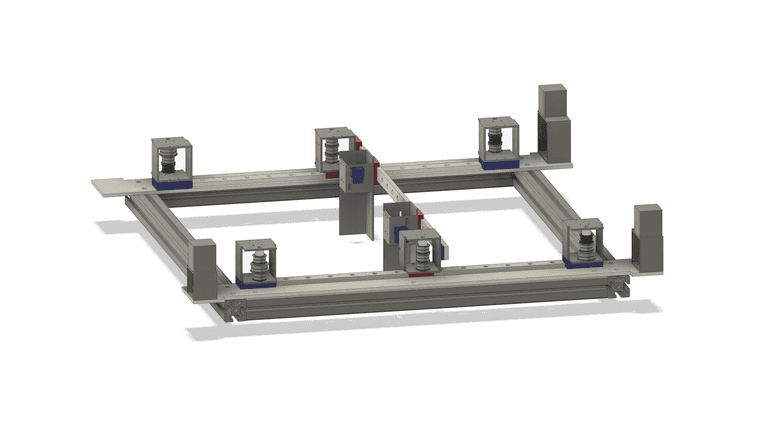
Sure. See below for those details. It's a Prusa P3 Steel, so the Z axis has 2 motors. It is level to the Y axis. The bed is leveled using a .1mm metal feeler gauge. It's a 3mm aluminum bed with Printbite on top. I have a 3 point leveling setup, and it is fairly level, not perfect like cast aluminum plate. The first layer as all layers are .2mm. I don't have any extra extrusion parameters. The extruder is calibrated, so I get 100mm when extruding 100mm. I am not using mesh compensation setup.
Home all
G91 ; relative positioning
G1 H2 Z5 F12000 ; lift Z relative to current position
G1 H1 X-205 Y-205 F1800 ; move quickly to X and Y axis endstops and stop there (first pass)
G1 H2 X5 Y5 F12000 ; go back a few mm
G1 H1 X-205 Y-205 F600 ; move slowly to X and Y axis endstops once more (second pass)
G90 ; absolute positioning
G1 X0 Y0 F6000 ; go to first bed probe point
G91 ; relative positioning
G1 H1 Z-305 F600 ; move Z down stopping at the endstop
G1 H2 Z3 F600 ; go back a few mm
G1 H1 Z-305 F120 ; move slowly to Z axis endstop once more (second pass)
G90 ; absolute positioning
G92 Z0.1 ; set Z position to axis minimumHome X
G91 ; relative positioning
;G1 H2 Z5 F12000 ; lift Z relative to current position
G1 H1 X-205 F1800 ; move quickly to X axis endstop and stop there (first pass)
G1 H2 X5 F2400 ; go back a few mm
G1 H1 X-205 F600 ; move slowly to X axis endstop once more (second pass)
G90 ; absolute positioningHome Y
G91 ; relative positioning
G1 H2 Z5 F12000 ; lift Z relative to current position
G1 H1 Y-205 F1800 ; move quickly to Y axis endstop and stop there (first pass)
G1 H2 Y5 F12000 ; go back a few mm
G1 H1 Y-205 F600 ; move slowly to Y axis endstop once more (second pass)
G1 H2 Z-5 F12000 ; lower Z again
G90 ; absolute positioningHome Z
G91 ; relative positioning
G1 H1 Z-305 F600 ; move Z down stopping at the endstop
G1 H2 Z3 F600 ; go back a few mm
G1 H1 Z-305 F120 ; move slowly to Z axis endstop once more (second pass)
G90 ; absolute positioning
G92 Z0.1 ; set Z position to axis minimumConfig.g
; General preferences
G90 ; send absolute coordinates...
M83 ; ...but relative extruder moves
M550 P"P3 Steel" ; set printer name; Network
M552 S1 ; enable network
M586 P0 S1 ; enable HTTP
M586 P1 S0 ; disable FTP
M586 P2 S1 ; enable Telnet; Drives
M569 P0 S1 ; physical drive 0 goes forwards
M569 P1 S1 ; physical drive 1 goes forwards
M569 P2 S0 ; physical drive 2 goes backwards
M569 P3 S1 ; physical drive 3 goes forwards
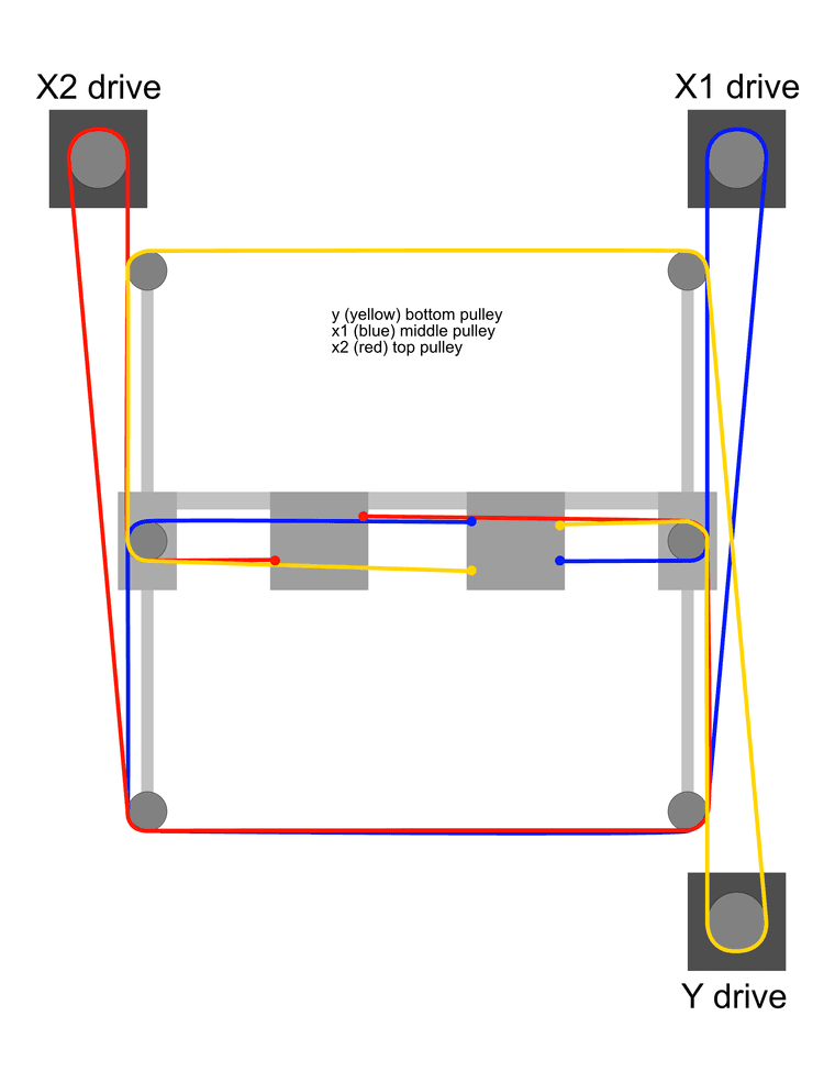
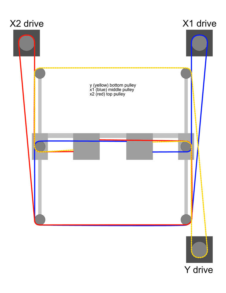
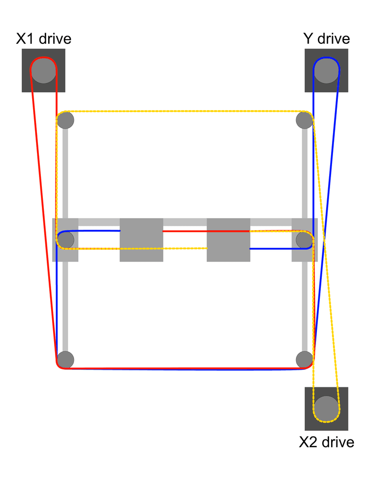
M584 X0 Y1 Z2 E3 ; set drive mapping
M350 X128 Y128 Z128 E128 I0 ; configure microstepping without interpolation
M92 X640.00 Y640.00 Z3200.00 E2335.5 ; set steps per mm
M566 X900.00 Y900.00 Z12.00 E1500.00 ; set maximum instantaneous speed changes (mm/min)
M203 X12000.00 Y12000.00 Z180.00 E12000.00 ; set maximum speeds (mm/min)
M201 X1400.00 Y1400.00 Z50.00 E9000.00 ; set accelerations (mm/s^2)
M906 X1200 Y1200 Z1000 E1400 I30 ; set motor currents (mA) and motor idle factor in per cent
M84 S30 ; Set idle timeout; Axis Limits
M208 X0 Y-13 Z0 S1 ; set axis minima
M208 X200 Y195 Z300 S0 ; set axis maxima; Endstops
M574 X1 S1 P"!xstop" ; configure active-high endstop for low end on X via pin xstop
M574 Y1 S1 P"!ystop" ; configure active-high endstop for low end on Y via pin ystop
M574 Z1 S1 P"!zstop" ; configure active-high endstop for low end on Z via pin zstop; Z-Probe
M558 P0 H2 F120 T6000 ; disable Z probe but set dive height, probe speed and travel speed
M557 X0:200 Y0:200 S1 ; define mesh grid; Heaters
M308 S0 P"bedtemp" Y"thermistor" T100000 B4066 C9.264103e-8 ; configure sensor 0 as thermistor on pin bedtemp
M950 H0 C"bedheat" T0 ; create bed heater output on bedheat and map it to sensor 0
M143 H0 S120 ; set temperature limit for heater 0 to 120C
M307 H0 A62.4 C118.9 D3.0 B0 S1.00 ; disable bang-bang mode for the nozzle heater and set PWM limit
M308 S1 P"e0temp" Y"thermistor" T100000 B4725 C7.06e-8 ; configure sensor 1 as thermistor on pin e0temp
M950 H1 C"e0heat" T1 ; create nozzle heater output on e0heat and map it to sensor 1
M143 H1 S300 ; set temperature limit for heater 1 to 300C
M307 H1 A387.2 C120.9 D3.1 B0 S1.00 ; disable bang-bang mode for the nozzle heater and set PWM limit; Fans
M950 F0 C"fan0" Q500 ; create fan 0 on pin fan0 and set its frequency
M106 P0 S0 H-1 ; set fan 0 value. Thermostatic control is turned off
M950 F1 C"fan1" Q500 ; create fan 1 on pin fan1 and set its frequency
M106 P1 S1 H-1 ; set fan 1 value. Thermostatic control is turned off
M950 F2 C"fan2" Q500
M106 P2 S1 H1 T100; Tools
M563 P0 D0 H1 F0 ; define tool 0
G10 P0 X0 Y0 Z0 ; set tool 0 axis offsets
G10 P0 R0 S0 ; set initial tool 0 active and standby temperatures to 0C; Custom settings are not defined
M207 S3 R-0.1 F6000 T6000 Z0.1 ; Firmware retraction F is retract mm/m and T is detract mm/m
M572 D0 S0.8 ; pressure advance; Miscellaneous
M911 S10 R11 P"M913 X0 Y0 G91 M83 G1 Z3 E-5 F1000" ; set voltage thresholds and actions to run on power loss -
RE: first layer height
HI All,
I feel like I am still having an issue with this. My first layer is clearly being smashed down. I have a G92 Z0.1 set, and Slic3r has a .2mm layer height on all layers. it's as if the first layer is dishing out filament for .2mm layer but in reality it seems the first layer is at .1mm. It's flatter than all the other layers. What could I be doing wrong?
-
RE: Duet Wifi adding .1mm layer height from Slic3r file
I just ran a print that was 4mm, and DWC showed 4.1. The layer height was .2mm, so there should have been 20 layers. It printed 21. When I remove the zhop from Slic3r, the file shows as 4mm.
I posted another thread here where I felt like my first layer is being smashed down. It apparently is because it is printing the first layer at .1mm and the rest at .2mm.
I would rely on firmware retraction, but the zhop is a bit too slow compared to Slic3r. I posted on the Prusa Slic3r forum, and the conclusion was that because the preview was showing the correct height it was not a Slic3r issue.
What could be causing this?
-
RE: Duet Wifi adding .1mm layer height from Slic3r file
@droftarts said in Duet Wifi adding .1mm layer height from Slic3r file:
@mlaustin6 Looks like you've got 0.1mm Z lift enabled. eg:
G1 Z0.200 G1 Z0.300 G1 X21.372 Y128.527 G1 Z0.200 G1 E2.90000 F6000.00000 G1 F990 G1 X23.026 Y128.104 E2.95070 G1 X24.117 Y128.013 E2.98319 G1 X28.273 Y128.012 E3.10661 ...
Moves to layer height, lifts 0.1mm, travel move, then drops down to start printing. DWC is reports the full height of the print, including this, so your object is 6mm high, but there's Z lift moves that mean the full travel is 6.1mm.
Ian
I do. But I also have it enabled on Cura. And Cura files report the right height. I guess it isn't a big deal as long as the layer heights and initial layer are correct.
-
RE: Duet Wifi adding .1mm layer height from Slic3r file
I'm using DWC 2.0.4 with firmware 3.0.
The end gcode is as follows:
M104 S0 ; turn off extruder
M140 S0 ; turn off bed
G28 X0 Y0; home X and Y axis
M107 ; turn fan off
M84 ; disable motorsIt's any file, so here is a recent one. y lm8uu carriage.gcode
-
Duet Wifi adding .1mm layer height from Slic3r file
Hi All,
I don't have this problem with Cura. Slic3r is adding .1mm in layer height. Here is a picture from duet web control. Is that a bug, and is it really adding layer height to the print or just showing it in web control?
-
RE: first layer height
I think Z0.1 did the trick rather than Z.1. Thank you.
-
RE: first layer height
@Phaedrux said in first layer height:
@chrishamm said in first layer height:
You set the Z coordinate before the second homing move. Put your G92 Z.1 code at the end of the file.
That last long z move doesn't have a H1 so it's not homing anything.
I added that. Strange the RRF 3.0 generator did not include that while the older generator did.
-
RE: first layer height
@chrishamm said in first layer height:
You set the Z coordinate before the second homing move. Put your
G92 Z.1
code at the end of the file. Also, you may want to remove the lastG1 X0 Y0
code or at least put aG1 Z3
before it.I put G92 Z0.1 at the end. I added the zero. Why remove G1 X0 Y0? I want homing to go there. What does G1 Z3 do? Would that be so it doesn't crash into the board?
-
RE: first layer height
I am sure. I have a Prusa i3 steel, and I leveled the bed with one of those .1mm flat steel tools. My first layer height is .2mm. It makes no sense for a z probe for me as the machine is older, and it never really needs leveling once set.