Duet3D Logo Duet3D
    • Tags
    • Documentation
    • Order
    • Register
    • Login
    1. Home
    2. remopini
    3. Posts
    • Profile
    • Following 0
    • Followers 0
    • Topics 3
    • Posts 32
    • Best 1
    • Controversial 0
    • Groups 0

    Posts made by remopini

    • RE: Duet 3 "lite"

      Alternatively, I could imagine a fully modular "core" Duet3 board that has only Ethernet/Wifi, control interface IO (LCD/I2C/...) and CAN-FB on it and everything else is connected using various types of tool boards:

      • a N * "stepper driver + end stops"
      • a N * "temp out + temp sensor"
      • a "hot end combo" [the existing one]
      • a N * pwm fan + GPIO

      That way, people could only pay for what they need at the time, mix and match what is needed (need 20 drivers? just add more tool boards) and upgrade/reuse as time goes on (new features only require new tool boards, not a new core board, or a faster processor/more oompf just needs a new core, but the periphery stays the same)... you get the drift.

      Then switch to RJ45 for CAN-FB, because those come in twisted pair and are dirt cheap (which cannot be said for RJ11)

      posted in Duet Hardware and wiring
      remopiniundefined
      remopini
    • RE: Duet 3 "lite"

      Sounds interesting, but that is probably not what I was referring to...

      If you use the tools board(s) for your extruder(s), you still need the three stepper drivers for X/Y/Z movement, but you don't need the hotend components (i.e. extruder drivers, head temp probe, head heater out, head fans, z-probe, ...), so the board could be simplified quite a bit.

      The board basically still needs "the rest".

      The Duet3 with it's $300 price tag is a substantial chunk of cash, so anything to reduce the price would be welcome.

      posted in Duet Hardware and wiring
      remopiniundefined
      remopini
    • Duet 3 "lite"

      Are there any plans to make a "lite" version of the Duet 3 board for people only planning to use the CAN-FD port for hotend(s)?

      There is a lot of (costly) hardware on the Duet3 that is not relevant if using a CAN-FD type setup.

      posted in Duet Hardware and wiring
      remopiniundefined
      remopini
    • RE: DWC2 bug: heater names not displayed correctly

      @DIY-O-Sphere It's not fans, it's heaters and showing tools instead of heaters in a temperature chart is a bad idea, because there isn't necessarily one heater for one tool (a tool could have 2 or more heaters or none).

      posted in Duet Web Control
      remopiniundefined
      remopini
    • RE: DWC2 bug: heater names not displayed correctly

      @SIam You can still switch (by clicking on the blue "Bett" or "Werkzeug 0"), but it is highly annoying 🙂

      posted in Duet Web Control
      remopiniundefined
      remopini
    • RE: DWC2 bug: heater names not displayed correctly

      @wilriker Sure, here you go:
      Board: Board: Duet Ethernet 1.04
      Firmware: RepRapFirmware for Duet 2 WiFi/Ethernet 3.0 (2020-01-03b3)
      DWC: Duet Web Control 2.0.4

      Sanitized config.g:

      ; Drives
      M569 P0 S0                              ; physical drive 0 goes backwards (X)
      M569 P1 S0                              ; physical drive 1 goes backwards (Y)
      M569 P2 S1                              ; physical drive 2 goes forwards (Z)
      M569 P3 S0                              ; physical drive 3 goes backwards (E0)
      M584 X0 Y1 Z2 E3                        ; set drive mapping
      M350 X16 Y16 Z16 E16 I1                 ; configure microstepping with interpolation
      M92 X80.00 Y80.00 Z400.00 E450.00       ; set steps per mm
      M566 X900.00 Y900.00 Z120.00 E120.00    ; set maximum instantaneous speed changes (mm/min)
      M203 X6000.00 Y6000.00 Z1800.00 E1200.00; set maximum speeds (mm/min)
      M201 X500.00 Y500.00 Z20.00 E250.00     ; set accelerations (mm/s^2)
      M906 X600 Y800 Z800 E800 I30            ; set motor currents (mA) and motor idle factor in per cent
      M84 S30                                 ; Set idle timeout
      
      ; Axis Limits
      M208 X0 Y0 Z0 S1                        ; set axis minima
      M208 X300 Y300 Z400 S0                  ; set axis maxima
      
      ; Endstops
      M574 X1 S1 P"!xstop"
      M574 Y1 S1 P"!ystop"
      M574 Z1 S1 P"!zstop"
      
      ; Z-Probe
      M558 P0 H5 F120 T6000                   ; disable Z probe but set dive height, probe speed and travel speed
      M557 X20:280 Y20:280 S65                ; define mesh grid
      G29 S1                                  ; read mesh grid from file
      
      ; Heaters
      M308 S0 P"bedtemp" Y"thermistor" A"Bed" T100000 B4138 ; configure sensor 0 as thermistor on pin bedtemp
      M950 H0 C"bedheat" T0                          ; create bed heater output on bedheat and map it to sensor 0
      M143 H0 S120                                   ; set temperature limit for heater 0 to 120C
      M307 H0 B0 S1.00                               ; disable bang-bang mode for the nozzle heater and set PWM limit
      M308 S1 P"e0temp" Y"thermistor" T100000 B4138  ; configure sensor 1 as thermistor on pin e0temp
      M950 H1 C"e0heat" T1                           ; create nozzle heater output on e0heat and map it to sensor 1
      M143 H1 S280                                   ; set temperature limit for heater 1 to 280C
      M307 H1 B0 S1.00                               ; disable bang-bang mode for the nozzle heater and set PWM limit
      
      ; Fans
      M106 P0 S0 I0 F500 H-1                  ; set fan 0 value, PWM signal inversion and frequency. Thermostatic control is turned off
      M106 P1 S0 I0 F500 H-1                  ; set fan 1 value, PWM signal inversion and frequency. Thermostatic control is turned off
      M106 P2 S1 I0 F500 H1 T45               ; set fan 2 value, PWM signal inversion and frequency. Thermostatic control is turned on
      
      ; Tools
      M563 P0 D0 H1 F1                        ; define tool 0 -> using FAN 1 (fritzed Fan 0)
      G10 P0 X0 Y0 Z0                         ; set tool 0 axis offsets
      G10 P0 R0 S0                            ; set initial tool 0 active and standby temperatures to 0C
      
      ; Custom settings are not defined
      M912 P0 S-3.2                           ; Calibrated MCU Temperature (reading is 3.2° too high)
      
      ; Miscellaneous
      M501                                    ; load saved parameters from non-volatile memory
      

      config-override.g

      M307 H0 A476.5 C791.3 D4.8 S1.00 V23.9 B0
      M307 H1 A1167.0 C239.9 D8.4 S1.00 V23.5 B0
      
      posted in Duet Web Control
      remopiniundefined
      remopini
    • RE: DWC2 bug: heater names not displayed correctly

      @deckingman if you look at my screenshot and post, you can see what I configured. Using the latest available 3.0 firmware bundle from github.

      posted in Duet Web Control
      remopiniundefined
      remopini
    • RE: DWC2 bug: heater names not displayed correctly

      @pipersw That is literally what I just wrote 😉

      posted in Duet Web Control
      remopiniundefined
      remopini
    • RE: DWC2 bug: heater names not displayed correctly

      @deckingman If you look carefully at the OP image, you can see that the names are wrong (heater 1, heater 1, heater 2 instead of heater 1, heater 2, heater 3)

      posted in Duet Web Control
      remopiniundefined
      remopini
    • RE: DWC2 bug: heater names not displayed correctly

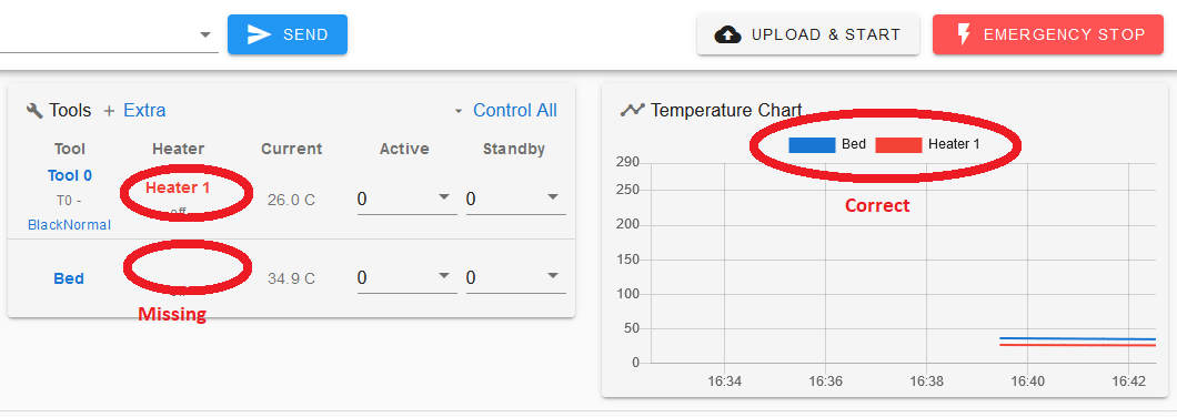
      Actually, on RRF3, if you rename a heater (using M308), it fails to display correctly:

      Config:

      M308 S0 P"bedtemp" Y"thermistor" A"Bed" T100000 B4138
      M308 S1 P"e0temp" Y"thermistor" T100000 B4138
      

      Display:
      dwc_label_error.png

      posted in Duet Web Control
      remopiniundefined
      remopini
    • RE: Another Bed Leveling Weirdness

      @veti Not based on my experience, but it's great if you get that kind of performance out of it 🙂

      posted in Tuning and tweaking
      remopiniundefined
      remopini
    • RE: Another Bed Leveling Weirdness

      @Veti I kind of want to try to get the $50 thing to work first before giving up and going with something completely different. BTW: I wouldn't go with an opto-switch solution, they are rather imprecise.

      As a last resort, I can always try to shield the BLTouch somehow, but finding thin ferromagnetic foil is probably difficult.

      posted in Tuning and tweaking
      remopiniundefined
      remopini
    • RE: Another Bed Leveling Weirdness

      Ok, twiddled a little bit with the mesh definition. Moving everything over a few mm did the trick with the one outlier:
      0_1557211516059_bed level 03.png

      However, the systematic measurement error (that back left corner is NOT 0.48 higher than the other corners) persists.

      With mesh compensation enabled, the nozzle is now basically half a mm higher up in that corner than in all others. So, for whatever reason, there is still a significant measurement error introduced in that corner.

      Current ideas:

      • Since that is the corner where all the cables are, could it be interference? But the very regular error kind of suggests otherwise (interference wouldn't usually be regular)
      • Some mechanical problem that only manifests during probing, but not during normal moves. Also not super likely.
      • The bed magnetism is influencing the measurement. Possible, but nothing I could do anything against, so I'd be limited to use the BLTouch for the initial probe in the front and not do any mesh compensation.
      • Something other I can't think of right now...
      posted in Tuning and tweaking
      remopiniundefined
      remopini
    • RE: Another Bed Leveling Weirdness

      @Twigz The PCB is already turned the "right way", i.e as far away from the hotend as it can (with the mount I have):
      0_1557178723213_20190506_233733.jpg

      Electrically or magnetically, I can't imagine the hotend influencing the BLTouch too much in that setup (the closest active component is more than 40mm from the BLTouch).

      posted in Tuning and tweaking
      remopiniundefined
      remopini
    • RE: Another Bed Leveling Weirdness

      @Twigz @Phaedrux I got a 2.0 (platic pin). The mount is one of those Titan Aero all-in-one mounts, so can't really change the position (I'd have to design my own mount for that). But I can of course change the mesh (or shift it around by some factor). I'll do some trial and error tomorrow to figure out, whether I can find a setup that works. Will update here with any findings.

      posted in Tuning and tweaking
      remopiniundefined
      remopini
    • RE: Another Bed Leveling Weirdness

      @phaedrux Hm... that actually seems to have had a big influence... the level is obviously horrible (books aren't really flat), but there are no outliers.

      Now, the only question is: how do I make the probe less prone to fubar from the magnetic bed? I can't be the only one having issues?

      posted in Tuning and tweaking
      remopiniundefined
      remopini
    • RE: Another Bed Leveling Weirdness

      @jamesm Thx for the tip, however the printer is tuned pretty well and has no play in any of the axes.

      Repeatability is excellent (so no slipping or skipping of any steps) and mechanically, everything is as good as it can be.

      I've successfully printed large parts with the printer with very nice first layers, it's only once I introduced the BL-Touch, that I run into this weird problem.

      The printer still works very fine when not doing a mesh bed leveling and just using it with manual corner leveling.

      posted in Tuning and tweaking
      remopiniundefined
      remopini
    • RE: Another Bed Leveling Weirdness

      Nope, checked that, it's actually the corner closest to the wire mount, so with the most slack. No taut wires anywhere...

      posted in Tuning and tweaking
      remopiniundefined
      remopini
    • RE: Another Bed Leveling Weirdness

      Now, just for fun, I activated that mesh compensation (with the corner shown at +0.64) and it makes the nozzle be about 0.64mm off the bed, so the bed is pretty level, but the mesh compensation with that rising corner is actually complete bogus...

      I'm at a loss why mesh grid compensation seems to measure such crap?

      posted in Tuning and tweaking
      remopiniundefined
      remopini
    • RE: Another Bed Leveling Weirdness

      @Phaedrux Thx for the suggestion!

      Here's the current config:
      M558 P9 H5 F500 T6000 R0.2 A5 B1
      G31 P25 X41 Y0 Z2.200

      I've modified M558 according to your suggestion: M558 P9 H5 F100 T6000 R0.5 A10 B1 S0.003

      Here's the new result:
      0_1557160173242_bed level 02.png

      It looks pretty much the same... Now I totally understand, that the bed might warp up toward the back left corner (although my manual leveling is definitely not off by 0.6mm), but that one point at -0.281mm is complete bogus. What could make the BL-Touch measure just one point completely wrong and all others correctly?

      posted in Tuning and tweaking
      remopiniundefined
      remopini