Duet3D Logo Duet3D
    • Tags
    • Documentation
    • Order
    • Register
    • Login
    1. Home
    2. Spargo
    • Profile
    • Following 0
    • Followers 0
    • Topics 5
    • Posts 13
    • Best 3
    • Controversial 0
    • Groups 0

    Spargo

    @Spargo

    Anthony is a chartered engineer with a background in electrical power engineering. He has a BEng Honours degree in Electrical & Electronic Engineering from the University of Newcastle Upon Tyne. Recently he has started his own business venture, Spargo Engineering, with aims to launch products in home, educational and industrial environments.

    4
    Reputation
    3
    Profile views
    13
    Posts
    0
    Followers
    0
    Following
    Joined Last Online
    Website spargoengineering.online Location United Kingdom

    Spargo Unfollow Follow

    Best posts made by Spargo

    • 7 Colour RGB Lighting Setup

      Hi all,

      As part of my printers I needed some lighting to be controlled by the Duet board itself (Mine is a Duet 2 WiFi 1.04). I've set up some 2N7000 transistors to be controlled on the gate by some unused heater pins on the expansion header.

      The Gcode is below along with a picture of the specific pins I used to control each colour. Your red, green and blue might end up being in a different order than I have in the Gcode. I used a common cathode RGB strip light running on 12V.

      I hope this helps a few people.

      Additionally, it can be included in your config.g with the following line in misc at the end:

      M98 P"/macros/rgb_lighting_setup.g" ; Include RGB Lighting macro in startup process

      If there is no .g in the name when you upload the macro, don't include the .g in the M98.

      RGB_Lighting_Setup.g

      RGB Pins Duet 2 Wifi.png

      posted in Example setups and prints
      Spargoundefined
      Spargo
    • Cantilever bed advice

      Hi, I was wondering if anyone might have any advice on cantilever bed designs.

      The first image shows my existing bed arrangement (GSF R32 rails) which works fine with the exception of some sagging on the unsupported side. It is driven by a single Z axis motor in the middle between the rails and I want to swap to a simpler setup for the metalwork (As seen in image 2).

      The model in image 2 suggests in simulations that it will be significantly stiffer and sag a minimal amount with a 3kg weight, I think it was about 0.2mm at the end. However with the bearing length of only 30mm (Igus N 17) and having tried it with larger bearings (Igus TW-01-20) I'm getting a bit concerned about whether it will run smooth. The Igus T rail guides have a lot of play without a lot of tuning, more than the N guides do, but they also (theoretically) have a much longer area to glide on.

      I haven't been able to tune the T guide blocks up enough to remove all the slack (see image 4 - it shows what it looks like without a rail), and when lifting the bed up they work fine albeit a bit stiff, but when I lower the bed by hand there's a lot of chattering. I have a suspicion that if I flip the bearings upside down that the behaviour would be reversed in this case.

      Am I ignoring too many cantilever design rules or is the chattering simply down the the slack T rail bearings?

      R32 Bed.png

      N17 Bed.png

      20200728_102518.jpg

      20200728_102624.jpg

      posted in 3D Printing General Chat
      Spargoundefined
      Spargo
    • RE: help to print side holes round, but not elliptic

      I haven't got a definite solution that will work at the slicer level as it looks like you already have a small layer height, but one way that works for me is to drill the holes out after they have been printed.

      Another solution may be to add a little cut in the top and bottom of the circle where it goes flat. Your holes wouldn't be perfect circles but they should let you fit a bolt through.
      chunk.png

      posted in Tuning and tweaking
      Spargoundefined
      Spargo

    Latest posts made by Spargo

    • RE: Cantilever bed advice

      Yeah I'm going to move the bearings to the middle and have some spaced. Looking at having a new design for that at either the end of this week or next depending on it I can fit it in or not.

      @mrehorstdmd I've had it actually laying plastic fine with the head moving at those speeds, 0.2mm layers. It's using a volcano with a 0.8mm nozzle and a 48mm high torque stepper motor on the extruder. Moving XY is fine up to 350mm/s.

      posted in 3D Printing General Chat
      Spargoundefined
      Spargo
    • RE: Cantilever bed advice

      Thank you for both your comments, I have very little experience with cantilevers and after all the time I've spent trying to work it out in a cost effective way I thought it best to just ask.

      @sonderzug said in Cantilever bed advice:

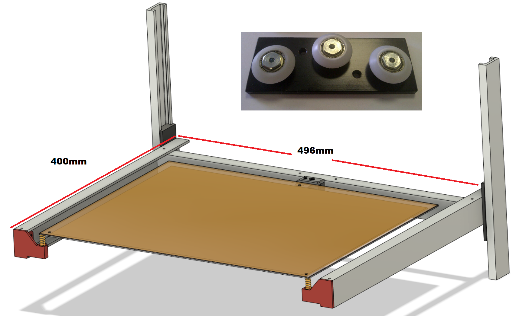
      To eliminate the torque on the bearing block, either move the linear rail to the center of the bed's side (which would have been the sensible thing to do in the first place), or add another bearing block per rail that is spaced to the original one at least half of the distance between rail and the bed's center of gravity.

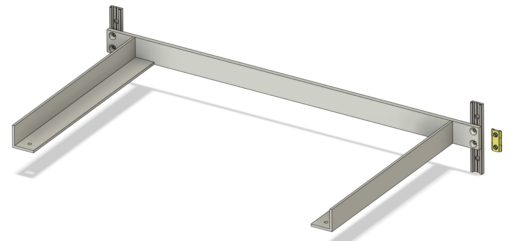
      I thought about that last night, and it seems like what I will have to do. It complicates other parts of the frame so I had been reluctant to try it as I had been trying to keep costs down. To test it from the sides, I should be able to modify the side panels, though it will take some fresh aluminium to span the gap. My contact at a certain company had not commented that the cantilever design would not work when I shared it.

      @mrehorstdmd said in Cantilever bed advice:

      Cantilevers really only work if the guides are very rigid and the bearings have no play. Even at that, there will be a low frequency resonance that will have the bed bouncing like a diving board simply because of the movement of the XY mechanism. You can avoid that by operating the XY mechanism slowly - i.e. print slowly - but who wants to do that?

      I have/had a Cubex Duo printer with a cantilevered bed that printed very nicely as long as print speed was kept <40 mm/sec. Ugh! That probably explains why I haven't done anything with it in a few years.

      If you must cantilever, I think it would be better to use two screws, located as closely as possible to the guides. It would be better still to add a third screw to support the free end of the bed- then it won't bounce.

      Printing slowly is really something I don't want to do. The gantry is capable of printing at 200mm/s. Cantilevering seemed like a sensible choice with strong enough supports as I wanted to keep to a single leadscrew. I don't really want to go to two leadscrews as when I had a Prusa clone years ago it was a huge pain, though that was in part to how poor quality it was. I'll post the results of moving it to the sides when I've found the time.

      posted in 3D Printing General Chat
      Spargoundefined
      Spargo
    • Cantilever bed advice

      Hi, I was wondering if anyone might have any advice on cantilever bed designs.

      The first image shows my existing bed arrangement (GSF R32 rails) which works fine with the exception of some sagging on the unsupported side. It is driven by a single Z axis motor in the middle between the rails and I want to swap to a simpler setup for the metalwork (As seen in image 2).

      The model in image 2 suggests in simulations that it will be significantly stiffer and sag a minimal amount with a 3kg weight, I think it was about 0.2mm at the end. However with the bearing length of only 30mm (Igus N 17) and having tried it with larger bearings (Igus TW-01-20) I'm getting a bit concerned about whether it will run smooth. The Igus T rail guides have a lot of play without a lot of tuning, more than the N guides do, but they also (theoretically) have a much longer area to glide on.

      I haven't been able to tune the T guide blocks up enough to remove all the slack (see image 4 - it shows what it looks like without a rail), and when lifting the bed up they work fine albeit a bit stiff, but when I lower the bed by hand there's a lot of chattering. I have a suspicion that if I flip the bearings upside down that the behaviour would be reversed in this case.

      Am I ignoring too many cantilever design rules or is the chattering simply down the the slack T rail bearings?

      R32 Bed.png

      N17 Bed.png

      20200728_102518.jpg

      20200728_102624.jpg

      posted in 3D Printing General Chat
      Spargoundefined
      Spargo
    • Bed Temperature Zones/Averaging

      I've been thinking recently about how I should measure the temperature of a heated bed I've been making for a larger printer. In a previous role, part of my job involved looking at test data from various products. In that test data we would use multiple temperature probes to find the hotspots, and the average over the entire area too. Thermal imaging was simply not possible.

      If the heated bed of a printer was internally split and controlled in blocks, then theoretically, if there was a significant imbalance of heat, maybe hotspots or cold areas in one specific block, the current could be altered in that area only and bring the temperature in line with other areas.

      I might be wildly overthinking this and I haven't really found anything online other than thermal imaging data, some of those show some areas 10c lower than the measured temperature by the single probe. Does anyone have any thoughts they would like to share on it?

      posted in General Discussion
      Spargoundefined
      Spargo
    • RE: 7 Colour RGB Lighting Setup

      Ah right! I'm using some of the colours for different functions such as completed prints, paused prints, cancelled prints etc. I'm not currently planning on using all of the colours though, but at least they're available for future use.

      posted in Example setups and prints
      Spargoundefined
      Spargo
    • RE: 7 Colour RGB Lighting Setup

      Here's a short video of the attached macro (in the dark!)

      https://youtu.be/sCaVMq7UaOA

      Do you mean a picture of the circuit setup?

      posted in Example setups and prints
      Spargoundefined
      Spargo
    • 7 Colour RGB Lighting Setup

      Hi all,

      As part of my printers I needed some lighting to be controlled by the Duet board itself (Mine is a Duet 2 WiFi 1.04). I've set up some 2N7000 transistors to be controlled on the gate by some unused heater pins on the expansion header.

      The Gcode is below along with a picture of the specific pins I used to control each colour. Your red, green and blue might end up being in a different order than I have in the Gcode. I used a common cathode RGB strip light running on 12V.

      I hope this helps a few people.

      Additionally, it can be included in your config.g with the following line in misc at the end:

      M98 P"/macros/rgb_lighting_setup.g" ; Include RGB Lighting macro in startup process

      If there is no .g in the name when you upload the macro, don't include the .g in the M98.

      RGB_Lighting_Setup.g

      RGB Pins Duet 2 Wifi.png

      posted in Example setups and prints
      Spargoundefined
      Spargo
    • RE: PanelDue 5i not erasing

      Yes it is disconnected from the Duet, the only connection is the USB which I've tried in a USB 2 and USB 3 port.

      posted in PanelDue
      Spargoundefined
      Spargo
    • PanelDue 5i not erasing

      Hi,
      I'm trying to upload updated firmware to the PanelDue 5i I have, but the erase button does not seem to erase anything for me. If I hold it down for a few seconds then press reset, it restarts like I didn't do anything and loads up the menu. It is connected via a USB cable from Samsung but I have also tried it without power just in case it needed to be done when off.

      Any advise that anyone could give me would be appreciated.

      posted in PanelDue
      Spargoundefined
      Spargo
    • RE: help to print side holes round, but not elliptic

      I haven't got a definite solution that will work at the slicer level as it looks like you already have a small layer height, but one way that works for me is to drill the holes out after they have been printed.

      Another solution may be to add a little cut in the top and bottom of the circle where it goes flat. Your holes wouldn't be perfect circles but they should let you fit a bolt through.
      chunk.png

      posted in Tuning and tweaking
      Spargoundefined
      Spargo