Duet3D Logo Duet3D
    • Tags
    • Documentation
    • Order
    • Register
    • Login
    1. Home
    2. TDK
    3. Posts
    • Profile
    • Following 0
    • Followers 1
    • Topics 7
    • Posts 28
    • Best 3
    • Controversial 0
    • Groups 0

    Posts made by TDK

    • RE: Are G2/G3 arcs still broken into G1 segments?

      Very much not a new thing:
      https://github.com/TheLongRunSmoke/g1tog23

      I saw in other posts that the distance is not user-configurable, and is actually not fixed, but it's hard to know if that is still accurate.

      Still a bit disappointed G2/G3 isn't natively supported but it is what it is. I didn't verify the fix in the latest RC.

      posted in General Discussion
      TDKundefined
      TDK
    • RE: How to run gcode commands remotely on a Duet3 + RPi?

      Running sudo /opt/dsf/bin/CodeConsole from the console seems to work.

      Here's my code to log in using Python with the default user/pass. After this, sending commands works:

      tn = telnetlib.Telnet(printer_ip)
      print(tn.read_until(b"login: ").decode('utf=8', errors='ignore'))
      tn.write(b'pi\n')
      print(tn.read_until(b"Password: ").decode('utf=8', errors='ignore'))
      tn.write(b'raspberry\n')
      print(tn.read_until(b"$ ").decode('utf=8', errors='ignore'))
      tn.write(b'sudo /opt/dsf/bin/CodeConsole\n')
      print(tn.read_until(b"Connected!").decode('utf=8', errors='ignore'))
      
      tn.write(b'M114\n')
      sleep(1.0)
      print(tn.read_very_eager().decode('utf=8', errors='ignore'))
      
      posted in General Discussion
      TDKundefined
      TDK
    • How to run gcode commands remotely on a Duet3 + RPi?

      I have a Duet3 6HC board connected with a Raspberry Pi. It works, I can print files, view the web interface, etc. Is there a way I can programmatically (Python) run commands remotely on this setup? I have it set up where I can telnet into the RPi, but obviously entering gcode commands in the console doesn't work.

      I also have a Duet2 Wifi board where I can telnet into the board and just send commands to run them. I'm essentially looking for the same functionality on the Duet3 + SBC setup.

      posted in General Discussion
      TDKundefined
      TDK
    • RE: G2/G3 arcs with R parameter traverse the longer of the two arcs

      @MJLew said in G2/G3 arcs with R parameter traverse the longer of the two arcs:

      The problem is not just when the r parameter is being used. Even with I and J I cannot achieve an arc of less than 180 degrees.

      I can't reproduce this. The following moves through four 90 degree segments of a circle with radius 20 without issue:

      G0 X20 Y0 Z10
      
      G2 I-20 J0 X0 Y-20
      G2 I0 J20 X-20 Y0
      G2 I20 J0 X0 Y20
      G2 I0 J-20 X20 Y0
      
      posted in General Discussion
      TDKundefined
      TDK
    • RE: Wiring problem

      @Grudairian said in Wiring problem:

      Do you have an approach you would recommend?

      Anything that gets rid of the 6A current limitation. If your heater pulls 40W, you're pulling over 3.33A from the 12V line. More because your step-up converter can't be 100% efficient.

      Using directly soldered wires rather than the ATX connector is one solution. Just gotta be mindful of other current limits in the system.

      posted in Duet Hardware and wiring
      TDKundefined
      TDK
    • RE: Wiring problem

      The ATX connector pins are rated to 6A. I think you're just exceeding that limit, or getting close to it. The other connections (screw terminals) aren't the problem.

      If you're using 150W, you're pulling at least 12.5A out of that pin. And since you're using a step-up converter, you would be even higher.

      posted in Duet Hardware and wiring
      TDKundefined
      TDK
    • RE: G2/G3 arcs with R parameter traverse the longer of the two arcs

      @bot Not a typo, just showing the path I'm using. I don't think RRF claims to support negative radii parameters in any capacity, but that's tangential to the original post.

      For clarity, the following two paths produce the same motion on my machine:

      G0 X20 Y0 Z10 F6000
       
      G2 X0 Y-20 R20
      G2 X-20 Y0 R20
      G2 X0 Y20 R20
      G2 X20 Y0 R20
      
      G0 X20 Y0 Z10 F6000
       
      G2 X0 Y-20 R-20
      G2 X-20 Y0 R-20
      G2 X0 Y20 R-20
      G2 X20 Y0 R-20
      
      posted in General Discussion
      TDKundefined
      TDK
    • RE: G2/G3 arcs with R parameter traverse the longer of the two arcs

      It appears in CNC a negative R value will correspond to the arc over 180 degrees and a positive one will correspond to the arc under 180 degrees. Seems reasonable.

      https://www.cnccookbook.com/cnc-g-code-arc-circle-g02-g03/

      In RRF, for my path, a negative R value has the same effect as a positive R value.

      G0 X20 Y0 Z10 F6000
      
      G2 X0 Y-20 R20
      G2 X-20 Y0 R20
      G2 X0 Y20 R20
      G2 X20 Y0 R20
      
      posted in General Discussion
      TDKundefined
      TDK
    • G2/G3 arcs with R parameter traverse the longer of the two arcs

      The G2/G3 arc command can be specified using either the R parameter to describe the radius or the I/J parameter to describe the center of the arc.

      If using the R parameter, unless you describe an arc of exactly 180 degrees, there are exactly 2 arcs which can fit the description, one goes through an angle under 180 degrees and one goes through an angle under 180 degrees. Both clockwise. (Counterclockwise arcs suffer the same issue, of course.)

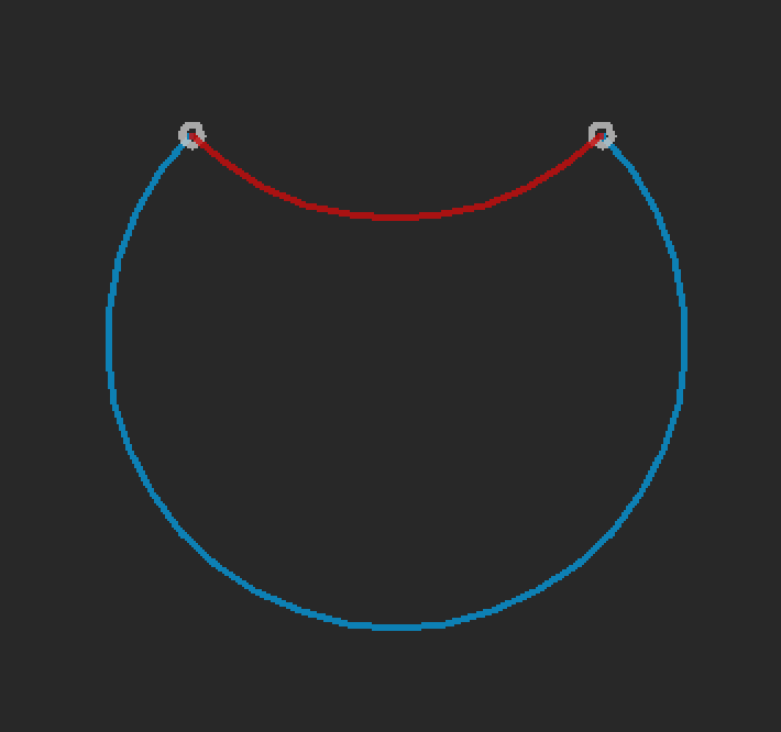
      For example, moving between the two white circles (left to right) here spaced 10 units apart with a counterclockwise arc of radius 7.07, one can construct the shorter (red) arc which traverses 90 degrees or the longer (blue) arc which traverses 270 degrees. Both have the same radius, both start and end at the right points.

      arcs.png

      It appears as though RRF always chooses the longer of the two arcs. At least it does on my machine for the path I just constructed. I would have expected the shorter, since now it appears there is no way to traverse an arc under 180 degrees.

      Is this the intended behavior? It seems like one should never use the R parameter for arcs given this ambiguity and use the (over-constrained) I/J parameters instead. Perhaps there should be another parameter which specifies which of the two arcs to traverse? Or perhaps just use the shorter of the two arcs?

      The Marlin firmware doesn't define the behavior either, but their example has an arc of 90 degrees. I don't have a printer with Marlin on it anymore to test.

      FIRMWARE_NAME: RepRapFirmware for Duet 3 MB6HC FIRMWARE_VERSION: 3.1.1 ELECTRONICS: Duet 3 MB6HC v1.01 or later FIRMWARE_DATE: 2020-05-19b2
      
      posted in General Discussion
      TDKundefined
      TDK
    • RE: True Bed Leveling

      @CaLviNx said in True Bed Leveling:

      Really ? please tell me how can you be 100% of that without physically being there and laying the milled tool plate on a granite surface plate and physically measuring to see if it is warped or not

      I'm going off of this picture by OP:

      @ErwinH78 said in True Bed Leveling:

      11.JPG ![1_1600585544055_Foto 20.09.20, 09 04 12.jpg](Lade 100% hoch)

      in which you can see the bed is clearly non-planar. A warped frame or non-planar XY motion could also cause this.

      Since bed leveling only adjusts the best fit plane, it's not going to remove the one corner that is warped upward.

      posted in Duet Web Control
      TDKundefined
      TDK
    • RE: True Bed Leveling

      Your bed is warped. Auto-leveling isn't going to help here.

      In the height map, look at the three points it uses as the true-leveling probe points. They are all near zero. So it's doing its job.

      The docs say to have probe points near the leadscrews, but really you can have them anywhere and it'll do the least-squares best fit. I use 4 points at each corner and one point in the center and I think the result looks better than using just 3.

      posted in Duet Web Control
      TDKundefined
      TDK
    • RE: Are G2/G3 arcs still broken into G1 segments?

      @dc42 said in Are G2/G3 arcs still broken into G1 segments?:

      G2 and G3 commands are still broken into line segments. However, a G2 or G3 command is much more efficient for the Duet to processes than the equivalent set of G1 commands.

      Thanks for confirming. Does the user have any control over how this is done or is it a hard-coded 0.2mm per segment?

      posted in General Discussion
      TDKundefined
      TDK
    • RE: programming binary "Duet3_SDiap_MB6HC.bin" not found

      In my case, I wasn't even upgrading to 3.x. I was just updating an as-shipped board to the latest version. If release candidate builds have a different update process, that's fine, but I don't think boards should be loaded with an RC build before shipping.

      posted in Firmware installation
      TDKundefined
      TDK
    • Are G2/G3 arcs still broken into G1 segments?

      In the documentation, there is nothing that indicates that G2/G3 commands are broken up into line segments. I know this is what has traditionally been done. Does RRF 3.x still break arcs up into segments? Still a fixed 0.2mm distance per segment?

      The best I could find while searching was this ~2 year old post where dc24 said arcs are broken up into 0.2mm segments:
      https://forum.duet3d.com/topic/7983/g1-vs-g2-g3-for-cnc/6

      I'm trying to avoid ringing issues and wondering if converting lines to arcs and slightly rounding paths prior to printing would help at all.

      posted in General Discussion
      TDKundefined
      TDK
    • RE: Message "Error: Homing failed" even though homing worked

      @Phaedrux said in Message "Error: Homing failed" even though homing worked:

      @TDK said in Message "Error: Homing failed" even though homing worked:

      Same goes for if it only homes 1 or 2 axis in homeall it will then call the homing file of whatever axis is not yet homed.

      Well at least I'm sure this part is correct. I extrapolated to it homing all axis if the file was empty. I'll have to do some testing.

      If I put only M98 P"homex.g" in the homeall.g file, then it does home the Y and Z axes after the X. So it seems you need to home at least something. And in this case, no error message is generated.

      I guess this scheme makes sense if you want to combine X and Y homing into one operation in homeall.g, but then don't want to duplicate the homez.g code.

      posted in General Discussion
      TDKundefined
      TDK
    • RE: Message "Error: Homing failed" even though homing worked

      @Phaedrux said in Message "Error: Homing failed" even though homing worked:

      Technically if you leave homeall.g blank it will then just execute homex homey and homez macros. Same goes for if it only homes 1 or 2 axis in homeall it will then call the homing file of whatever axis is not yet homed.

      This isn't the behavior I see. If I leave homeall.g blank, it does not execute any action and simply returns the error message "Error: Homing failed".

      posted in General Discussion
      TDKundefined
      TDK
    • RE: Message "Error: Homing failed" even though homing worked

      @jay_s_uk said in Message "Error: Homing failed" even though homing worked:

      Typically in your homeall file, you call the macro using M98 P"homez.g" rather than using G28 X

      This fixed the issue. I appreciate the response.

      While searching, I came across this post as well:

      https://forum.duet3d.com/topic/10468/homeall-g-content-cleanup

      It seems using "G28" within homeall.g isn't really allowed (despite it working fine save the error message). I don't really agree with that implementation choice, but it is what it is. On to the next issue.

      posted in General Discussion
      TDKundefined
      TDK
    • RE: Message "Error: Homing failed" even though homing worked

      I'm following the instructions here:
      https://duet3d.dozuki.com/Wiki/Connecting_a_Z_probe

      Which suggests the following for homez.g:

      ; homez.g
      ; called to home the Z axis
      
      G91                ; relative positioning
      G90                ; absoute position
      M401               ; deploy probe
      G1 X163 Y129 F1800 ; move to middle of bed plus probe offsets
      G30                ; home z0
      M402               ; retract probe
      

      Are you saying that is incorrect?

      I'll agree they are a bit complicated. Some of that is due to sensorless homing, some due to me wanting to offset coordinates by a few mm. I don't see how that would be causing the error.

      I commented out M401 and M402. It still works, but the result (error message) is the same.

      posted in General Discussion
      TDKundefined
      TDK
    • Message "Error: Homing failed" even though homing worked

      I'm getting the error message "Error: Homing failed" when issuing a "G28" command with no arguments. Despite the error message, the printer homes correctly.

      If I issue a "G28 X" or "G28 Y" or "G28 Z" command, the printer homes the corresponding axis and no error message is output.

      Pictures are not uploading correctly...
      ![0_1599405502148_g28_homing_failed.png](Uploading 100%)

      9/6/2020, 11:02:36 AM	G28
      Error: Homing failed
      9/6/2020, 11:01:57 AM	G28 Z
      9/6/2020, 11:01:46 AM	G28 Y
      9/6/2020, 11:01:39 AM	G28 X
      

      This is on a CoreXY machine, but I'm also seeing the same thing on my Ender3 cartesian.

      What am I doing wrong?

      M98 P"0:/macros/FIRMWARE_INFO_M115"
      FIRMWARE_NAME: RepRapFirmware for Duet 3 MB6HC FIRMWARE_VERSION: 3.1.1 ELECTRONICS: Duet 3 MB6HC v1.01 or later FIRMWARE_DATE: 2020-05-19b2
      
      ; homeall.g
      ; called to home all axes
      
      G28 X
      G28 Y
      G28 Z
      
      ; homex.g
      ; called to home the X axis
      
      M400
      M913 X30 Y30
      M915 X Y S1 R2
      M400
      G92 X0
      G91
      G1 H2 Z2 F300
      G1 H1 X-500 F4800
      G1 X20 F2400
      G1 H2 Z-2 F300
      G90
      M400
      M913 X100 Y100
      M400
      
      ; offset by 1mm
      G0 X1 F6000
      G92 X0
      
      ; homey.g
      ; called to home the Y axis
      
      G90
      G0 X0 F4800
      M400
      M913 X30 Y30
      M915 X Y S1 R2
      M400
      G92 Y0
      G91
      G1 H2 Z2 F300
      G1 H1 Y500 F2400
      G1 Y-20 F2400
      G1 H2 Z-2 F300
      G90
      M400
      M913 X100 Y100
      M400
      
      ; offset by 1mm
      G0 Y1 F6000
      G92 Y0
      
      ; homez.g
      ; called to home the Z axis
      
      G91                ; relative position
      G1 Z10 H2 F600
      G90                ; absolute position
      G1 X0 Y-24 F6000   ; move to middle of bed plus probe offsets
      M401               ; deploy probe
      G30                ; home z0
      M402               ; retract probe
      G1 Z10 F600        ; Move z up a little
      
      ; Configuration file for Duet 3 (firmware version 3)
      ; executed by the firmware on start-up
      ;
      ; generated by RepRapFirmware Configuration Tool v3.1.4 on Wed Jul 29 2020 21:58:06 GMT-0400 (Eastern Daylight Time)
      
      ; General preferences
      G90                                          ; send absolute coordinates...
      M83                                          ; ...but relative extruder moves
      M550 P"TankXY"                               ; set printer name
      M669 K1                                      ; select CoreXY mode
      
      ; Network
      M552 P0.0.0.0 S1                             ; enable network and acquire dynamic address via DHCP
      M586 P0 S1                                   ; enable HTTP
      M586 P1 S0                                   ; disable FTP
      M586 P2 S0                                   ; disable Telnet
      
      ; Drives
      M569 P0.0 S1                                 ; physical drive 0.0 goes backwards
      M569 P0.1 S0                                 ; physical drive 0.1 goes backwards
      M569 P0.2 S0                                 ; physical drive 0.2 goes backwards
      M569 P0.3 S0                                 ; physical drive 0.3 goes backwards
      M569 P0.4 S0                                 ; physical drive 0.4 goes backwards
      M569 P0.5 S1                                 ; physical drive 0.5 goes forwards
      
      M584 X0.1 Y0.0 Z0.2:0.3:0.4 E0.5             ; set drive mapping
      M350 E16 Z16 I1                              ; configure microstepping without interpolation
      M350 X16 Y16 I1                              ; configure microstepping with interpolation
      M92 X80.00 Y80.00 Z1600.00 E420.00           ; set steps per mm
      ; M350 X256 Y256 Z256 I0
      M566 X900.00 Y900.00 Z12.00 E120.00          ; set maximum instantaneous speed changes (mm/min)
      ; max Z speed set to 300 to avoid resonance on lead screws
      M203 X6000.00 Y6000.00 Z300.00 E1200.00      ; set maximum speeds (mm/min)
      M201 X500.00 Y500.00 Z250.00 E250.00         ; set accelerations (mm/s^2)
      M906 X1000 Y1000 Z1000 E1000 I30             ; set motor currents (mA) and motor idle factor in per cent
      M84 S15                                      ; Set idle timeout
      
      ; Axis Limits
      ; X range = 214mm true range, limited to 212mm
      ; Y range = 218mm, limited to 216mm
      M208 X-106 Y-108 Z0 S1                       ; set axis minima
      M208 X106 Y108 Z220 S0                       ; set axis maxima
      
      ; Endstops
      M574 X1 S3                                   ; configure sensorless endstop for low end on X
      M574 Y2 S3                                   ; configure sensorless endstop for high end on Y
      
      ; BL-Touch probe
      M558 P9 C"io7.in" H5 F300 T6000              ; set Z probe type to bltouch and the dive height + speeds
      M950 S0 C"io7.out"                           ; create servo pin 0 for BLTouch
      ; to move print head closer to bed, increase Z value here
      G31 X0 Y24 Z2.88 P500                       ; offset from hot end nozzle
      
      ; set up grid probing points
      M557 X-75:75 Y-75:75 S37.5                   ; Define mesh grid
      
      ; Heaters
      ; S0 = bed thermistor
      M308 S0 P"temp0" Y"thermistor" T100000 B4138 ; configure sensor 0 as thermistor on pin temp0
      ; H0 = bed heater
      M950 H0 C"out0" T0                           ; create bed heater output on out0 and map it to sensor 0
      M307 H0 B1 S1.00                             ; disable bang-bang mode for the bed heater and set PWM limit
      M140 H0                                      ; map heated bed to heater 0
      M143 H0 S120                                 ; set temperature limit for heater 0 to 120C
      
      ; S1 = hot end thermistor
      M308 S1 P"temp1" Y"thermistor" T100000 B4138 ; configure sensor 1 as thermistor on pin temp1
      ; H1 = hot end heater
      M950 H1 C"out1" T1                           ; create nozzle heater output on out1 and map it to sensor 1
      M307 H1 B0 S1.00                             ; disable bang-bang mode for heater  and set PWM limit
      
      ; S2 = mcu temperature
      M308 S2 Y"mcu-temp" A"MCU"
      
      ; Fans
      ; F0 = out9 = part cooling fan
      ; F1 = out6 = hot end heat sink fan
      ; F2 = out4 = case fan
      ; F3 = out5 = case fans
      
      ; set part cooling fan on out9
      M950 F0 C"out9" Q25000
      M106 P0 S0.0
      
      ; set hot end fan on out6
      M950 F1 C"!out6" Q2000
      ; thermostatic control
      M106 P1 T40:90 H1 S1.0
      
      ; F2 and F3 = case fans on out4 and out5
      M950 F2 C"!out4" Q2000
      M950 F3 C"!out5" Q2000
      ; thermostatic control
      M106 P2 T50:80 H2 S1.0
      M106 P3 T50:80 H2 S1.0
      
      ; Tools
      M563 P0 S"Extruder" D0 H1 F0                 ; define tool 0
      G10 P0 X0 Y0 Z0                              ; set tool 0 axis offsets
      G10 P0 R0 S0                                 ; set initial tool 0 active and standby temperatures to 0C
      
      ; Custom settings are not defined
      
      ; Miscellaneous
      M501                                         ; load saved parameters from non-volatile memory
      T0                                           ; select first tool
      

      I see that other people have had similar issues, but the proposed solutions do not work for me. In some cases, it's unclear if the issue was really solved:

      https://forum.duet3d.com/topic/5538/homing-failed-error-even-though-it-succeeded
      Solution: use "G30" instead of "G30 S-1", presumably worked

      https://forum.duet3d.com/topic/15645/error-homing-failed-also-no-print-time-estimation-given
      Soluton: none posted apart from update firmware, maybe it worked, maybe not.

      https://forum.duet3d.com/topic/2970/error-homing-failed-on-any-g28-situation/11
      Solution: update firmware, but then another user claims it isn't fixed.

      Edit: corrected homeall.g script.
      posted in General Discussion
      TDKundefined
      TDK
    • RE: M584 won't swap X/Y motor axes

      Oh, I think I get it. I need to reverse direction of one motor.

      Yeah that solved it. The CoreXY kinematics were complicating the understanding of what was going on.

      posted in General Discussion
      TDKundefined
      TDK