Duet 2 Ethernet and SBC
-
@deadwood83 R100,R101,R105 on the SPI lines on the Duet 2 side are 47R. There are relatively short lines from those resistors to the relevant pins. External copper is 2Oz and these are 0.25mm traces. internal solder is 1Oz, same trace width.
Where we use those buffers on the Duet 3 we don't have series resistors in the circuit as well as the buffers so the 470R is probably unnecessary
-
@arhi said in Duet 2 Ethernet and SBC:
@deadwood83 said in Duet 2 Ethernet and SBC:
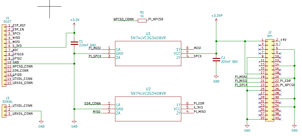
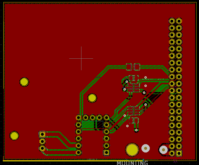
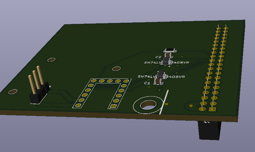
The schematics/PCB
awesome
") thanks
thanks
Did you made this in kicad and exported to easyeda or you made it directly in easyeda. I can redraw it in kicad but if you already have it in kicad it would save me some time
I made it in EasyEDA. I keep trying to go to KiCAD but snap to grid just... drives me completely insane. I wager that will become pretty much mandatory once I graduate beyond 2-layer.
@smoki3 said in Duet 2 Ethernet and SBC:
@deadwood83 Cool design. I use a would use a similar one but with an integrated 5V DCDC converter to power the raspberry. Otherwise you need an external one which is not so pretty and easy to use.
I also integrated the same pin layout as on the raspberry to use a simple ribbon cable.
But actually the firmware is the first thing which need to be fixed
I fear that any buck which would fit on a reasonable sized board would not be up to snuff. I have seen LMs and MP bucks burn Pi's faaaar too many times to feel comfortable putting one in one of my designs. Also, when you put power to the pi through GPIO it is my understanding that it bypasses a significant section of input protection. I will stick to $10 10A converters. Much safer to run 10-30% of a very cheap piece of kit's rating IMO when it has questionable pedigree.
RE: Ribbon cable; My personal preference is to twist MISO/MOSI lines from individual conductors. CS has a buffer resistor near the node end (and doesn't have the sensitivity of the other 3) and 3v3_Pi isn't near the SPI pins anyway. Plus anybody soldering to a 3d printer controller probably has some dupont connectors #DiabloEternal
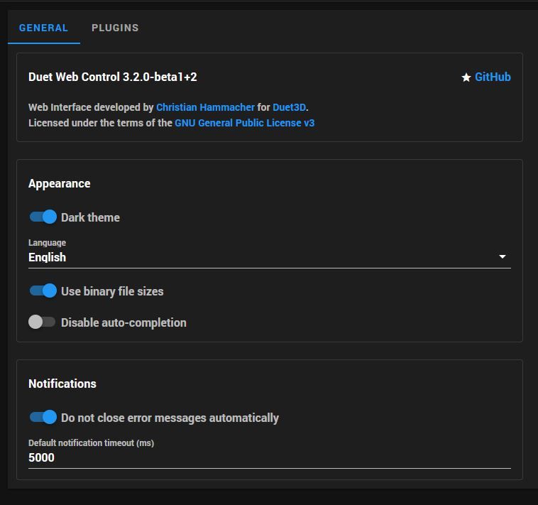
RE: Firmware fix; from the RF3.2 excel spreadsheet -
Duet+SBC support
Duet 2 SBC support Done

@PCR said in Duet 2 Ethernet and SBC:
@deadwood83 Wrote you a PM
Replied
@bearer said in Duet 2 Ethernet and SBC:
@deadwood83 said in Duet 2 Ethernet and SBC:
2 layer FR4 1.6mm 1-Oz copper PCB
4 layer and 2 Oz for the Duets
Understood, my impedance calcs were based on my cheap PCB though. I am not worried about the Duet circuitry since it comes from more capable designers than I
@T3P3Tony said in Duet 2 Ethernet and SBC:
@deadwood83 R100,R101,R105 on the SPI lines on the Duet 2 side are 47R. There are relatively short lines from those resistors to the relevant pins. External copper is 2Oz and these are 0.25mm traces. internal solder is 1Oz, same trace width.
Where we use those buffers on the Duet 3 we don't have series resistors in the circuit as well as the buffers so the 470R is probably unnecessary
Thanks Tony. I have updated my PCB layout to remove that and will put a simple solder bridge once my PCBs arrive. Being 0403 size, it could probably be bridged with a c-store lighter! (I will use my T12 station)
-
@deadwood83 said in Duet 2 Ethernet and SBC:
I keep trying to go to KiCAD but snap to grid just
I'm still getting used to KiCAD since I don't have access to licenced Altium any more and since I don't allow "cured" software on my computers had to find alternative and KiCAD is kinda best I managed to find.The grid thing .. what I do is I make my own set of trace widths and my own grid values and then I switch between them ... there's probbly a better way to do it but...
I wanted to steal from your design the dimensions - position of headers vs that hole on top and the screw and ... but since I'm doing a push-on daughterboard (I used eth modules so remove eth board, plug in this one) with 5A DCDC and maybe some leds I might actually don't need to worry about positions...
-
There is a PCB in the EasyEDA link which is closed off and with through-holes for the ethernet board for those who want to just stick on some headers and go. The components are low-profile so it will fit top or bottom.
The only things you would need to add are 5v buck and some LEDs. Look in the EasyEDA project for ethernetPCB and you will find it there, ready for you.

-
@deadwood83 said in Duet 2 Ethernet and SBC:
RE: Firmware fix; from the RF3.2 excel spreadsheet -
Duet+SBC support
Duet 2 SBC support DoneUnfortunately this support is currently limited to Duet 2 only, i.e. no DueX2/DueX5 connected.
EDIT: the above is still considered a preliminary limitation and it is being worked on to get this resolved.
Explicitly pulling the ESP_Enable line down (for a still present Wifi module) should be added to firmware soon.
-
@deadwood83 seen that but I want to make it different (a pcb that will plug directly into rpi + duet), but looks like easier to measure distance of the hole from the header than reworking the easyeda project ... I'll share the project when I make it
-
@arhi said in Duet 2 Ethernet and SBC:
but looks like easier to measure distance of the hole from the header than reworking the easyeda project .
the kicad sources for the duet gives you all the measurements, with the measurement tool in kicad? I used that to print a piece to glue some dupont headers to and keep the holes for the stand-offs.
-
@bearer said in Duet 2 Ethernet and SBC:
the kicad sources for the duet
HAAHA I did not see the tree from the forest ... thanks, I was trying to move the tiny board to kicad, danced with calipers... loading kicad source of the duet2eth board did not at any point come to mind
thanks, that solves my problem 100% -
I went with a WAAAAAY bigger board to avoid using any cables. Something like this .. I kept all 3 mount holes for the wifi board, expanded the board outside of the duet pcb so that this board can plug directly, in the same time, into duet and into rpi so no cables .. I also added a header for RX/TX for uart1 on the duet since it's not used any more might be useful for cnc pendant or second screen or ..
I still suck at kicad big time but this should work .. kicad files who wanna play, maybe make better
-
-
@bearer said in Duet 2 Ethernet and SBC:
@arhi said in Duet 2 Ethernet and SBC:
into duet and into rpi so no cables
interesting!
I just ordered assembled boards from jlpcb (trying them out for the first time, normally I was using seed, itead and dirty) should be here in 5-6 days so will say how it works (or not
) -
@arhi I agree, it is an interesting idea to design without cables.
-
@JoergS5 said in Duet 2 Ethernet and SBC:
@arhi I agree, it is an interesting idea to design without cables.
made sense to me, we'll see, fedex normally arrive inside 7 days so .. not a long time to wait and not expensive (2$ for 5 pcb's, 15$ assembly+parts, 15$ fedex) ideal board to try out the jlcpcb system
-
Have you ever had a DHL driver scream at you then throw a package at your face while shouting "Social distancing?"
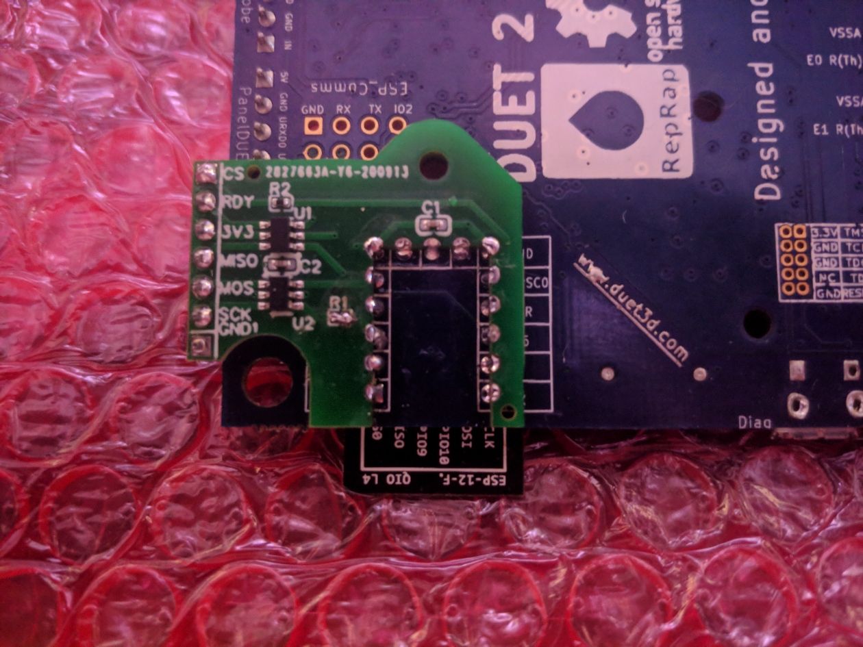
Yeah, me either. They do leave things at my door and run away though. Jumper for scale.
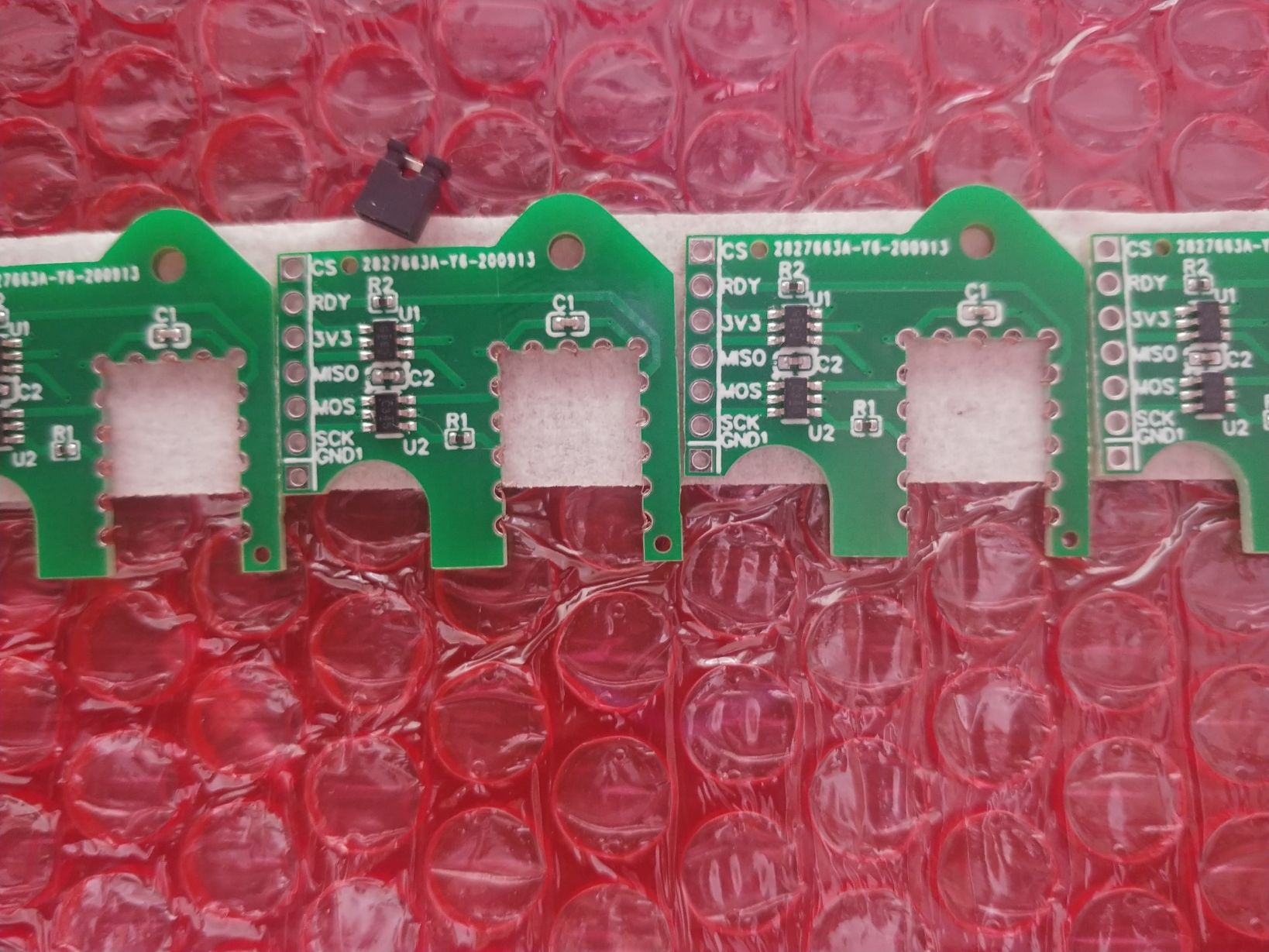
Look at those tiny resistors. Aren't they cute? you could accidentally desolder them with an intense gaze. I'm going to do just that to R1 and at least once to an R2.
-
Any news about a firmware fix for SBC and Duex5?
-
Dry run looks super promising. I goofed though and realized I do not have any 24->5V USB-C power delivery units.

Now I need to build out a male-male harness, throw this on my delta, solder a second board to the delta duet, and try a real run.
-
@deadwood83 would be cool to have an integrated 5V regulator
I used this one:
They are super small. But I have to wire them with a cable directly from 24V
-
@smoki3 it would still require traces back to the 24v input. Also, the coils used on those (and more often the B or C-lot mp1584) are intolerant of feedback on the 12/24v line. Not to mention the RF noise it generates and the extra heat to dissipate. When the fail, they fail open. If that overwhelmed the 3.3v stepdown on the pi it would probably damage the input buffers on the PCB; so then you're either doing micro soldering or putting on a whole new daughterboard just to avoid running one tap from the PSU and a dedicated 5V for the pi.. in addition to having to buy a new pi.
Add that to quadrupling the PCB cost due to needing to stretch all the way back to the inputs and suddenly that mod costs Pi+PCB+Time+Risk to damaging mainboard. Add a voltage regulator after the input and the PCB SMT cost skyrockets due to small quantity. It's just not worth it and defeats the tiny form factor. One of my goals was to give people an option to add SBC support without having to redesign mainboard housings.
In comparison, a 50W Meanwell 5V supply is ~USD $13 and includes a meshed RF-blocking shell (for the high frequencies that could interfere with comms); voltage regulation; transient handling; and is not exposed to feedback spikes from, say, a ceramic-potted heater cartridge.
The design is fully open source. I won't ever put a cheap digital buck, but nothing stopping you from dipping a toe into PCB creation and doing it yourself. That's how I got started, and I highly recommend it. It's pretty fun!
My 5v PSU and USB-C hookup should be here Wednesday. Kudos to the firmware team for the excellent work on the Duet2 SBC support. I have not been able to derive a synthetic test which causes it to fail where standalone does not. I still have 4 PCBs I am willing to send at the cost of postage to homes in the continental USA.
-
Wow awesome what you guys put together here!!
Have some of you thought about a "official" step-by-step guide for duet 2 ethernet and wifi? -
@arhi I'd be interested in getting a board or two if you have spares (-;