Duet3D PCB delta printer effector sneak preview
-
Yes it's possible to use ribbon cable to carry power if you use enough conductors. My Ormerod 1 uses ribbon cable to power the 10A bed heater. I think it's a 40 way cable using 19 ways in each direction to carry the heater current and 2 for the thermistor. To connect a hot end this way, then in order to allow for using a 12V 50W heater plus fans etc. you would need about 28 conductors, making it quite a wide ribbon cable and difficult to wrap around a Bowden tube on a delta printer. A!so, you would want to have the Duet designed with a matching ribbon cable connector on it.
For future intelligent hot end designs and Duets, I'm looking at using one RJ11 connector to carry the signals and a 2-pin power connector of some sort to carry 12V or 24V power. But for now the smart effector is designed to work with the current generation of Duet electronics (and perhaps other electronics too) so that is a not a possibility. On my own delta I plan to change the wiring to use two 8-core cables: one for the signals, and the other for the heater (using 2 pairs of conductors in parallel) and fans.
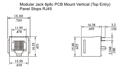
If you are going to dual 8 core (16 total) you could use the 4 twisted pair RJ45 plugs mated to PCB mounted 8 way RJ45 sockets and silicone 8 core wire should be flexible enough.
-
@CaLviNx:
I was thinking along the lines of doubling up spreading the load across the connectors, 24v on a 60 watt heater cartridge comes out at 2.5 amps so if you use for example
16 way flat ribbon cable 28 AWG (7x36) Stranded 300V that should work.Just in the same way some are powering nema 17's with CAT5/6
But hey I'm a Mech Eng not Electrical….
Doubling up pins is bad practice. There's no way to guarantee the load is shared evenly - if the resistance of one is a bit different, the load seeks the lower resistance path.
Ask Rigidbot how it worked out to spread a load across multiple pins. Here's an example:
https://plus.google.com/101640661041406923828/posts/SL7EXPS1Rro
Molex MicroFit connectors are rated for 5 amps and would be a more suitable choice.
Nema17 over Cat5/6 is reasonable, as they make RJ45 connectors rated at 1.5 amps which is typical for a stepper motor. The biggest issue using network cable on a stepper motor is the repeated flexing.
-
You can get stranded core RJ45 that's still rated for 1.5 amps.
-
Yes, but not everyone knows that. Better stated: The biggest issue with network cable on stepper motors is folks using solid core cable which can't handle the flexing.
-
Doubling up pins is bad practice.
Bad practice… hahahaha
Try being in the field and the company man is screaming to get the job done !!! If you think Deepwater Horizon was far fetched on that front think again... anyway
"if" I was doubling up on pins I would be doing it for myself and not worry about a pissing contest of who did what where or when and live with the consequences of that choice.
So to get back on topic I see a need (for me anyway) for the following to go the effector.
X2 wires for the Heater cartridge. (of a suitable gauge to handle the required load)
X2 wires for the Hot end temp signal
X1 "live" to feed the hot end fan, cooling fan and any lighting (again of a suitable gauge to handle the required load)
X3 "signal earths" for controlling the fans & lightingAnd any additional wires to cover the contact sensor requirements
-
Yes, but not everyone knows that. Better stated: The biggest issue with network cable on stepper motors is folks using solid core cable which can't handle the flexing.
Hence my comment to David about using flexible silicone wire, which in hindsight was a stupid comment as he more than likely understands that better than most.
-
Hi guys
Any update on this kit being released. Yet
-
There is a 5-week lead time on the modified E3D heatsinks, and the order has only just been placed. We are waiting for feedback from beta testers before we finalise the rest of the design, but unless that results in major changes then we can manufacture production electronics more quickly than that. So I hope we will be shipping kits about 6 weeks from now.
-
Is there any chance to get two or four of those heatsinks either through you or e3d around that time? I'd love to use the screw-top mount over the groove mount.
-
There is a 5-week lead time on the modified E3D heatsinks, and the order has only just been placed. We are waiting for feedback from beta testers before we finalize the rest of the design, but unless that results in major changes then we can manufacture production electronics more quickly than that. So I hope we will be shipping kits about 6 weeks from now.
I would like to buy the effector and plate adapters, dont need anything E3d I already have an adapter system 90% ready to allow me to use my Prometheus hot end in the same manner as your pics show. I just need the effector to allow me to 100% match the hole spacing.
-
Once we have finalised the design I will publish the dimensions
-
Do you guys have any ETA on this? I'm really excited about it, looks perfect for what I need.
-
See my previous post.
-
Six weeks, sorry. I was a little overzealous!
-
Just stumbled across this thread and flipped through the pages without reading every line, so I apologize, if that has been asked before:
Have you considered putting LEDs on the PCB-bottom? -
Have a look at https://duet3d.com/wiki/Smart_effector_and_carriage_adapters_for_delta_printer you will see if you scroll down to the underneath pic of it that there is indeed LED's on the bottom surface as well as 2 showing thru the top to indicate Hotend on and Sensor trigger.
-
I'm in for one once this gets going as well.
I know adding an IMU was discussed earlier for autolevelling and calibration purposes, but I would another potential use as well: magball disconnect detection. It should be very easy to tell if the effector goes out of level by more than 10 degrees or so, and shut down the printer so no more damage is done. I would take an IMU on board for that purpose alone.
-
David, what sort of accuracy/repeatability results are you finding for fully assembled ball-ball spacing across rod pitch and array angularity as well as ball planar relations? Standard PCB hole-hole tolerance is +/- 0.10mm. Add to that slop in the ball stud hole fit, ball-to-stud concentricity ( don't know how Haydn specifies this ) as well as PCB warp and stud flange face to ball center. Serious tolerance budgeting - it might be interesting to see what a three sigma distribution looks like. On the other hand deltas often seem to work fairly well even with some pretty low tolerance angle ball stud (ugh!) printed effector platforms.
-
Wow…I've just now noticed this topic. What a stunning design, I really love the concept!
I was just planning on refitting my delta with wider rod spacing and a piezo Z-probe effector, but I really like this design better than any printable one. For folks with machines like my UltiBots 250 V-Slot...how would we go about mounting the carriage adapters to our existing wheeled carriages like these?
https://github.com/UltiBots/K250VS/blob/master/Experimental/umbee_carriage_45.stl
Also, if you haven't already is there any chance you could work with the Zesty Nimble crew so they can design a mount for this new heatsink/effector arrangement?
Cheers!