Cura uses concentric circles to fill will be a layer of lag
-
I don't understand the question.
-
@alankilian The second circle prints vibration, other circles will not vibrate
-
After removing the E parameter in the second gcode, there will be no freezes. It is preliminarily believed that the extrusion command parameter will conflict with other movement parameters. Even if the extrusion speed, acceleration, speed change is increased to a large extent, it will also be stuck
-
Motion video with E parameters in the second circle
EAA7EBE743E9CB9A0F54CB66640C68B2.mp4Motion video without E parameter in the second lap9F1DD4E87A58FBD740D55F4C5D791780.mp4
-
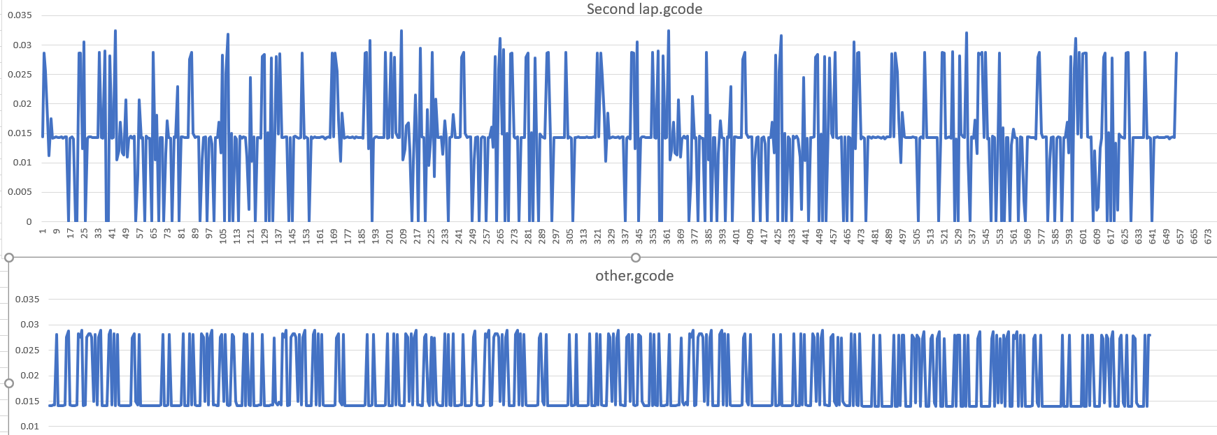
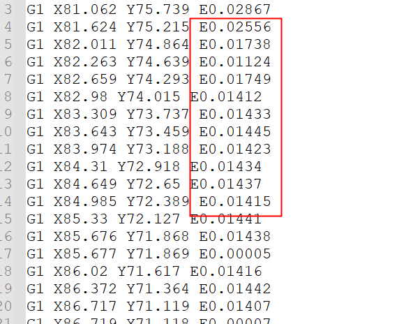
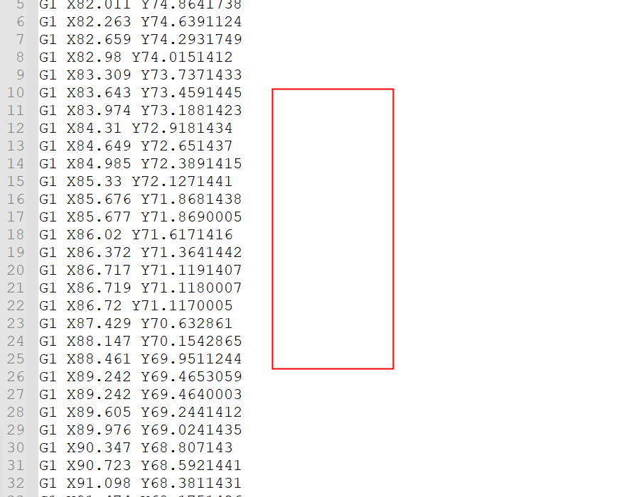
E parameters of 2 files are taken out separately for comparison
-
I conducted a test, and if the extruder grows close to 0 and there are many cuts nearby, there will be vibration.
-
@fly Try tweaking the line width and reslice.
-
@fly, do you have pressure advance enabled? If yes, try setting it to zero. If that stops the stuttering, then the reason may be that Cura is not generating moves with a uniform extrusion rate. We have a GCode analyser that can look at this in more detail.
Duet WiFi hardware designer and firmware engineer
Please do not ask me for Duet support via PM or email, use the forum
http://www.escher3d.com, https://miscsolutions.wordpress.com -
After testing, the DUET2 motherboard will not vibrate when the heating is not turned on. When the heating is turned on, it will vibrate even if the set temperature is 0. What I get roughly means that as long as the E extruder is involved, it will vibrate.
Test version 3.3 b1/3.3 b2
-
@dc42 There is no advance squeeze setting found in my config,So duet officially needs to be tested
-
@dc42 When the E command is close to 0, the gcode parser should ignore the value of E and only keep the XY parameter, which should solve this problem
-
@fly post your config.g file (copy the text and use the code snippet tool). That way we can see any issues in there, and have a go at recreating the problem.
-
@engikeneer It has nothing to do with the configuration file, gcode parsing problem. You can test the gcode I sent, or modify the filling mode of cura.
-
This is the configuration tested on my duet2 motherboard on ender3
; Configuration file for Duet WiFi (firmware version 3)
; executed by the firmware on start-up
;
; generated by RepRapFirmware Configuration Tool v3.2.3 on Sat Apr 17 2021 11:41:47 GMT+0800 (中国标准时间); General preferences
G90 ; send absolute coordinates...
M83 ; ...but relative extruder moves
M550 P"My Printer" ; set printer name; Network
M552 S1 ; enable network
M586 P0 S1 ; enable HTTP
M586 P1 S0 ; disable FTP
M586 P2 S0 ; disable Telnet; Drives
M569 P0 S0 ; physical drive 0 goes forwards
M569 P1 S0 ; physical drive 1 goes forwards
M569 P2 S0 ; physical drive 2 goes forwards
M569 P3 S1 ; physical drive 3 goes forwards
M584 X0 Y1 Z2 E3 ; set drive mapping
M350 X16 Y16 Z16 E16 I1 ; configure microstepping with interpolation
M92 X80.00 Y80.00 Z400.00 E420.00 ; set steps per mm
M566 X900.00 Y900.00 Z60.00 E120.00 ; set maximum instantaneous speed changes (mm/min)
M203 X6000.00 Y6000.00 Z180.00 E1200.00 ; set maximum speeds (mm/min)
M201 X500.00 Y500.00 Z20.00 E250.00 ; set accelerations (mm/s^2)
M906 X800 Y800 Z800 E800 I30 ; set motor currents (mA) and motor idle factor in per cent
M84 S30
; Axis Limits
M208 X0 Y0 Z0 S1 ; set axis minima
M208 X230 Y210 Z200 S0 ; set axis maxima; Endstops
M574 X1 S1 P"xstop" ; configure active-high endstop for low end on X via pin xstop
M574 Y1 S1 P"ystop" ; configure active-high endstop for low end on Y via pin ystop
M574 Z1 S2 ; configure Z-probe endstop for low end on Z; Z-Probe
M558 P1 C"zprobe.in" H5 F120 T6000 ; set Z probe type to unmodulated and the dive height + speeds
G31 P500 X0 Y0 Z2.5 ; set Z probe trigger value, offset and trigger height
M557 X15:215 Y15:195 S20 ; define mesh grid; Heaters
M308 S0 P"bedtemp" Y"thermistor" T100000 B4138 ; configure sensor 0 as thermistor on pin bedtemp
M950 H0 C"bedheat" T0 ; create bed heater output on bedheat and map it to sensor 0
M307 H0 B1 S1.00 ; enable bang-bang mode for the bed heater and set PWM limit
M140 H0 ; map heated bed to heater 0
M143 H0 S120 ; set temperature limit for heater 0 to 120C
M308 S1 P"e0temp" Y"thermistor" T100000 B4138 ; configure sensor 1 as thermistor on pin e0temp
M950 H1 C"e0heat" T1 ; create nozzle heater output on e0heat and map it to sensor 1
M307 H1 B0 S1.00 ; disable bang-bang mode for heater and set PWM limit
M143 H1 S280 ; set temperature limit for heater 1 to 280C; Fans
M950 F0 C"fan0" Q500 ; create fan 0 on pin fan0 and set its frequency
M106 P0 S0 H-1 ; set fan 0 value. Thermostatic control is turned off
M950 F1 C"fan1" Q500 ; create fan 1 on pin fan1 and set its frequency
M106 P1 S1 H1 T45 ; set fan 1 value. Thermostatic control is turned on; Tools
M563 P0 D0 H1 F0 ; define tool 0
G10 P0 X0 Y0 Z0 ; set tool 0 axis offsets
G10 P0 R0 S0 ; set initial tool 0 active and standby temperatures to 0C; Custom settings are not defined
-
This is the configuration I used on a large machine, using the stm32 motherboard, and using an external driver
; Configuration file for Fly-E3 (firmware version 3)
; executed by the firmware on start-up
;
; generated by RepRapFirmware Configuration Tool v3.2.1-LPC on Mon Jan 18 2021 15:03:24 GMT+0800 (中国标准时间); General preferences
G90 ; send absolute coordinates...
M83 ; ...but relative extruder moves
M550 P"My Printer" ; set printer name; Network
M552 S1 ; enable network
M586 P0 S1 ; enable HTTP
M586 P1 S0 ; disable FTP
M586 P2 S0 ; disable Telnet; Drives
M569 P0 S1 T5.0:2.0:5:0.4 R1 ; physical drive 0 goes forwards using default driver timings
M569 P1 S0 T5.0:2.0:5:0.4 R1 ; physical drive 1 goes backwards using default driver timings
M569 P2 S1 T1.0:1.0:0.2:0.2 ; physical drive 2 goes forwards using A4988 driver timings
M569 P3 S0 T1.0:1.0:0.2:0.2 ; physical drive 3 goes forwards using A4988 driver timings
M569 P4 S0 T1.0:1.0:0.2:0.2
M584 X0 Y1 Z2 E3:4 ; set drive mapping
M350 X16 Y16 Z16 E16:16 I1 ; configure microstepping with interpolation
M92 X266.67 Y266.67 Z1600.00 E92.65:92.65 ; 脉冲
M566 X500.00 Y500.00 Z10.00 E80.00:80.00 ; 最大速度变化mm/秒
M203 X30000.00 Y30000.00 Z600.00 E4800.00:4800.00 ;最大速度 (mm/min)
M201 X700.00 Y700.00 Z100.00 E700.00:700.00 ; 加速度 (mm/s^2)
M906 X800 Y800 Z800 E800:800 I30 ; set motor currents (mA) and motor idle factor in per cent
M84 S30 ; Set idle timeout; Axis Limits
M208 X0 Y0 Z0 S1 ; set axis minima
M208 X600 Y600 Z63 S0 ; set axis maxima; Endstops
M574 X2 S1 P"!xstopmax" ; configure active-high endstop for high end on X via pin !xstop
M574 Y1 S1 P"!ystop" ; configure active-high endstop for low end on Y via pin !ystop
M574 Z1 S1 P"!zstop" ; configure active-high endstop for low end on Z via pin !zstop; Z-Probe
M558 P9 H4.5 F360 T8000 C"^probe" ; disable Z probe but set dive height, probe speed and travel speed
M557 X15:565 Y15:565 S28 ;
G31 P1000 X-30. 5 Y-3 Z2.891 ;
M950 S0 C"servo0" ;
; Heaters
M308 S0 P"bedtemp" Y"thermistor" T100000 B4138 ; configure sensor 0 as thermistor on pin bedtemp
M950 H0 C"bed" T0 ; create bed heater output on bed and map it to sensor 0
M307 H0 R0.162 C136.2 D3.10 S1.00 V0.0 ; disable bang-bang mode for the bed heater and set PWM limit
M140 H0 ; map heated bed to heater 0
M143 H0 S120 ; set temperature limit for heater 0 to 120C
M143 H0 S120 ; set temperature limit for heater 0 to 120C
M308 S1 P"e0temp" Y"thermistor" T100000 B4138 ; configure sensor 1 as thermistor on pin e0temp
M950 H1 C"e0heat" T1 ; create nozzle heater output on e0heat and map it to sensor 1
M307 H1 R2.457 C230.3 D4.65 S1.00 V0.0 ; disable bang-bang mode for heater and set PWM limit
M143 H1 S280 ; set temperature limit for heater 1 to 280C; Fans
M950 F0 C"fan0" Q500 ; create fan 0 on pin fan0 and set its frequency
M106 P0 S0 H-1 ; set fan 0 value. Thermostatic control is turned off; Tools
M563 P0 D0 H1 F0 ; define tool 0
G10 P0 X0 Y0 Z0 ; set tool 0 axis offsets
G10 P0 R0 S0 ; set initial tool 0 active and standby temperatures to 0C
M563 P1 D1 H1 F0 ; define tool 1
G10 P1 X0 Y0 Z0 ; set tool 1 axis offsets
G10 P1 R0 S0; Custom settings are not defined
M575 P1 S0 B57600
; Miscellaneous
T0 ; select first tool
M280 P0 S160 -
@fly I just ran your gcode files on my machine. CoreXY with Duet Wifi on RRF3.2.2.
other.gcode seems to have printed fine - smooth & no jerking motion at all.
second-lap.gcode does produce a vibrating motion like you describe. If however, I slow it down a lot (e.g. to 20%), the motion it smooth, but I can see the circle it prints isn't quite perfect (you can see the facets from the stl file and the line width varies a little)I think that the issue you are seeing is related to some non-uniform extrusion rate as DC42 suggested. You can see in the snippet of the gcode you posted that the extrusion rate is varying. It jumps from ~0.01438mm to 0.00005mm in one line (line 16 to 17), so it goes from extruding to stopping, then back to extruding again in three lines of gcode (in about 10ms of time at a motion speed of 4800mm/min). I calculate that as a speed change of about 160mm/min inboth directions for your extruder (-160mm/min then +160mm/min) which is higher than your jerk setting of 120mm/min (and 80mm/min on the other printer). There are some even higher jumps in the problem file looking at your graphs. The extruder has to be able to keep up with the motion requested and will slow/stop the xyz motion if it can't. Again, as DC42 said, if you have any pressure advance set (I do), this may make things worse as the pressure advance will be applied on top of the extisting fluctuations. All this is the Duet behaving as expected I think.
So your options are:
- Increase your extruder jerk (M566) significantly so that it doesn't impact/limit the motion planning
- Change your slicer settings so the gcode they output is more consistent (e.g. alter your line widths so the additional line is a more consitent size like @mrehorstdmd suggested)
- Change your stl file. It might be that the facets on the inner/outer surfaces are making the rim thickness of your part vary, hence the problem line has all these non-uniform extrusion rates.
E3D TC with D3Mini and Toolboards.
Home-built CoreXY, Duet Wifi, Chimera direct drive, 2x BMG, 300x300x300 build volume
i3 clone with a bunch of mods -
Seems like expected behaviour from Cura actually. How it handles single width fill lines is pretty abysmal.
You can try this version of Cura that has some fixes for that behaviour. https://github.com/smartavionics/Cura/releases
Or try Prusa Slicer which has really good gap fill behaviour by comparison.
-
@engikeneer The M83 command is used in the gcode of RRF, which is not 0.01438mm to 0.00005mm. After extruding 0.01438mm, it will extrude 0.00005mm relative to 0.01438mm.
Modifying the speed and acceleration of the extruder is invalid. I have tried it many times.
Running this kind of gcode in marlin firmware will not have this use case, so I think the firmware program may also have bugs. -
@mrehorstdmd said in Cura uses concentric circles to fill will be a layer of lag:
@fly Try tweaking the line width and reslice.
@phaedrux said in Cura uses concentric circles to fill will be a layer of lag:
Seems like expected behaviour from Cura actually. How it handles single width fill lines is pretty abysmal.
You can try this version of Cura that has some fixes for that behaviour. https://github.com/smartavionics/Cura/releases
Or try Prusa Slicer which has really good gap fill behaviour by comparison.
Also if Cura is an amazing program is not perfect. I'm agree...the issue is in Cura. I lost age to try to figure it out and even on the Ultimaker forum there is no solution.
Just try to use different width for internal or external lines (or for the nozzle in general - 0,41 etc - , find the right combo and save the profile for this specific part). Sometime we expect that the program is capable to slice as better as we can image but it is not.
The vibration is generated by the slicer because the mess of micro variations. For my delta I can confirm this. (hundreds of attempts)
The concentric patter is the worst in Cura. (just in case, disable "spiralized", it is good for vase but not for thick wall with infill) -
@fly my calculations are still correct. To extrude 0.01438mm in the short segments yor gcode has at 4800mm/min, the extruder has to be moving at about 160mm/min. For the next line, to extrude 0.00005mm, the extruder has to be moving at about 0mm/min. Then on the following line it is back up to 160mm/min. It never goes backwards, but that is a significant change in speed required (both decelerating then accelerating) and is larger than your extruder jerk.
How comparable are your extruder accel, speed & jerk settings on your Marlin machine?
There may be some differences in how Marlin and RRF work (e.g. are you using the Marlin junction deviation?), but fundamentally RRF will respect the motion limits for every axis (including the extruder) and will slow down the motion if these are being violated.