Duet3D Logo Duet3D
    • Tags
    • Documentation
    • Order
    • Register
    • Login

    Anybody wants a stepper motor analyzer?

    Scheduled Pinned Locked Moved
    General Discussion
    56
    281
    31.6k
    Loading More Posts
    • Oldest to Newest
    • Newest to Oldest
    • Most Votes
    Reply
    • Reply as topic
    Log in to reply
    This topic has been deleted. Only users with topic management privileges can see it.
    • Th0mpyundefined
      Th0mpy @Dogma2k
      last edited by

      @dogma2k With either of those you should not need a jumper on the options. They both have 400mv/a rating, so you should be good.

      Usually the team that scores the most points wins the game.

      Dogma2kundefined 1 Reply Last reply Reply Quote 0
      • Th0mpyundefined
        Th0mpy @rjenkinsgb
        last edited by

        @rjenkinsgb What about just some stepper motor cables, and hack the end off? Something like this maybe: https://www.amazon.com/RuiLing-Stepper-Motor-Cables-HX2-54/dp/B07QHTG82K/ref=sr_1_3?keywords=stepper+motor+cable&qid=1637721866&sr=8-3

        Usually the team that scores the most points wins the game.

        rjenkinsgbundefined 1 Reply Last reply Reply Quote 0
        • rjenkinsgbundefined
          rjenkinsgb @Th0mpy
          last edited by rjenkinsgb

          @th0mpy said in Anybody wants a stepper motor analyzer?:

          What about just some stepper motor cables, and hack the end off?

          I have those already - it's the mating header connector I need, so I can unplug from a motor and connect "inline" between that cable and the motor.

          These, in other words:
          https://uk.rs-online.com/web/p/pcb-headers/1755419/
          https://www.ebay.co.uk/itm/143627995609

          I got a pack of these instead, and I can use two motor cables on the analyzer with one of these to link to the existing motor cable:
          https://www.ebay.co.uk/itm/383225801147

          (I'm not buying from the profiteering sellers on principle).

          Six pin plug to socket extension cables would have been ideal, but I cannot find any place actually in the UK selling them.

          Robert J.

          Printers: Overlord pro, Kossel XL+ with Duet 6HC and "Frankentron", TronXY X5SA Pro converted to E3D toolchange with Duet 6HC and 1LC toolboards.

          1 Reply Last reply Reply Quote 0
          • rjenkinsgbundefined
            rjenkinsgb
            last edited by

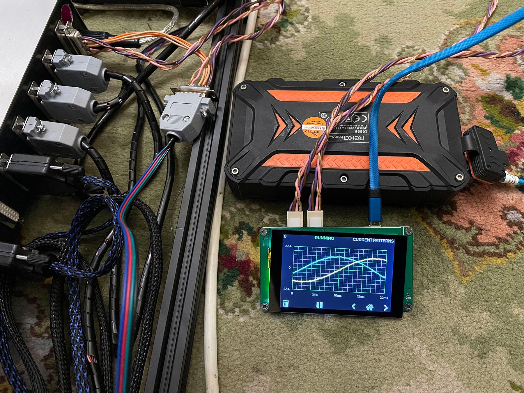
            The Mouser TMCS1101A4BQDT ICs seem to work perfectly!

            I've made a harness to connect in to the axis motor sockets on the control box, which is fine for those (but the extruders are run from individual toolboards).

            [I have printed an enclosure, but then discovered I don't have any thin double-sided tape to attach the display... I'll get some later on].

            IMG_5484_sm.jpg

            IMG_5487.jpg

            IMG_5485.jpg

            Robert J.

            Printers: Overlord pro, Kossel XL+ with Duet 6HC and "Frankentron", TronXY X5SA Pro converted to E3D toolchange with Duet 6HC and 1LC toolboards.

            zaptaundefined 1 Reply Last reply Reply Quote 0
            • zaptaundefined
              zapta @rjenkinsgb
              last edited by

              @rjenkinsgb, very nice build!

              A couple of notes:

              1. Theoretically the analyzer needs only 4 wires to measure the currents of the two coils. You can build a harness that has only 4 wires with Y splitting on both ends.
              2. For double sided tape for the TFT, I had good experience with this kind of thermal tapes. They hold well and designed to be isolating. https://www.amazon.com/gp/product/B072JJD2ND . I also use them between the Pico and the PCB for extra isolation.
              3. You mention residual current (0.04A in the picture). I presume that you set the zero in the Settings screen.
              zaptaundefined rjenkinsgbundefined 2 Replies Last reply Reply Quote 0
              • zaptaundefined
                zapta @zapta
                last edited by

                A question for the people that uses various current sensors, how do tell the firmware what is the mv/A sensitivity of the sensor you use?

                I don't think that this kind of equipment needs to be supper accurate in the current measurement but it's nice to keep it reasonably close, e.g. +/-5%.

                rjenkinsgbundefined 1 Reply Last reply Reply Quote 0
                • Dogma2kundefined
                  Dogma2k @Th0mpy
                  last edited by

                  @th0mpy
                  Thank you for your explanation.
                  I have now found a couple of TMCS1101A4BQDT that I wanted to order.

                  It doesn't really matter what kind of stepper I analyze. I wanted to install the analyzer on my NEMA23 as a permanent display

                  1 Reply Last reply Reply Quote 0
                  • rjenkinsgbundefined
                    rjenkinsgb @zapta
                    last edited by

                    @zapta said in Anybody wants a stepper motor analyzer?:

                    A couple of notes:

                    1. Theoretically the analyzer needs only 4 wires to measure the currents of the two coils. You can build a harness that has only 4 wires with Y splitting on both ends.
                    2. For double sided tape for the TFT, I had good experience with this kind of thermal tapes. They hold well and designed to be isolating. https://www.amazon.com/gp/product/B072JJD2ND . I also use them between the Pico and the PCB for extra isolation.
                    3. You mention residual current (0.04A in the picture). I presume that you set the zero in the Settings screen.

                    I realise only two through connections are monitored, but the harness needs two connectors at either end anyway..

                    To fix the display, I put a few strips of kapton on the back & over the rear of the motor connectors to ensure good insulation, then some generic thin double sided tape to hold things together.

                    Yes, it has been zero'd - the readings fluctuate randomly +/- a small amount with no connections. When I first turned the unit on, it read somewhere around 300 - 400mA on each channel.

                    It's a really nice design, the options and screen responsiveness are great. Playing around with it, I realised it can do for something else I have been intending to make for some time - an encoder tester for machine tool systems.

                    If I add a pair of analog differential inputs with selectable gain in place of the current sensors on one, it can monitor either sine or digital encoders & linear scale signals - pretty much just change the Amps indication for Volts!

                    Robert J.

                    Printers: Overlord pro, Kossel XL+ with Duet 6HC and "Frankentron", TronXY X5SA Pro converted to E3D toolchange with Duet 6HC and 1LC toolboards.

                    1 Reply Last reply Reply Quote 0
                    • rjenkinsgbundefined
                      rjenkinsgb @zapta
                      last edited by

                      @zapta said in Anybody wants a stepper motor analyzer?:

                      A question for the people that uses various current sensors, how do tell the firmware what is the mv/A sensitivity of the sensor you use?

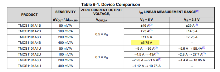
                      If you get some TMCS1101A4BQDT ICs, they are the same sensitivity as the original ones.

                      Robert J.

                      Printers: Overlord pro, Kossel XL+ with Duet 6HC and "Frankentron", TronXY X5SA Pro converted to E3D toolchange with Duet 6HC and 1LC toolboards.

                      zaptaundefined 1 Reply Last reply Reply Quote 0
                      • zaptaundefined
                        zapta @rjenkinsgb
                        last edited by

                        @rjenkinsgb said in Anybody wants a stepper motor analyzer?:

                        TMCS1101A4BQDT

                        The datasheet of the TMCS1101A4BQDT suggests that it requires 5V supply. Does it work well with 3.3V?

                        524a2d7f-b32a-4c0b-a748-b8b01e234573-2021-11-25_21-03-52.png

                        Th0mpyundefined 1 Reply Last reply Reply Quote 0
                        • Th0mpyundefined
                          Th0mpy @zapta
                          last edited by

                          @zapta It seems that either 3.3v or 5v work just fine. The limits are just a little different.

                          Usually the team that scores the most points wins the game.

                          zaptaundefined 1 Reply Last reply Reply Quote 0
                          • zaptaundefined
                            zapta @Th0mpy
                            last edited by zapta

                            @th0mpy said in Anybody wants a stepper motor analyzer?:

                            @zapta It seems that either 3.3v or 5v work just fine. The limits are just a little different.

                            Good to know. Thanks. Yes, 3.3 will cause saturation for +/-5.75A @400mv/A but we don't need that full range, and it is specified for 3.3V for the other ranges.

                            1 Reply Last reply Reply Quote 0
                            • Dogma2kundefined
                              Dogma2k
                              last edited by

                              So that the prototype housing of the AWD Stepper Motor Analyzer fits quite well, just adjust a few small things.

                              Front.jpg
                              Back.jpg

                              zaptaundefined 1 Reply Last reply Reply Quote 1
                              • zaptaundefined
                                zapta @Dogma2k
                                last edited by

                                @dogma2k said in Anybody wants a stepper motor analyzer?:

                                AWD Stepper Motor Analyze

                                Wow! That's a nice design.

                                1 Reply Last reply Reply Quote 0
                                • Th0mpyundefined
                                  Th0mpy
                                  last edited by

                                  Hey everyone, I have a new batch of sensors being delivered early next week. If you're interested hit me up via chat.

                                  Usually the team that scores the most points wins the game.

                                  1 Reply Last reply Reply Quote 0
                                  • Dogma2kundefined
                                    Dogma2k
                                    last edited by Dogma2k

                                    The final case is finally ready. I also installed a FlowMeter. Everything fits in and the lid even closes.
                                    If you like, you can download the STEP file

                                    https://a360.co/3sl2Kge

                                    Back_neu.jpg
                                    Front_neu.jpg

                                    zaptaundefined 1 Reply Last reply Reply Quote 1
                                    • zaptaundefined
                                      zapta @Dogma2k
                                      last edited by

                                      @dogma2k , looks very impressive. If you can, please post here a picture with all screen on, it will be even more cool. 😉

                                      Dogma2kundefined 1 Reply Last reply Reply Quote 0
                                      • Dogma2kundefined
                                        Dogma2k @zapta
                                        last edited by

                                        @zapta
                                        Unfortunately only provisionally because I don't have my 5V transformer an Arduino Uno yet
                                        Front_neu_on.jpg

                                        1 Reply Last reply Reply Quote 1
                                        • Dogma2kundefined
                                          Dogma2k
                                          last edited by

                                          @zapta
                                          Can the analyzer be switched on and off during operation? Because you can / should only disconnect the motors without electrical voltage. Or does it matter here because the input and output always have continuity and the measurements are only picked up in parallel?

                                          zaptaundefined 1 Reply Last reply Reply Quote 0
                                          • zaptaundefined
                                            zapta @Dogma2k
                                            last edited by

                                            @dogma2k, the electronics and the stepper circuit are isolated from each other so it's safe to turn 5V power on/off even when the printer is working. It will not damage the electronic and the print will continue with no interruption.

                                            1 Reply Last reply Reply Quote 0
                                            • First post
                                              Last post
                                            Unless otherwise noted, all forum content is licensed under CC-BY-SA