Anybody wants a stepper motor analyzer?
-
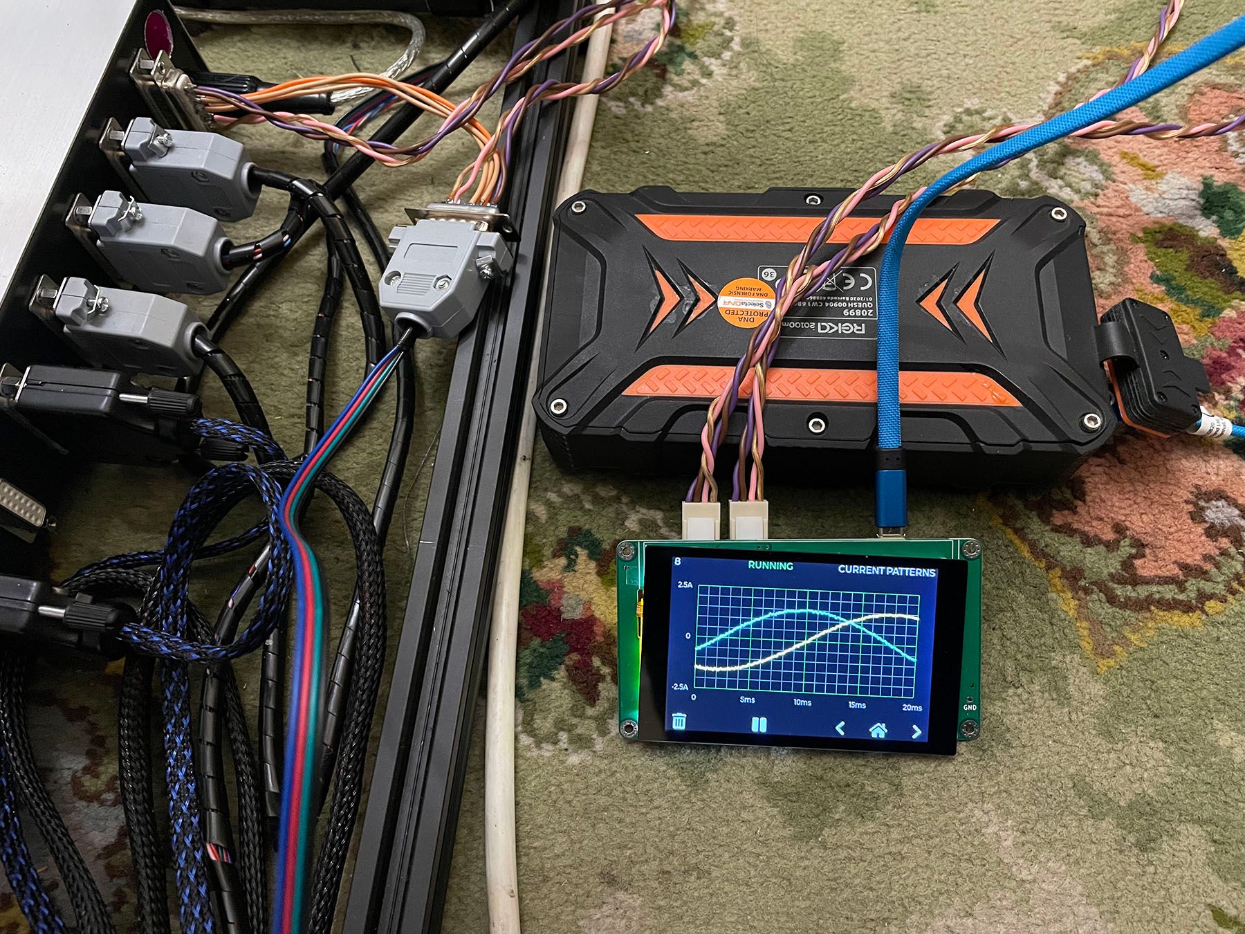
The Mouser TMCS1101A4BQDT ICs seem to work perfectly!
I've made a harness to connect in to the axis motor sockets on the control box, which is fine for those (but the extruders are run from individual toolboards).
[I have printed an enclosure, but then discovered I don't have any thin double-sided tape to attach the display... I'll get some later on].


-
@rjenkinsgb, very nice build!
A couple of notes:
- Theoretically the analyzer needs only 4 wires to measure the currents of the two coils. You can build a harness that has only 4 wires with Y splitting on both ends.
- For double sided tape for the TFT, I had good experience with this kind of thermal tapes. They hold well and designed to be isolating. https://www.amazon.com/gp/product/B072JJD2ND . I also use them between the Pico and the PCB for extra isolation.
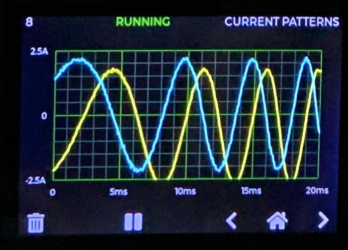
- You mention residual current (0.04A in the picture). I presume that you set the zero in the Settings screen.
-
A question for the people that uses various current sensors, how do tell the firmware what is the mv/A sensitivity of the sensor you use?
I don't think that this kind of equipment needs to be supper accurate in the current measurement but it's nice to keep it reasonably close, e.g. +/-5%.
-
@th0mpy
Thank you for your explanation.
I have now found a couple of TMCS1101A4BQDT that I wanted to order.It doesn't really matter what kind of stepper I analyze. I wanted to install the analyzer on my NEMA23 as a permanent display
-
@zapta said in Anybody wants a stepper motor analyzer?:
A couple of notes:
- Theoretically the analyzer needs only 4 wires to measure the currents of the two coils. You can build a harness that has only 4 wires with Y splitting on both ends.
- For double sided tape for the TFT, I had good experience with this kind of thermal tapes. They hold well and designed to be isolating. https://www.amazon.com/gp/product/B072JJD2ND . I also use them between the Pico and the PCB for extra isolation.
- You mention residual current (0.04A in the picture). I presume that you set the zero in the Settings screen.
I realise only two through connections are monitored, but the harness needs two connectors at either end anyway..
To fix the display, I put a few strips of kapton on the back & over the rear of the motor connectors to ensure good insulation, then some generic thin double sided tape to hold things together.
Yes, it has been zero'd - the readings fluctuate randomly +/- a small amount with no connections. When I first turned the unit on, it read somewhere around 300 - 400mA on each channel.
It's a really nice design, the options and screen responsiveness are great. Playing around with it, I realised it can do for something else I have been intending to make for some time - an encoder tester for machine tool systems.
If I add a pair of analog differential inputs with selectable gain in place of the current sensors on one, it can monitor either sine or digital encoders & linear scale signals - pretty much just change the Amps indication for Volts!
-
@zapta said in Anybody wants a stepper motor analyzer?:
A question for the people that uses various current sensors, how do tell the firmware what is the mv/A sensitivity of the sensor you use?
If you get some TMCS1101A4BQDT ICs, they are the same sensitivity as the original ones.
-
@rjenkinsgb said in Anybody wants a stepper motor analyzer?:
TMCS1101A4BQDT
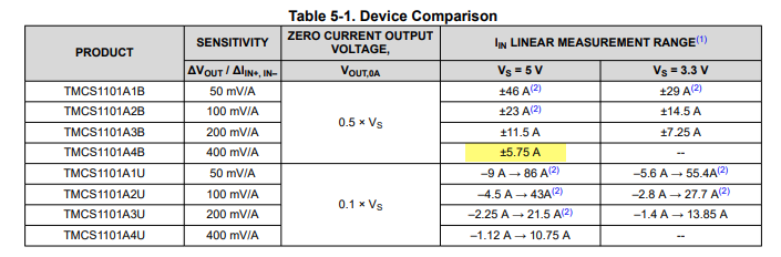
The datasheet of the TMCS1101A4BQDT suggests that it requires 5V supply. Does it work well with 3.3V?
-
@zapta It seems that either 3.3v or 5v work just fine. The limits are just a little different.
-
@th0mpy said in Anybody wants a stepper motor analyzer?:
@zapta It seems that either 3.3v or 5v work just fine. The limits are just a little different.
Good to know. Thanks. Yes, 3.3 will cause saturation for +/-5.75A @400mv/A but we don't need that full range, and it is specified for 3.3V for the other ranges.
-
So that the prototype housing of the AWD Stepper Motor Analyzer fits quite well, just adjust a few small things.


-
@dogma2k said in Anybody wants a stepper motor analyzer?:
AWD Stepper Motor Analyze
Wow! That's a nice design.
-
Hey everyone, I have a new batch of sensors being delivered early next week. If you're interested hit me up via chat.
-
The final case is finally ready. I also installed a FlowMeter. Everything fits in and the lid even closes.
If you like, you can download the STEP file

-
@dogma2k , looks very impressive. If you can, please post here a picture with all screen on, it will be even more cool.
")
-
@zapta
Unfortunately only provisionally because I don't have my 5V transformer an Arduino Uno yet

-
@zapta
Can the analyzer be switched on and off during operation? Because you can / should only disconnect the motors without electrical voltage. Or does it matter here because the input and output always have continuity and the measurements are only picked up in parallel? -
@dogma2k, the electronics and the stepper circuit are isolated from each other so it's safe to turn 5V power on/off even when the printer is working. It will not damage the electronic and the print will continue with no interruption.
-
The analyzer is finally running after I had to remove the display again because the soldering points of the connector had pushed through the metal frame of the display and always caused a short circuit

Thanks for the nice toy
-
@dogma2k said in Anybody wants a stepper motor analyzer?:
the soldering points of the connector had pushed through the metal frame of the display and always caused a short circuit
Wow! Looks awesome. I am glad that this didn't cause a permanent damage. I maintain the insulation by
-
Using an insulated 10mm width double tape on the back of the PCB, at the marked areas. E.g. https://www.amazon.com/Adhesive-10mmx25mx0-25mm-Thermally-Conductive-Computer/dp/B075FRPXQ5 . I also apply it between the PCB and the PICO, just in case.
-
Pre cutting the servo connectors pins such that they don't protrude at the back of the connector. This is the trimming jig I use https://github.com/zapta/simple_stepper_motor_analyzer/blob/main/3d/connector_trim_jig.stl
BTW, it should be ok to connect multiple analyzers to the same servo since the sensors serial resistance is very low.
-
-
@dogma2k, the current readings seem have have offset. You may want to reset it in the Settings screen with the motor disconnected (that is, zero current).