Duet3D Logo Duet3D
    • Tags
    • Documentation
    • Order
    • Register
    • Login

    Anybody wants a stepper motor analyzer?

    Scheduled Pinned Locked Moved
    General Discussion
    56
    281
    31.6k
    Loading More Posts
    • Oldest to Newest
    • Newest to Oldest
    • Most Votes
    Reply
    • Reply as topic
    Log in to reply
    This topic has been deleted. Only users with topic management privileges can see it.
    • rjenkinsgbundefined
      rjenkinsgb @zapta
      last edited by

      @zapta said in Anybody wants a stepper motor analyzer?:

      A question for the people that uses various current sensors, how do tell the firmware what is the mv/A sensitivity of the sensor you use?

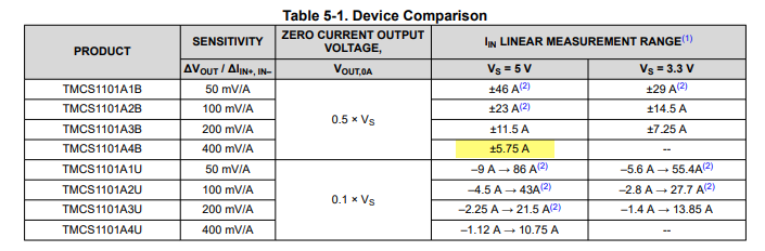
      If you get some TMCS1101A4BQDT ICs, they are the same sensitivity as the original ones.

      Robert J.

      Printers: Overlord pro, Kossel XL+ with Duet 6HC and "Frankentron", TronXY X5SA Pro converted to E3D toolchange with Duet 6HC and 1LC toolboards.

      zaptaundefined 1 Reply Last reply Reply Quote 0
      • zaptaundefined
        zapta @rjenkinsgb
        last edited by

        @rjenkinsgb said in Anybody wants a stepper motor analyzer?:

        TMCS1101A4BQDT

        The datasheet of the TMCS1101A4BQDT suggests that it requires 5V supply. Does it work well with 3.3V?

        524a2d7f-b32a-4c0b-a748-b8b01e234573-2021-11-25_21-03-52.png

        Th0mpyundefined 1 Reply Last reply Reply Quote 0
        • Th0mpyundefined
          Th0mpy @zapta
          last edited by

          @zapta It seems that either 3.3v or 5v work just fine. The limits are just a little different.

          Usually the team that scores the most points wins the game.

          zaptaundefined 1 Reply Last reply Reply Quote 0
          • zaptaundefined
            zapta @Th0mpy
            last edited by zapta

            @th0mpy said in Anybody wants a stepper motor analyzer?:

            @zapta It seems that either 3.3v or 5v work just fine. The limits are just a little different.

            Good to know. Thanks. Yes, 3.3 will cause saturation for +/-5.75A @400mv/A but we don't need that full range, and it is specified for 3.3V for the other ranges.

            1 Reply Last reply Reply Quote 0
            • Dogma2kundefined
              Dogma2k
              last edited by

              So that the prototype housing of the AWD Stepper Motor Analyzer fits quite well, just adjust a few small things.

              Front.jpg
              Back.jpg

              zaptaundefined 1 Reply Last reply Reply Quote 1
              • zaptaundefined
                zapta @Dogma2k
                last edited by

                @dogma2k said in Anybody wants a stepper motor analyzer?:

                AWD Stepper Motor Analyze

                Wow! That's a nice design.

                1 Reply Last reply Reply Quote 0
                • Th0mpyundefined
                  Th0mpy
                  last edited by

                  Hey everyone, I have a new batch of sensors being delivered early next week. If you're interested hit me up via chat.

                  Usually the team that scores the most points wins the game.

                  1 Reply Last reply Reply Quote 0
                  • Dogma2kundefined
                    Dogma2k
                    last edited by Dogma2k

                    The final case is finally ready. I also installed a FlowMeter. Everything fits in and the lid even closes.
                    If you like, you can download the STEP file

                    https://a360.co/3sl2Kge

                    Back_neu.jpg
                    Front_neu.jpg

                    zaptaundefined 1 Reply Last reply Reply Quote 1
                    • zaptaundefined
                      zapta @Dogma2k
                      last edited by

                      @dogma2k , looks very impressive. If you can, please post here a picture with all screen on, it will be even more cool. 😉

                      Dogma2kundefined 1 Reply Last reply Reply Quote 0
                      • Dogma2kundefined
                        Dogma2k @zapta
                        last edited by

                        @zapta
                        Unfortunately only provisionally because I don't have my 5V transformer an Arduino Uno yet
                        Front_neu_on.jpg

                        1 Reply Last reply Reply Quote 1
                        • Dogma2kundefined
                          Dogma2k
                          last edited by

                          @zapta
                          Can the analyzer be switched on and off during operation? Because you can / should only disconnect the motors without electrical voltage. Or does it matter here because the input and output always have continuity and the measurements are only picked up in parallel?

                          zaptaundefined 1 Reply Last reply Reply Quote 0
                          • zaptaundefined
                            zapta @Dogma2k
                            last edited by

                            @dogma2k, the electronics and the stepper circuit are isolated from each other so it's safe to turn 5V power on/off even when the printer is working. It will not damage the electronic and the print will continue with no interruption.

                            1 Reply Last reply Reply Quote 0
                            • Dogma2kundefined
                              Dogma2k
                              last edited by

                              The analyzer is finally running after I had to remove the display again because the soldering points of the connector had pushed through the metal frame of the display and always caused a short circuit
                              IMG_4717.jpg

                              Thanks for the nice toy 😉

                              zaptaundefined 2 Replies Last reply Reply Quote 0
                              • zaptaundefined
                                zapta @Dogma2k
                                last edited by zapta

                                @dogma2k said in Anybody wants a stepper motor analyzer?:

                                the soldering points of the connector had pushed through the metal frame of the display and always caused a short circuit

                                Wow! Looks awesome. I am glad that this didn't cause a permanent damage. I maintain the insulation by

                                1. Using an insulated 10mm width double tape on the back of the PCB, at the marked areas. E.g. https://www.amazon.com/Adhesive-10mmx25mx0-25mm-Thermally-Conductive-Computer/dp/B075FRPXQ5 . I also apply it between the PCB and the PICO, just in case.

                                2. Pre cutting the servo connectors pins such that they don't protrude at the back of the connector. This is the trimming jig I use https://github.com/zapta/simple_stepper_motor_analyzer/blob/main/3d/connector_trim_jig.stl

                                BTW, it should be ok to connect multiple analyzers to the same servo since the sensors serial resistance is very low.

                                Dogma2kundefined 1 Reply Last reply Reply Quote 0
                                • zaptaundefined
                                  zapta @Dogma2k
                                  last edited by

                                  @dogma2k, the current readings seem have have offset. You may want to reset it in the Settings screen with the motor disconnected (that is, zero current).

                                  edbe7e83-1f85-48ed-84c7-21956287a033-2021-12-29_10-24-43.png

                                  1 Reply Last reply Reply Quote 0
                                  • Dogma2kundefined
                                    Dogma2k @zapta
                                    last edited by Dogma2k

                                    @zapta said in Anybody wants a stepper motor analyzer?:

                                    1. Using an insulated 10mm width double tape on the back of the PCB, at the marked areas. E.g. https://www.amazon.com/Adhesive-10mmx25mx0-25mm-Thermally-Conductive-Computer/dp/B075FRPXQ5 . I also apply it between the PCB and the PICO, just in case.

                                    I had double-sided tape in between. Wasn't enough
                                    https://www.amazon.de/gp/product/B08YJK6L1T/ref=ppx_yo_dt_b_asin_title_o07_s00?ie=UTF8&psc=1
                                    It didn't matter, it went well, it was just fun to find the fault ...

                                    1. Pre cutting the servo connectors pins such that they don't protrude at the back of the connector. This is the trimming jig I use https://github.com/zapta/simple_stepper_motor_analyzer/blob/main/3d/connector_trim_jig.stl

                                    That would probably have been the best had I done that

                                    BTW, it should be ok to connect multiple analyzers to the same servo since the sensors serial resistance is very low.

                                    Even more? I already need 4 pieces because I have 2x X steppers and 2x Y steppers.
                                    The small OLED is also not yet in operation for the filament flow meter, because I haven't had time to get the Arduino UNO ready

                                    I still have a problem that as soon as the motors are working, the display does not react at all or almost not at all.
                                    If the motors are switched off with M84 then you can use the display properly.
                                    How come that

                                    Analyzer_standby.mp4
                                    Analyzer_aktion.mp4

                                    zaptaundefined 1 Reply Last reply Reply Quote 0
                                    • zaptaundefined
                                      zapta @Dogma2k
                                      last edited by

                                      @dogma2k said in Anybody wants a stepper motor analyzer?:

                                      I still have a problem that as soon as the motors are working, the display does not react at all or almost not at all

                                      Can you explain what what you mean? Chan you change pages? Do you see any reading on the main page?

                                      Per my previous post, it seems that your sensors need zero calibration. This is done in the Settings page (accessible from the main page) with the motor disconnected.

                                      Dogma2kundefined 1 Reply Last reply Reply Quote 0
                                      • Dogma2kundefined
                                        Dogma2k @zapta
                                        last edited by

                                        @zapta said in Anybody wants a stepper motor analyzer?:

                                        @dogma2k said in Anybody wants a stepper motor analyzer?:

                                        I still have a problem that as soon as the motors are working, the display does not react at all or almost not at all

                                        Can you explain what what you mean? Chan you change pages?

                                        Would you have to recognize property in the two videos what I mean (if not, I'll make better ones)
                                        If no stepper has been used, I can switch through the menus, as soon as the stepper has moved once, the displays can no longer be operated.

                                        I'll do the zeroing with disconnected stepper afterwards when I'm back.

                                        Th0mpyundefined 1 Reply Last reply Reply Quote 0
                                        • Th0mpyundefined
                                          Th0mpy @Dogma2k
                                          last edited by

                                          @dogma2k I had this issue on my first analyzer I boiled it down to a couple things.

                                          As @zapta mentions, if you don't cut the pins there may just enough bite into the back of the LCD which shorts things out. I pulled the connectors out, recut, and used some 3M VHB to secure the LCDs.

                                          Finally, double check the castellated pins on the PICO and make sure they're solid. If you used a thicker adhesive behind the PICO it might prevent good connections.

                                          Usually the team that scores the most points wins the game.

                                          Dogma2kundefined 1 Reply Last reply Reply Quote 0
                                          • Dogma2kundefined
                                            Dogma2k @Th0mpy
                                            last edited by

                                            @th0mpy said in Anybody wants a stepper motor analyzer?:

                                            @dogma2k I had this issue on my first analyzer I boiled it down to a couple things.

                                            How can you reduce the choice, I really don't have a clue about it yet.
                                            I took the APPLICATION.uf2 file from the temp directory on github, was it wrong?

                                            Finally, double check the castellated pins on the PICO and make sure they're solid. If you used a thicker adhesive behind the PICO it might prevent good connections.

                                            Now the analyzers just don't run properly when the steppers are moving.
                                            So it is more as if the Pico does not have enough power to process the incoming data quickly enough

                                            zaptaundefined 1 Reply Last reply Reply Quote 0
                                            • First post
                                              Last post
                                            Unless otherwise noted, all forum content is licensed under CC-BY-SA