Smart Effector issue
-
Your dive speed seems to be half the recommended value. M558 F600 vs M558 F1200
https://docs.duet3d.com/en/Duet3D_hardware/Accessories/Smart_Effector#configuring-firmware
M558 P8 R0.8 C"probe+servo0" H10 F600 T2000
M558 P8 R0.4 F1200
So perhaps it's not striking with enough force to reliably trigger.
-
And looks like that, had to go all way up to 2500 to get reliable trig.
Where do I set hotend offset and where to set effector offset?
Looking from front X0/Y0 effector is to left and the hotend is a bit left too. -
@tecno said in Smart Effector issue:
Where do I set hotend offset and where to set effector offset?
Looking from front X0/Y0 effector is to left and the hotend is a bit left too.I'm not sure what you mean.
-
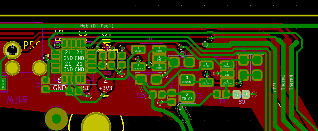
FWIW we've identified a modification to the Smart Effector version 3 that improves the signal-to-noise ratio, which in turn allows you to use a higher sensitivity unless fan noise etc. prevents that. The modification is to remove capacitor C8. This can be done using a soldering iron with a bit large enough to cover both pads. Alternatively, you could use a small twist drill bit to remove a thin sliver of copper around the adjacent via that connects one end of the capacitor to the ground plane.

This image is as viewed from the top of the PCB, so you need to invert it when looking at the bottom.
-
@phaedrux said in Smart Effector issue:
@tecno said in Smart Effector issue:
Where do I set hotend offset and where to set effector offset?
Looking from front X0/Y0 effector is to left and the hotend is a bit left too.I'm not sure what you mean.
; Tools
M563 P0 D0 H1 F0 ; define tool 0
G10 P0 X-4 Y0 Z0 ; set tool 0 axis offsets
G10 P0 R0 S0Fixed offset issue
-
@dc42 said in Smart Effector issue:
FWIW we've identified a modification to the Smart Effector version 3 that improves the signal-to-noise ratio, which in turn allows you to use a higher sensitivity unless fan noise etc. prevents that. The modification is to remove capacitor C8. This can be done using a soldering iron with a bit large enough to cover both pads. Alternatively, you could use a small twist drill bit to remove a thin sliver of copper around the adjacent via that connects one end of the capacitor to the ground plane.

This image is as viewed from the top of the PCB, so you need to invert it when looking at the bottom.
So far during my tests no fans are used, good to know when adding fans.
-
Still some issues with false trig = does not go down but LED lights up = trig.
How to solve this?
-
When and where was it purchased?
-
Warning: Skipping grid point X=40.0, Y=60.0 because Z probe cannot reach it
37 points probed, min error -0.260, max error 0.240, mean -0.026, deviation 0.113
Height map saved to file 0:/sys/heightmap.csvFrom where does this X=40.0, Y=60.0 coordinate originate?
-
-
@tecno said in Smart Effector issue:
And looks like that, had to go all way up to 2500 to get reliable trig.
Where do I set hotend offset and where to set effector offset?
Looking from front X0/Y0 effector is to left and the hotend is a bit left too.Now on 3500 and the false trigs seems to be away, but need more testing to be sure.
Also Dive height affects this now on 5mm -
@tecno have you tried the following to eliminate the false triggering:
- increase the R parameter in the M558 command, in case it is the previous XY move causing the spurious triggering;
- reduce the probing acceleration, because it may be the Z acceleration at the start of the probing move that causes the spurious triggering.
-
@dc42 said in Smart Effector issue:
@tecno have you tried the following to eliminate the false triggering:
- increase the R parameter in the M558 command, in case it is the previous XY move causing the spurious triggering;
- reduce the probing acceleration, because it may be the Z acceleration at the start of the probing move that causes the spurious triggering.
Tried R0.8 still the issue +++ Will not go down to bed on all points !!!
-
@tecno said in Smart Effector issue:
From where does this X=40.0, Y=60.0 coordinate originate?
Assuming you're doing a G29 there, the grid spacing is determined by M557 in your config.g
https://docs.duet3d.com/en/User_manual/Connecting_hardware/Z_probe_mesh_bed
-
@phaedrux said in Smart Effector issue:
@tecno said in Smart Effector issue:
From where does this X=40.0, Y=60.0 coordinate originate?
Assuming you're doing a G29 there, the grid spacing is determined by M557 in your config.g
https://docs.duet3d.com/en/User_manual/Connecting_hardware/Z_probe_mesh_bed
Thanks, now it gets a bit clearer.
-
after watching our vid our prob are the short rods...but makeing the effector mount wider just makes it softer..more bending while probing. Other problen, that i had on my Delta with faulty sensivity..heatbreak came loose...so it looses lots of sensivity.
About your Rods...when i designed my delta some years ago there where plently of sites to calculate things like Rod lenght...max angles of rods. Maybe DC42 still have some links to such a calculator. It would be much better to have longer rods..if its ok to loose some build height. Your construction is prone to effector tilts that affects the stability while probing -
@barracuda72 said in Smart Effector issue:
after watching our vid our prob are the short rods...but makeing the effector mount wider just makes it softer..more bending while probing. Other problen, that i had on my Delta with faulty sensivity..heatbreak came loose...so it looses lots of sensivity.
About your Rods...when i designed my delta some years ago there where plently of sites to calculate things like Rod lenght...max angles of rods. Maybe DC42 still have some links to such a calculator. It would be much better to have longer rods..if its ok to loose some build height. Your construction is prone to effector tilts that affects the stability while probingThe rods and the adapter are original Dreammaker OverLord PRO, going back to a larger/wider effector (original adapter) made the situation better. Only trying to get this old Delta printer functional with a bit more modern parts.
I am in a process of building a large Delta of 1.4m height and ~550mm print diameter, Rods 610mm long directly to Smart Effector via magnets. -
Can somebody show me how mesh.g is written? To be run with G29
-
@tecno This is what I use.
; mesh.g
; called to load/make heightmap.csv
M98 P"/macros/ResetBabystepping"
M561       ; clear any bed transform
while iterations < #move.axes & move.axes[iterations].visible
  if !move.axes[iterations].homed
     G28
     break
G29 S1        ; load heightmap.csv
if result > 1 ; make if it doesn't exist
	G29 S0
That {1} isn't in it.
-
@stephen6309 said in Smart Effector issue:
@tecno This is what I use.
; mesh.g
; called to load/make heightmap.csv
M98 P"/macros/ResetBabystepping"
M561       ; clear any bed transform
while iterations < #move.axes & move.axes[iterations].visible
  if !move.axes[iterations].homed
     G28
     break
G29 S1        ; load heightmap.csv
if result > 1 ; make if it doesn't exist
	G29 S0
That {1} isn't in it.
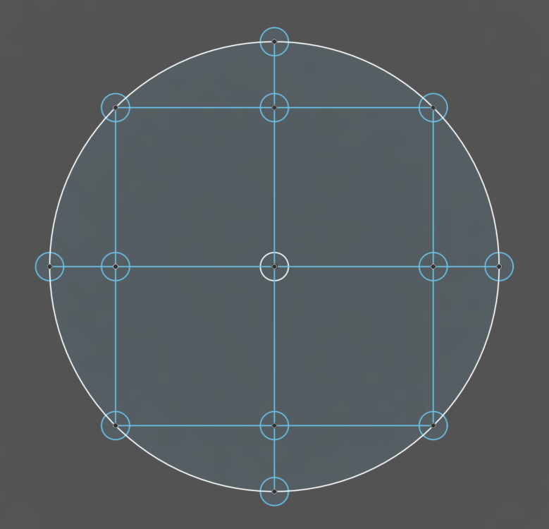
Not what I was looking for, below a mesh of small circles I want to probe But do not how to write that mesh.g file.
