New heated enclosure printer
-
@coseng That duct looks pretty restrictive for an axial fan.
-
@phaedrux Well rev1 did not fit because I did the bellows mounting on the fly and was not in the CAD model! So I'll make rev2 bigger.
-
Do you have a radial blower fan for more static pressure?
-
@phaedrux I was thinking it would not need significant amounts of air, but I good point, why underestimate? Let me see what I have in the back with some more oomph.
-
@sebkritikel said in New heated enclosure printer:
Could you upload the gcode for this print? Would like to take a peek and see whats going on there.
https://drive.google.com/file/d/1bjFQm2guAu9zjHL3NyoJ2kZlp8FMA5ES/view?usp=sharing
Here it is zipped.
-
@coseng Thank you!
I was trying to see if any of Cura's coasting settings were configured, but nope, the gcode looks pretty good. You're printing ABS right? In the specific image I quoted, I think a small amount of part cooling could be beneficial - taking into account the slight overhang you're printing combined with the corner segments and movement speed. I'd guess the material is peeling back during those segments.
I've found ABS doesn't need as extreme of cooling as PLA does at similar feed rates. Really, ABS does quite well without cooling, but a small amount has helped me solidify my overhangs+corner sections.
Your general surface finish is much improved - I try to print my inner walls first, followed by my outer walls, and then my infill segments- helps me avoid any infill bleed-through (I do allow for some infill overlap with my inner walls in Cura).
For pressure advance, there are a few good calibration macros (that allow you to set your PA range, line segment lengths+speeds), but I find the best values there are a hair conservative. Try printing the Klipper ringing tower (maybe a few bottom layers, but otherwise inner and outer walls only - no infill or top surface layers), sweeping across PA values (starting with 0, ending with a fairly high value). A good area to look at is this section:
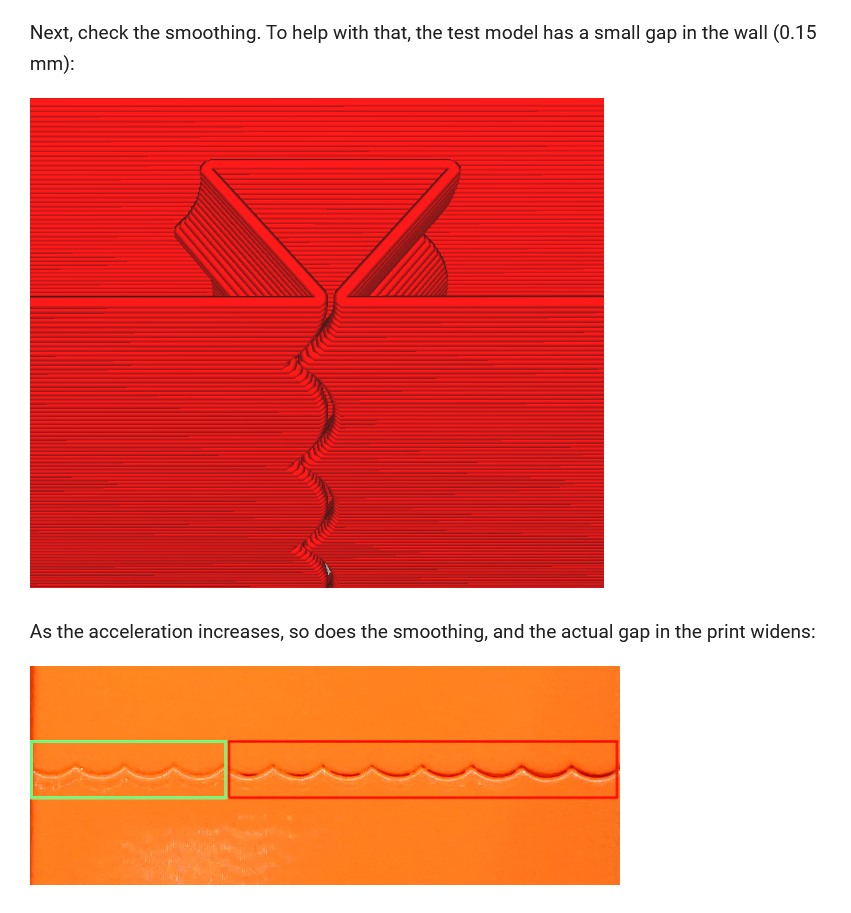
While that doc is detailing input shaping, you'll see (and feel) the PA impacts on the areas indicated by green and red. -
@sebkritikel OK, thanks for the info. This part just ran overnight, 5hr35min, and I think came out quite good. It is definitely better than the thin wall version and not much heavier and a lot stiffer. The problem is this technique is not applicable to all of the parts. I will do it when possible, but will dedicate today to running some of these calibration processes in the hope of getting both types of parts running well.


Instead of the ribs of the previous runs, this is modeled as solid with some cutouts for the mounting holes.


There are a few printing artifacts and hopefully today's activities will help to address them, but I'm very happy with these very usable parts.
-
Made and ran a PA test part with geometry similar to my problem areas. This part's toolpaths are one continuous pass per layer, no infill, retractions, etc. 0.8mm nozzle, 0.5mm layer height. 135mm/sec actual print speed.

It printed mostly great, with the exception of one area:

The location of this problem points strongly to thermal issues of the extrusion bead cooling, so next on deck is the layer fan.
The PA test changes were subtle and easier felt with your fingertips and not a camera. Best value seems to be 0.03 where there was the least amount of bulging at the rib ends but no other weirdness at corners and transitions.

Progress!
-
@dc42 I'm having a little trouble in paradise this evening. I was about to install the layer fan and had modified the system.cfg file to add the two lines for fan definition, and noticed the DWC with the wired internet connection was acting sluggishly. I made an error with the config.sys file in not changing the numbers from 3 to 4 to add the fan. I updated the file by changing those two lines, and I clicked reboot mainboard for the updated config.sys file and presto, the web browser could not reconnect with the printer.
I did the 'ol printer reboot, and then the paneldue partially booted but had 'connecting' in the upper right corner and the bed temps and other displays were not present and I still had no ethernet connectivity. I did another reboot and the paneldue now did not display anything, just blank with the backlight on.
Windows says that nothing is plugged in to the internet port and none of the ethernet plug lights are on on either end.
Before I started messing around and doing something stupid, I was hoping for a little guidance.
-
@coseng said in New heated enclosure printer:
Before I started messing around and doing something stupid, I was hoping for a little guidance.
Take a look through this guide and see how far you can get.
https://docs.duet3d.com/en/User_manual/Troubleshooting/Duet_wont_respond
-
@phaedrux Thanks. I see a USB port in devmgr but it is listed as 'USB Serial Device (COM3)' , not any of the options listed in the guide.
-
Are you able to reach it through a USB serial terminal like YAT?
-
@phaedrux YAT says access to COM3 is denied. The last time I used YAT was to set the 6HC up so the setting should be the same.
-
What LEDs are lit when power is applied, either through VIN or USB?
-
@phaedrux The proper LEDs from the recover guide are lit. I reinstalled the windows drivers and now have 'Duet3 Motion control Electronics (COM3)' listed in devmgr and can connect in YAT. A M115 gives me this response:
'FIRMWARE_NAME: RepRapFirmware for Duet 3 MB6HC FIRMWARE_VERSION: 3.4.0 ELECTRONICS: Duet 3 MB6HC v1.01 or later FIRMWARE_DATE: 2022-03-15 18:57:26
ok' -
@phaedrux OK, I was able to use the 'fallback procedure #1' from the recovery guide, copied the 3.4.1 files to the sd card, performed the update with yat, then did a M115 and received the confirmation with the updated firmware version. Still get nothing from the ethernet connection and DWC. No lights on the ethernet port and Windows says the cable is unplugged. Paneldue is still blank. One slow blinking LED between SD card and reset switch, then the group of 4 leds, green, red, orange, blue, are all solid lit.
-
Are the files on the SD card still intact?
It almost sounds like it's not reading the SD card, or config.g files.
Can you try sending some commands over YAT to see if you can bring up networking and the paneldue?
M552 S1 (or whatever you're using for networking)
M575 P1 B57600 S1 for the paneldue.
-
@phaedrux SD card is readable but the config.sys was empty. I copied the .old file to overwrite it. Reinserted the SD card, now have green LEDs on the network port but still can't connect to dwc. Am using fixed IP of 168.192.2.1 and confirmed using yat and a M552. I can ping it from a command prompt and get replies. Paneldue is still blank, even if i send a M575 P1 B57600 S1 and get an ok confirmation.
Chris
Cosentino Engineering -
@phaedrux OK, go tthe network working and can connecto via DWC and the fan modifications to the config.g are still there so hopefully the rest of the configuration is correct.
The paneldue is still blank. Config.g is:
; Configuration file for Duet 3 (firmware version 3.3)
; executed by the firmware on start-up
;
; generated by RepRapFirmware Configuration Tool v3.3.10 on Thu Apr 14 2022 23:29:28 GMT-0400 (Eastern Daylight Time); General preferences
M575 P1 S1 B57600 ; enable support for PanelDue
G90 ; send absolute coordinates...
M83 ; ...but relative extruder moves
M550 P"hyperprinter" ; set printer name
M669 K1 ; select CoreXY mode
M564 H0 ; allow moves before homing; Wait a moment for the CAN expansion boards to start
G4 S2; Network
M552 P192.168.2.1 S1 ; enable network and set IP address
M553 P255.255.255.0 ; set netmask
M554 P192.168.2.20 ; set gateway
M586 P0 S1 ; enable HTTP
M586 P1 S0 ; disable FTP
M586 P2 S0 ; disable Telnet; Drives
M569 P0.1 S0 ; physical drive 0.1 goes forwards
M569 P0.2 S0 ; physical drive 0.2 goes forwards
M569 P0.0 S1 ; physical drive 0.0 goes forwards
M569 P121.0 S1 ; physical drive 121.0 goes forwards
M584 X0.1 Y0.2 Z0.0 E121.0 ; set drive mapping
M350 X128 Y128 Z8 E16 I1 ; configure microstepping with interpolation
M92 X56.14 Y56.14 Z320.00 E837.00 ; set steps per mm
M566 X500.00 Y500.00 Z60.00 E120.00 ; set maximum instantaneous speed changes (mm/min)
M203 X50000.00 Y50000.00 Z1000.00 E1200.00 ; set maximum speeds (mm/min)
M201 X10000.00 Y10000.00 Z50.00 E3000.00 ; set accelerations (mm/s^2)
M906 X300 Y300 Z5900 E1500 I30 ; set motor currents (mA) and motor idle factor in per cent
M84 S20 ; Set idle timeout
M572 D0 S0.03; CLEARPATH STEPPER TIMING
M569 P1 R1 T2
M569 P2 R1 T2; Axis Limits
M208 X-300 Y-250 Z0 S1 ; set axis minima
M208 X300 Y250 Z950 S0 ; set axis maxima; Endstops
M574 X2 S1 P"121.io2.in" ; configure switch-type (e.g. microswitch) endstop for low end on X via pin 121.io2.in
M574 Y1 S1 P"io1.in" ; configure switch-type (e.g. microswitch) endstop for low end on Y via pin io1.in
M574 Z1 S2 ; configure Z-probe endstop for low end on Z; Z-Probe
M950 S0 C"121.io0.out" ; create servo pin 0 for BLTouch
M558 P9 C"121.io0.in" H5 F120 A1 T20000 ; set Z probe type to bltouch and the dive height + speeds
G31 P500 X-2.31 Y-13.53 Z2.91 ; set Z probe trigger value, offset and trigger height
M557 X-290:290 Y-240:224 S116 ; define mesh grid; Heaters
M308 S0 P"temp0" Y"pt1000" ; configure sensor 0 as PT1000 on pin temp0
M950 H0 C"out0" T0 ; create bed heater output on out0 and map it to sensor 0
; M307 H0 R0.379 K0.064:0.000 D4.11 E1.35 S1.00 B0 OLD FROM FIRST TUNING RUN
M307 H0 R0.158 K0.054:0.000 D37.27 E1.35 S1.00 B0 ; FROM SECOND TUNING RUN WITH BED MOUNTED SENSOR
M140 H0 ; map heated bed to heater 0
M143 H0 S120 ; set temperature limit for heater 0 to 120C
M308 S1 P"temp1" Y"thermistor" T1000 ; configure sensor 3 as two 500 ohm thermistors in series on pin temp1
M950 H1 C"out1" T1 ; create chamber heater output on out1 and map it to sensor 1
M307 H1 R0.292 K0.731:0.000 D3.86 E1.35 S1.00 B0 ; FROM FIRST TUNING RUN
M141 H1 ; map chamber to heater 1
M143 H1 S150 ; set temperature limit for heater 1 to 150C
M308 S2 P"121.temp0" Y"pt1000" ; configure sensor 2 as PT1000 on pin 121.temp0
M950 H2 C"121.out0" T2 ; create nozzle heater output on 121.out0 and map it to sensor 2
M307 H2 R1.544 K0.166:0.000 D6.33 E1.35 S1.00 B0 V23.1 ; FROM FIRST TUNING RUN
M143 H2 S320 ; set temperature limit for heater 2 to 320C; Fans
M950 F0 C"out4" Q500 ; create fan 0 on pin out4 and set its frequency
M106 P0 C"Chamber 1" S1 H-1 ; set fan 0 name and value. Thermostatic control is turned off
M950 F1 C"out5" Q500 ; create fan 1 on pin out5 and set its frequency
M106 P1 C"Chamber 2" S1 H-1 ; set fan 1 name and value. Thermostatic control is turned off
M950 F2 C"121.out2" Q500 ; create fan 2 on pin 121.out2 and set its frequency
M106 P2 C"XY Extruder" S1 H-1 ; set fan 2 name and value. Thermostatic control is turned off
M950 F3 C"out7" Q500 ; create fan 3 on pin out7 and set its frequency
M106 P3 C"Water Cooler" S1 H-1 ; set fan 3 name and value. Thermostatic control is turned offM950 F4 C"121.out1" Q500 ; create fan 4 on pin 121.out1 and set its frequency
M106 P4 C"Layer fan" S1 H-1 ; set fan 4 name and value. Thermostatic control is turned off; Tools
M563 P0 S"xyhead" D0 H2 F2 ; define tool 0
G10 P0 X0 Y0 Z0 ; set tool 0 axis offsets
G10 P0 R0 S0 ; set initial tool 0 active and standby temperatures to 0C; Custom settings
M950 D1 C"spi.cs0+spi.cs2" -
@Phaedrux Even though the paneldue is blank I can access the files on the sd card.